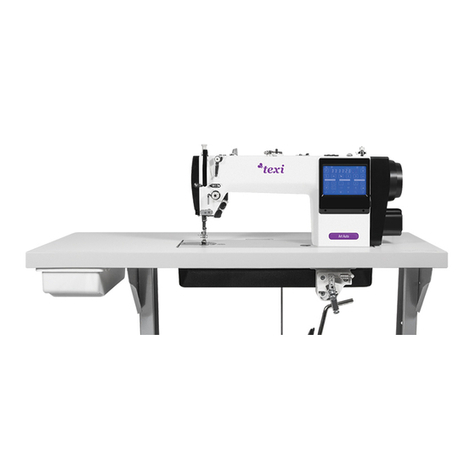
Texi Tronic 1 NEO User manual

Operation manual
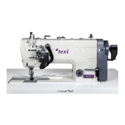
lockstitch machine
for high speed direct drive
with built-in energy saving motor
Tronic 1 NEO

TEXI Tronic 1 NEO - Operation manual

TEXI Tronic 1 NEO - Operation manual
CONTENTS
Safety precautions 1
User's manual 2
1. Before starting work 2
2. Mounting the machine 3
3. Lubrication of machine 3
4. Mounting the thread stand 4
5. Mounting the needle 4
6. Mounting the bobbin 4
7. Installation of bobbin case 5
8. Winding up the bobbin thread 5
9. Threading 6
10. Lifting of presser foot 7
11. Adjusting the stitch length and the use of back feeding lever 7
12. Hand-touch backstitch device 7
13. Operating the treadle 8
14. Adjusting the treadle 8
15. Oil mass adjustment of rotating hook 9
16. Adjusting the presser foot pressure 10
17. Adjusting the height and angle of presser foot 10
18. Adjustment of the knee lift height 11
19. Adjusting the tension of stitch thread 11
20. Adjusting the take-up amount of take-up lever 12
21. Adjust the height of the needle bar 12
22. Adjusting the take-up spring 13
23. Adjust the synchronization of the needle and hook 13
24. Adjust the synchronization of the needle and feed 14
25. Adjustment of the height of feed dog 15
26. Adjust the lean of feed dog 15
27. Maintenance 16
28. Carrying and placing of the sewing machine 17
Ask your supplier about 18
CE Declaration of Conformity 19

SAFETY PRECAUTION
This instruction manual contains important guidelines regarding correct, safe and economical method of use of the machine.
Following recommendations contained in this manual will decrease work down-time, increase machine reliability and durability,
and will make work safer.
This instruction manual must always be available at the workplace. The machine can be serviced only by an employee trained
in Industrial Safety, after reading this instruction manual.
The supplier is not responsible for damages caused by improper use or by usage of this product for functions other than those
it has been designed for.
To minimize the risk of fire, electric shock, or injury, observe the following precautions:
- Keep the workplace clean.
- Pay attention to the machine’s work environment; do not subject it to atmospheric conditions.
- Do not install the machine in rooms that are dusty, where aerosols are sprayed, or to which oxygen is supplied.
- Keep the workplace well lit.
- Be careful of danger of electric shock.
- Pay attention to clothing. Let-down hair or loose clothing can be caught by the machine’s mobile elements.
- Take care not to damage the power supply cable.
- When the machine is not in use, disconnect it from the power grid.
- Take care not to turn-on the machine accidentally.
- In case of even the slightest damage, always check if the damaged part requires replacement.
- Never install on the machine attachments and accessories other than those recommended by the manufacturer and supplier.
- Do not perform machine modifications independently.
- Do not leave near the machine unattended bystanders or children.
Electric installation
Check if the supply voltage in the electric socket corresponds to the data on the machine’s rating plate 1-phase voltage 230V
50Hz.
Check the correctness of electric connections in the plug and electric socket, observing electric shock safety countermeas-
ures.
Do not use extension power cords.
Apply the valid electrical and Industrial Safety norms.
ATTENTION – all work related to the electrical installation must be carried out by a qualified electrician.
Before starting work
Using machine without any of the safeguarding parts (finger guard, eye guard, etc.) is dangerous to an operator.
During work, only the items necessary for sewing should be found on the machine’s work table.
Before connecting the machine to the power grid, always release the pedal and the start button.
Do not use blunt or bent needles.
Do not touch any of the machine’s mobile elements, such as the needle, needle bar, thread tensioner or take-up, or hook,
during its operation.
Turn machine off before: replacing needle, threading, installing attachments, changing the bobbin or bobbin case.
If you notice any abnormalities in the machine’s function, turn it off immediately and inform a mechanic or your superior. After
finishing work, turn the machine off and remove the plug from the electric socket. In case of power grid failure, disconnect the
machine from the power grid.
This machine is not a toy!
We hope that you will use this machine with pleasure for a long time.
1
TEXI Tronic 1 NEO - Operation manual
USER’S MANUAL
The lockstitch machine TEXI Tronic 1 NEO is a high speed sewing machines, designed for sewing knitted materials
or other textiles.
Attention!
The machine is not to be used for other materials than those for which it has been designed.
Non-observance of this rule places the user at risk and can cause irreversible damage to the machine.
Before use, the user should become acquainted with this instruction manual, general safety precautions and mainte-
nance instructions.
1. Before starting work
1. After turning-on the machine and during its operation, do not touch the needle or put fingers into the thread
take-up guard.
2. During sewing, do not put fingers into the needle guard.
3. Turn power off before tilting the machine head or uninstalling parts.
4. Turn machine off before leaving it unattended.
5. Do not allow hair, loose clothing, fingers or any objects to be in the vicinity of the pulley during machine run.
6. Do not clean the machine with paint thinner.
Technical specifications
2
Model Tronic 1 NEO
Application Light medium materials
Power supply AC 220 - 240V, 550W
Sewing speed (max) 5000 stitches/min
Needle 135x5 with tips, appropriate to the type of sewn material
Lubricating oil Oil for lockstitch machine (recommended: SPIRIT 2)
Net weight 39 kg
Packaging dimensions 685 x 261 x 570 mm
Maximum stitch length
5.5 mm (standard), 13 mm (max)
Presser foot raising height
5 mm
TEXI Tronic 1 NEO - Operation manual
2. Mounting the machine
3
1. Fixing oil tray
1) Put the oil tray ② on the four groove corners on the sewing table.
2) Fix two arm cushion ① to the A side of oil tray ② (facing the operator). Fix the two stand bases ③ to the B
side of oil tray ② (hinge side),then fix the oil tray ②.
3) Insert machine head coupling hook ⑤ into the pin holes in the bottom plate such that it is embedded into the
coupling hook seat ④, and put the machine head onto the seating washer on four corners of the oil tray.
4) As shown in the picture, insert head support ⑥ into the machine table firmly.
2. Plug in the connecting wires on the electronic control.
① ①
③ ③
Fig.1
Fig.2 AB
Fig.3 ⑤
④
Fig.4 ④
⑤
② ①③
④
⑥
3. Lubrication of machine
1. Information on lubrication
1) Fill oil pan ① with sewing machine oil (10 while oil)up to MAX mark A.
2) When the oil level lowers below MIN mark B, refill the oil pan with the specified oil.
3) When you operate the machine after lubrication, you will see splashing oil through oil sight window ② if the
lubrication is adequate.
4) Note that the amount of the splash oil is unrelated to the amount of the lubricating oil.
Caution:
To prevent the unexpected startup of sewing machine, switch off the power supply before the operation is
conducted.
Fig.6
A
B
①
②
TEXI Tronic 1 NEO - Operation manual
4. Mounting the thread stand
1. As shown in right-hand figure, mount the thread
stand component onto the mounting hole for
thread stand on the sewing machine table.
2. Screw down retaining nut ① for lower segment
of thread stand lever to fix the thread stand.
①
Fig.7
5. Mounting the needle
1. Turn the upper wheel to allow the needle to reach its
maximum height.
2. Unscrew needle carrying screw ②, hold needle ① by
hand, and align the indentation A of needle to right
direction B.
3. Insert the needle into the bottom of needle hole in
direction of arrow till it reaches the end point.
4. Screw down the needle carrying screw ②.
5. Take care to ensure that the elongated slot C on the
needle is aligned to the left direction D.
Caution:
1. To prevent the unexpected startup of sewing machine,
switch off power supply before the operation is
conducted.
2. Needles are available in different sizes. Please select
appropriate needle as per the thickness of threads and
the sewing materials.
Fig.8
①
②A
B
C
D
6. Mounting the bobbin
1. Hold the rotating hook by hand, and fit the bobbin into
the rotating hook.
2. Thread the thread through the thread groove A in the
rotating hook, and draw out the thread in direction C.
In this way, the thread is led out of hole B through the
tension spring.
3. When bobbin thread is drawn, the bobbin shall turn
clockwise in direction of arrow.
A
B
C
Fig.9
4
TEXI Tronic 1 NEO - Operation manual

7. Installation of bobbin case
1. Turn the machine pulley to raise the needle until it is above
the needle plate.
2. Hold the bobbin case ① (with bobbin) with one hand, then
install the bobbin case into the hook.
Caution:
To prevent the unexpected startup of sewing machine, switch
off the power supply before the operation is conducted.
Fig.10
①
8. Winding the bobbin thread
1. Bobbin thread winding-up method
1) Fit bobbin ① onto spool ②.
2) Thread the right-hand thread coiling on thread stand as shown in right-hand figure, and reel the thread end
rightwards onto the bobbin for several turns.
3) Push winding lever ③ over to direction A, and run the sewing machine. Bobbin ① is rotated in direction C, and
thread is reeled onto bobbin ①. Once the reel is full, winding lever ③ is pushed toward direction B, and winding is
over.
4) Remove bobbin ①, and trim off the thread using winding trimmer ④.
Caution:
1. To reel bobbin thread onto bobbin ① when no sewing is performed, draw the needle thread out of hole in the take-up
lever, remove bobbin ① out of rotating hook.
2. Do not touch or lean anything to any running components when rolling the bottom line, in order to avoid the safety
accident.
2. Adjusting the bobbin thread winding
1) To adjust the winding capacity of bobbin thread, unscrew fixing screw ⑤, set winding lever ③ in direction A or
direction B, and fix screw ⑤ again. Direction A is intended for reduction, and direction B is intended for
increase(Caution:The amount of thread wound onto the bobbin should be a maximum of 80% of the bobbin
capacity).
2) If thread cannot be wound onto the bobbin flatly, unscrew nut ⑥, turn the winding tension disco, and adjust the
height of height of thread gripper plate ⑦.
a. The standard position is reached once the center heights of rotating hook ① and thread gripper plate ⑦ are
identical.
b. If the winding amount on the lower part is bigger, move the winding tension discoin direction D indicated in the
right-hand figure. If the winding amount on upper part is bigger, move the winding tension disco in direction E
indicated in the right-hand figure.
c. When the winding tension disco reaches its suitable position, screw down fixing screw ⑥.
3) Adjust the winding tension of bobbin thread by turning thread tension nut ⑧.
Thread the needle thread when needle bar stays in its highest position, lead out the thread end from the thread stand,
and conduct threading as per the serial numbers indicated in the figure.
Caution:
To prevent the unexpected startup of sewing machine, switch off the power supply before the operation is conducted.
5
TEXI Tronic 1 NEO - Operation manual
A
B
Fig.11
④
C
②
①
③
⑤Fig.12
⑥
⑦
⑧
⑦
⑦
D
E
9. Threading the needle thread
When threading the upper thread, turn the handwheel first to raise the thread take-up to the highest position, then draw
the thread from the wire rack according to the sequence number shown in the figure below.
Caution:
To prevent the unexpected startup of sewing machine, switch off the power supply before the operation is conducted.
Fig.13
①
②
③
④
⑤
⑥
⑦
⑧
⑨
⑩
11
①
②
③
④
⑤
⑥
⑦
⑧
11
⑩
⑨
6
TEXI Tronic 1 NEO - Operation manual
10. Lifting the presser foot
1. Lift presser foot controlled by hands
1) Shut down the machine, turn presser foot lever ① in direction A to uplift the presser foot (for about 5.5 mm).
2) When presser foot lever ① is turned in direction B, presser foot will be returned to its original position.
2. Lift presser foot controlled by knees
1) The presser foot ③ can be raised by pressing the knee lifter plate ②. (Height of presser lifting is relate to the
degree of knees pressing)
Note: Standard and maximal lifting height of presser foot are respectively about 10mm and 13mm when pressing
knees fully.
2) The lifting presser foot ③ lower as soon as losing the knee lifter plate ② released.
Fig.15
②
③
Fig.14
①
A
B
①
11. Adjusting stitch length and the use of back feeding lever
Adjusting stitch length
- Press needle gauge knob ① and rotate it according to arrows, do not release
it until the number you require aim at A direction right above machine head.
- Loose needle gauge knob ①.
Caution:
1. Scale mark digits are expressed on the knob in millimeter.
2. Press the reverse feeding wrench ② towards B direction and rotate needle
gauge knob ① when changing the scale of it from largest to smallest.
The use of back stitch lever
1. Press the reverse feeding wrench ① towards B direction.
2. Press towards B direction can realize back feeding.
3. Recover to forth feeding when release hands.
Fig.16
B①
A
12. Hand-touch backstitch device
1. Use of reinforce sewing
Press the reinforce sewing button ① one time, the sewing
machine reinforce forth with half stitch, press all the time, it
continues sewing with forth reinforce.
Caution: in addition to continue back reinforce sewing, the
reinforce sewing button can be as stop button ① during any
sewing condition.(before trimming)
2. Use of the light push-button
The illuminating lamp goes on at full brightness once the machine
is powered on. Push illuminating lamp control button ② to reduce
in sequence the brightness till turn off.
Fig.17
①
②
7
TEXI Tronic 1 NEO - Operation manual
13. Operating the treadle
The treadle has 4 operation levels:
1) The machine runs at low sewing speed when you
lightly depress the front part of the pedal. (as shown in
the picture B)
2) The machine runs at high sewing speed when you
further depress the front part of the pedal. (as shown in
the picture A)
3) Pedal back to the initial position when stop stepping on
it and the machine stop working. (needle in the upper or
down position as shown in the picture C)
4) The machine trims threads when you fully depress the
back part of the pedal. (as shown in the picture A)
5) When the auto-lifer is used, one more operating switch
is provided between the sewing machine stop switch
and thread trimming switch. The presser foot goes up
when you lightly depress the back part of the pedal
(D),and if you further depress the back part, the thread
trimmer is actuated. Fig.18
D
C
B
A
E
14. Adjusting the treadle
1. Adjusting the angle of treadle
1) Adjust the angle of treadle only by adjusting the length of treadle connecting rod: unscrew screw ①, and
adjust the length of treadle connecting rod by moving upward/downward the upper connecting rod ② and
lower connecting rod ③.
2) Screw down screw ① when adjustment is over.
2. Adjustment of the strength of pedal
The sewing machine run at a low speed when step forth on the panel slightly. If the strength is insufficient, hang the
stepping adjustment spring ④ on the panel spiral arm driving lever ⑤ in order to adjust strength. (a is the minimum
stepping strength, b, c, d increase gradually)
①
②
③
Fig.19
Fig.20 abcd
④
⑤
8
TEXI Tronic 1 NEO - Operation manual
3. Adjustment of stepping return strength
1) Loosen nut ⑥ and turn bolt ⑦ to adjust stepping
return strength : tighten bolt ⑦, the strength
increases; loosen bolt ⑦, the strength decreases.
2) Tighten nut ⑥ after adjusting stepping return strength.
4. Adjustment of panel moving distance
1) Remove nut ⑧.
2) Move connecting rod joint ⑨ from A to B, panel
moving distance is 1.3times than original one. Move
reversely the distance is 0.8 times as original one.
3) Assembly the nut ⑧ after adjusting panel moving
distance.
Caution:
1. To prevent the unexpected startup of sewing machine,
switch off the power supply before the operation is
conducted.
2. Stepping strength and stepping return strength both
change after adjusting panel movement, follow the steps
above to have adjustments again.
Fig.21 A
⑥
⑦
⑧
⑨
B
15. Oil mass adjustment of rotating hook
1. Adjustment method
1) Adjust the oil mass of rotating hook using adjusting
screw ①: Screw down (turn it to the right) adjusting
screw ① to raise the oil mass,or unscrew (turn it to
the right) the adjusting screw to lower the oil
mass. Amount repeatedly until the lubrication
amount is correct.
2) Check the lubrication amount again after the sewing
machine has been used for approximately two
hours.
2. Confirming the Oil Mass
1) Remove the thread from all points from the thread
take-up to the needle.
2) Use the lifting lever to lift the presser foot.
3) Run the machine at the normal sewing speed for
approximately 3 minute without sewing any material
(following the same start/stop pattern as when
actually sewing)
4) Place the lubrication amount check sheet ②
underneath the rotary hook ③ and hold it there.
Then run the sewing machine at the normal sewing
speed for 10 seconds. (Any type of paper can be
used as the lubrication amount check sheet ②)
5) Check the amount of oil which has spattered onto
the sheet ②.
Caution:
1. Prior to the above-mentioned operation, remove the
knockout plate and check whether there is oil in the oil
box.
2. Do not use fingers to touch the hook or other running
components of feeding mech anism when checking
the amount of oil for the hook to avoid the accident.
3. Use the following procedure to check the amount of oil
being supplied to the rotary hook when replacing the
rotary hook or when changing the sewing speed.
①
Fig.22
Special oil mass confirmation paper
70mm
25mm
Position for oil mass confirmation
Bottom plate
③
5-10mm
②
Fig.23
9
TEXI Tronic 1 NEO - Operation manual
3. Guide sample of oil mass adequacy
1) The guide sample shown in the right-hand
figure(see Fig. 24) may be finely adjusted
(increased or reduced) as per different sewing
processes; however, excessive increase or
reduction shall be avoided. Too little oil mass may
lead to rotating hook heating, and over
much oil mass may lead to contamination of the
sewing materials.
2) Test the oil mass 3 times using special oil mass
confirmation paper till the oil traces indicated by
the special paper show no changes.
Fig.24
Too much Too littleCorrect
Spattered oil
16. Adjusting presser foot pressure
1. Unscrew pressure adjusting nut ②.
2. Presser foot pressure is increased if pressure
adjusting screw ① is turned clockwise (namely in
direction A); the pressure is reduced if the screw is
turned counterclockwise (namely in direction B).
3. Screw down pressure adjusting nut ② when
adjustment is over.
Caution:
1. To prevent the unexpected startup of sewing machine,
switch off the power supply before the operation is
conducted.
2. For ordinary materials, the standard height of pressure
adjusting screw ① ranges from 32 to 34mm (4.5
kilogram force) approximately.
Fig.25
B
①
A
②
17. Adjusting the height and angle of presser foot
1. Loosen pressure adjusting nut ② and screw ①, free the
pressure of presser foot.
2. Open rubber plug ③ in panel.
3. Loosen screw ④ in compression rod guide frame, move
mobile compression rod ⑤ from up and down to adjust
the height and angle of presser foot.(height of presser
foot is the distance from needle plate surface to the
bottom of it, the standard height of lifting presser foot by
hand is 5.5mm)
4. Tighten the screw ④ in compression rod guide frame
and assembly the rubber plug ③ after adjusting.
5. Adjust pressure of presser foot through pressure
adjusting screw ①, tighten the nut ② after adjustment.
Caution:
1. To prevent the unexpected startup of sewing machine,
switch off the power supply before the operation is
conducted.
2. After adjustment, check that the needle moves down into
the center of the groove in the presser foot.
Fig.26
②
⑤
①
③④
10
TEXI Tronic 1 NEO - Operation manual
18. Adjustment of the knee lift height
②
Fig.27
①
1. Turn the machine pulley so that the feed dog is
below the top of the needle plate.
2. Lower the presser foot by using the lifting lever.
3. Unscrew the nut ① and rotating the screw ② are the
purpose to adjust the height of presser foot when
the knee totally pushed to the touch point (by knee,
the standard height: 10mm, the maximum height:
13mm)
4. Securely tighten the nut ①.
Caution:
To prevent the unexpected startup of sewing machine,
switch off the power supply before the operation is
conducted.
19. Adjusting the tension of stitch thread
Fig.28
①
Fig.29
②
A
B
1. Adjusting the tension of bobbin thread
Hold the end of a thread which hanging from the bobbin case
and use the adjusting rotating scerw ① to regulate. The tension
of the bottom thread is become strong by tight the screw ①,
loose the screw to make it weak.
Caution:
The standard adjustment of the bottom thread tension: rotate
the adjusting screw ① till the bobbin case can falling slowly by
it’s own weight.
Caution:
To prevent the unexpected startup of sewing machine, switch off
the power supply before the operation is conducted.
2. Adjusting the tension of needle thread
After the lower thread tension has been adjusted, adjust the
upper thread tension so that a good, even stitch is obtained.
1) Lower the presser foot by using the lifting lever.
2) Adjust by turning the tension nut ② : The tension of the
upper thread will become strong when turning toward the
clockwise(A), otherwise weak when toward anti-clockwise
(B).
11
TEXI Tronic 1 NEO - Operation manual
20. Adjusting the take-up amount of take-up lever
Fig.30
C
①
②
A B
1. Loosen the screw ①.
2. Move the right thread hook ② to adjust: the thread
amount of thread take-up lever will increase if turned
it towards left (A direction), while turning it to the
right (direction B) and the thread amount of thread
take-up lever will decrease accordingly. (The
standard position is obtained when graduation line C
on right thread hook is aligned to screw center.)
3. Remember to tight the screw ① after adjusting.
Caution:
1. To prevent the unexpected startup of sewing
machine, trim off the power supply before the
operation is conducted.
2. When sewing thick material, move the thread
hook ② to the left to increase the thread take-up
amount.
3. When sewing thin material, move the thread
hook ② to the right to decrease the thread take-up
amount.
21. Adjust the height of the needle bar
1. Turn the machine pulley to set the needle bar ① to its lowest position.
2. Remove the rubber cap ② from the face plate.
3. Unscrewing the connecting screw ③ of needle bar, through moving the needle bar ① up and down to adjust, when
using needle DBX1 and DPX5, the mark A on the needle bar ① should be match to the bottom of needle bar lower
bushing; When using DAX1, the mark C on needle bar ① should match to the bottom of needle bar lower bushing.
4. Tighten the screw ③ in compression rod guide frame and assembly the rubber plug ② after adjusting.
Caution:
To prevent the unexpected startup of sewing machine, trim off the power supply before the operation is conducted.
Fig.32
③B
C
A
D
B
C
A
D
①
DB×1
DP×5
DA×1
①
①
②
12
TEXI Tronic 1 NEO - Operation manual

22. Adjusting the take-up spring
Fig.31
BA
※The tension of take-up spring
is too high, so needle thread is
drawn out of place B in process
of the action.
※The take-up spring keeps
on functioning till the end
BA
④
⑤
①
③
①
②
③
A
B
1. Adjusting the tension of take-up spring
1) Unscrew screw ②, and take out thread clamp ⑤(assembly).
2) Unscrew screw ④ in thread clamp ⑤.
3) Rotating the screw ③ in the thread clamp ⑤ to adjust, The tension of the thread take-up spring will become larger
when turning towards the clockwise(A), otherwise smaller when towarding anti-clockwise (B).
4) Screw down screw ④ when adjustment is over, fit thread clamp ⑤(assembly) into the machine,and screw down
screw ②.
Judgment basis for adjustment adequacy of take-up spring: Confirm that the tension of take-up spring is properly
adjusted, draw out the needle thread in direction B. If place B of needle thread is drawn before take-up spring
reaches its lowest position, reduce the tension of take-up spring.
2. Adjustment of the Stroke to the Thread take-up Spring
1) Lower the presser foot by using the lifting lever.
2) Loosen the set screw ②.
3) Rotating the screw ③ in the clamp to adjust, the stroke to the Thread take-up Spring ① will increase when turning
toward the clockwise (A), otherwise decrease when toward anti-clockwise (B). (The standard stroke, under the
state of presser foot was put down is around 6~7mm higher than the slow hook)
4) Securely tighten the screw ②.
Caution:
1. To prevent the unexpected startup of sewing machine, switch off the power supply before the operation is
conducted.
2. The take-up spring is already adjusted properly before the machine leaves the factory as a rule, and it requires
readjustment only for sewing of special materials or usage of special stitch threads.
23. Adjust the synchronization of the needle and hook
1. Unscrewing the two positioning screw ① of hook.
2. Rotating the hand wheel to make needle bar ② lift from the lowest place, when using needle DBX1 and DPX5, the
mark B on needle bar ② should match to the bottom of lower needle bar ② bushing, when using needle DAX1, the
mark D on needle bar ② should match to the bottom of lower needle bar ② bushing.
3. Moving the hook to match the hook point ③ with center of needle ④. Meantime, make the space between the hook
point ③ and needle ④ 0~0.05mm.
4. Tightening two positioning screw ① of hook.
Caution:
1. To prevent the unexpected startup of sewing machine, switch off the power supply before the operation is
conducted.
2. If the clearance between notch on needle and thread hooking tip of rotating hook is too small, rotating hook tip may
be worn; if the clearance is excessive, skipped stitch may take place.
3. It may lead to needle breakage if over-rotating the eccentric wheel towards A direction.
13
TEXI Tronic 1 NEO - Operation manual
Fig.33
B
C
A
D
②
0~0.05mm
④③
DB×1
DP×5
DA×1
B D
②
①
24. Adjust the synchronization of the needle and feed
Fig.34
A
②
①
BStandard
Needle timing
is delayed
Needle timing
is advanced
③
1. Remove the rubber plug ①.
2. Loosen the two set screws ③ of the feed eccentric cam ②,and then turn the feed eccentric cam ② slightly to adjust
the timing: If make the needle sooner than material feeding, rotate toward A direction. If make the needle later than
material feeding, rotate toward B direction. ( The standard of adjustment is when the feed dog falling from the
highest to the surface of needle plate, the top of the needle and needle plate should at the same level).
3. Tightening two positioning screw ③ and assembly the rubber plug ① after adjusting.
Caution:
1. To prevent the unexpected startup of sewing machine, switch off the power supply before the operation is
conducted.
2. If the feed lifting eccentric cam ② is turned too far in the direction A, it may cause the needle to break.
3. To prevent material slippage from occurring, delay the needle timing.
4. To improve thread tightening, advance the needle timing.
14
TEXI Tronic 1 NEO - Operation manual

25. Adjustment of the height of feed dog
Fig.35
①
②
A B
A:Feed dog
B:Needle plate
1. Turn the pulley until the feed dog rises to the
highest position.
2. Turn over the sewing machine head on the
supporting bar.
3. Unscrewing the tightened screw ① in the feed lifting
crank ②.
4. Rotating the feed lifting crank ② to make
adjustment: the feed dog will be higher when the
feed lifting crank ② is turn towards A direction; turn
towards B direction the feed dog will be lower.
(When the feed dog in the highest position, the
standard height of the type of medium-heavy
machine is 0.8~1.0mm and standard height of the
heavy duty machine is 1.1~1.3mm).
5. Remember to tighten the tightening screw ① in the
feed lifting crank ② after adjusting.
Caution:
To prevent the unexpected startup of sewing machine,
switch off the power supply before the operation is
conducted.
26. Adjust the lean of feed dog
1. Turn the pulley until the feed dog ④ rises to the highest position.
2. Turn over the sewing machine head on the supporting bar.
3. Unscrewing the tightening screw ① in the teeth pedestal ②.
4. Adjust the eccentric p in ③ by screw driver: Fall front site of tooth feed when moving the eccentric pin ③ towards A,
and raising it when move towards B.(When raising the tooth feed to the highest position, The standard lean position
of feed dog is that mark C on eccentric pin ③ should be at the same level D with mark on the teeth pedestal ② and
the feed dog should be parallel with needle plate.
5. Remember to tighten the tightening screw ① in the teeth pedestal ② after adjusting
Caution:
1. To prevent the unexpected startup of sewing machine, switch off the power supply before the operation is
conducted.
2. In order to prevent puckering, lower the front of the feed dog.
3. In order to prevent the material from slipping, raise the front of the feed dog.
4. The height of the feed dog will change after the angle has been adjusted, so it will be necessary to re-adjust the
height of the feed dog.
Fig.36
A
B
C②
④
④
④
Standard
Raise
the front
Lower
the front
D③
①
15
TEXI Tronic 1 NEO - Operation manual
27. Maintenance
Fig.37
Fig.38
②
③
①
④⑤
1. Raise the presser foot.
2. Remove the two screws ,and then ① remove the
needle plate ②.
3. Remove dust adhered to feed dog ③ and thread
trimmer unit with a soft brush or cloth.
4. Install the needle plate ② with the two screws ①.
5. Turn over the sewing machine down on the
supporting bar of head.
6. Remove the bobbin case ④.
7. Wipe off any dust from the rotary hook ⑤ with a soft
cloth, and check that there is no damage to the
rotary hook ⑤.Wipe out with the cloth dust and hook
oil drained in the under cover near the hook.
8. Remove the bobbin from the bobbin case ④ and
clean the bobbin case ④ with a cloth.
9. Insert the bobbin into the bobbin case ④, and then
place the bobbin case ④ back into the machine.
Fig.39
④
16
TEXI Tronic 1 NEO - Operation manual
28. Carrying and placing of the sewing machine
1. Carrying of the machine
It needs to hold tight frame body of the sewing
machine by two people as the picture shows.
2. Attention for placing
Must be put in the plain site. Clear the screwdriver or
something embossment out of the placing site.
17
Fig.40
Fig.41
TEXI Tronic 1 NEO - Operation manual
Table of contents
Other Texi Sewing Machine manuals
Popular Sewing Machine manuals by other brands

GALKIN
GALKIN GAP-X5 Operations manual & parts list

Singer
Singer 269W Service manual

Global
Global LP 19710745 Series Instruction manual & instruction for service manual

Siruba
Siruba L818F Instruction book

Duerkopp Adler
Duerkopp Adler 577-1111 operating instructions

ELNA
ELNA eXcellence 580+ instruction manual