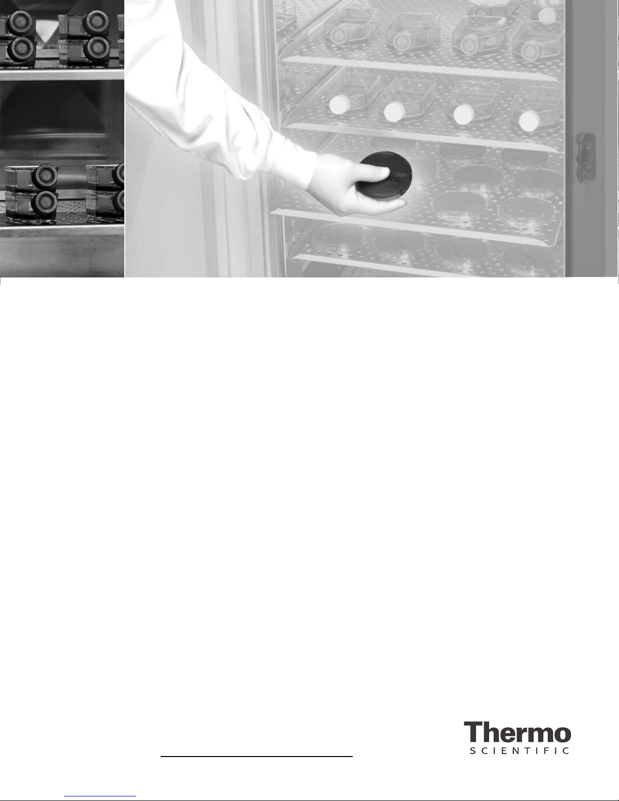
Model 310 Series DH Incubator viThermo Scientific
Table ofContents
Installation and Start-Up ......................................1-1
Control Panel Keys, Displays & Indicators . . . . . . . . . . . . . . . . . . . .1-2
Keypad Operation . . . . . . . . . . . . . . . . . . . . . . . . . . . . . . . . . . . . . . .1-3
Displays . . . . . . . . . . . . . . . . . . . . . . . . . . . . . . . . . . . . . . . . . . . . . . .1-4
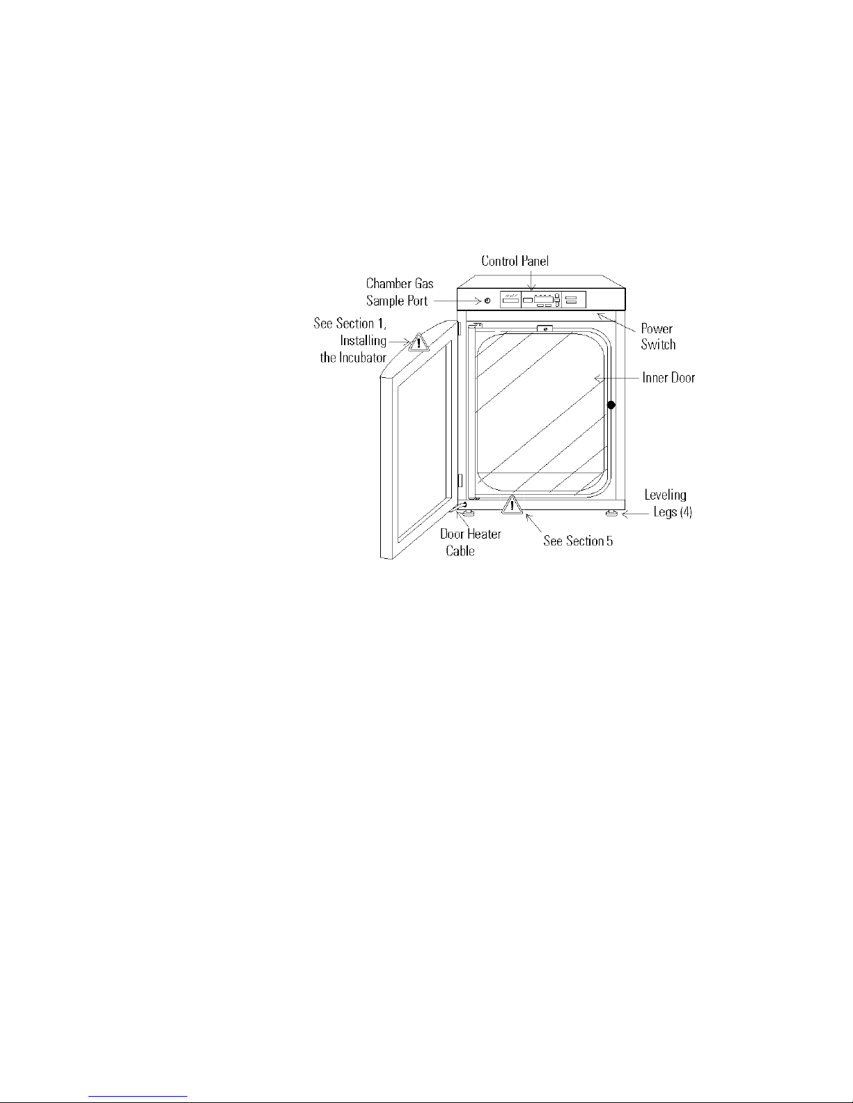
Installing the Incubator . . . . . . . . . . . . . . . . . . . . . . . . . . . . . . . . . . .1-4
Incubator Start-Up . . . . . . . . . . . . . . . . . . . . . . . . . . . . . . . . . . . . . .1-11
Calibration ..................................................2-1
Calibrating the Temperature . . . . . . . . . . . . . . . . . . . . . . . . . . . . . . .2-1
Calibrating the T/C CO2System . . . . . . . . . . . . . . . . . . . . . . . . . . . .2-2
Calibrating the Infrared CO2System . . . . . . . . . . . . . . . . . . . . . . . . .2-3
Calibrating Relative Humidity . . . . . . . . . . . . . . . . . . . . . . . . . . . . . .2-4
Configuration ................................................3-1
Turn the Audible Alarm ON/OFF . . . . . . . . . . . . . . . . . . . . . . . . . .3-1
Set an Access Code . . . . . . . . . . . . . . . . . . . . . . . . . . . . . . . . . . . . . . .3-1
Set a Low Temp Alarm Limit . . . . . . . . . . . . . . . . . . . . . . . . . . . . . .3-2
Enable the Low Temp Alarm to Trip Contacts . . . . . . . . . . . . . . . . .3-2
Set a Low CO2Alarm Limit . . . . . . . . . . . . . . . . . . . . . . . . . . . . . . . .3-3
Setting a High CO2Alarm Limit . . . . . . . . . . . . . . . . . . . . . . . . . . . .3-3
Enable CO2Alarms to Trip Contacts . . . . . . . . . . . . . . . . . . . . . . . .3-4
Set New Zero Number for T/C CO2Sensors . . . . . . . . . . . . . . . . . .3-4
Set New Span Number for T/C CO2Sensors . . . . . . . . . . . . . . . . . .3-5
Set a Low RH Alarm Limit . . . . . . . . . . . . . . . . . . . . . . . . . . . . . . . .3-5
Enable RH Alarms to Trip Contacts . . . . . . . . . . . . . . . . . . . . . . . . .3-6
Enable Temp/RH to be Displayed . . . . . . . . . . . . . . . . . . . . . . . . . . .3-6
Select Primary Tank w/ Gas Guard Option . . . . . . . . . . . . . . . . . . . .3-7
Disable the Gas Guard System . . . . . . . . . . . . . . . . . . . . . . . . . . . . . .3-7
Communications Address for RS485 . . . . . . . . . . . . . . . . . . . . . . . .3-8
Alarms ......................................................4-1
Temp Control Failure Alarm TMP CNTR ERR . . . . . . . . . . . . . . .4-2
Sensor Fault Alarms . . . . . . . . . . . . . . . . . . . . . . . . . . . . . . . . . . . . . .4-2
CO2 SNSR ERR . . . . . . . . . . . . . . . . . . . . . . . . . . . . . . . . . . . . . . . .4-2
IR AUTOZ ERR . . . . . . . . . . . . . . . . . . . . . . . . . . . . . . . . . . . . . . . .4-2
Section 1
Section 2
Section 3
Section 4