Titan L 221-0001 User manual

Betriebsanleitung
Kombiniertes Umreifungsgerät für Stahlband
Technische Daten:
Bandbreiten: 12.7, 16, 19 mm
Bandqualität: bis 900 N/mm²
Banddicke: 0,4-0,6 mm
Gewicht: 3.5 kg
Abmessung: 500x100x150 mm
H 221 DE 03/15
L 221 - 0001

ALLGEMEINES
Die Betriebsanleitung muß am Einsatzort des Gerätes verfügbar sein. Sie ist von allen Personen
zu lesen und anzuwenden, die mit dem Gerät arbeiten. Zu diesen Arbeiten zählen insbesondere
die Bedienung, die Störungsbehebung und die Wartung.
Neben der Betriebsanleitung und den im Verwenderland und an der Einsatzstelle geltenden
Regelungen zur Unfallverhütung sind auch die anerkannten fachtechnischen Regeln für
sicherheits- und fachgerechtes Arbeiten zu beachten.
SICHERHEITSVORSCHRIFTEN
Bestimmungsgemäße Verwendung
Dieses Gerät ist zum Umreifen von Paketen, palletierten Ladungen usw. bestimmt.
Das Gerät wurde für eine sichere Bedienung während des Umreifens entwickelt und gebaut.
Das Gerät ist für das Umreifen mit Verpackungsstahlbändern bestimmt.
Möglicher Mißbrauch
Das Umreifen mit Kunststoffband ist mit diesem Gerät nicht möglich.
Angewendete Normen und Spezifikationen:
DIN EN ISO 12100-1, DIN EN ISO 12100-2 “Sicherheit von Maschinen“
DIN EN 1010-1; DIN EN 1010-3 “Sicherheitstechnische Anforderungen für Konstruktion
und Bau von Druck und Papierverarbeitungsmaschinen“
Informieren Sie sich!
Vor dem Gebrauch des
Gerätes die
Betriebsanleitung
sorgfältig lesen.
Vorsicht:
Quetschgefahr!
Mit den Fingern nicht
in den Spannrad-
Bereich greifen.
Schützen Sie sich!
Beim Arbeiten Augen-
Gesichts- und
Handschutz (schnittfeste
Handschuhe) tragen.
Vorsicht:
Nur Packgut
umreifen!
Während des
Umreifens dürfen sich
keine Hände und
andere Körperteile
zwischen Band und
Packgut befinden.
Achtung:
Band springt auf!
Beim Durchschneiden
des Bandes den oberen
Teil festhalten und
abseits stehen.
Achtung:
Der untere Bandteil wird
aufspringen.
Verwenden Sie nur
Orginal-Ersatzteile!
Die Verwendung von
anderen als Original-
Ersatzteilen schließt
Garantieleistungen
und Haftpflicht aus.
Achtung:
Band kann reißen!
Beim Spannen kann das
Band reißen! Nicht in der
Flucht des Bandes
stehen.
H 221 DE 12/10

HANDHABUNG
H 221 DE 22/06
Mit der linken Hand beide Bänder exakt übereinander
liegend festhalten. Lüfthebel Pos 28 und Verschließhebel
Pos 17 mit der rechten Hand umfassen und
zusammendrücken. Beide Bänder bis zum Anschlag an
der Gehäusewand seitlich in das Gerät schieben. Dabei
muß das untere Band etwas aus dem Gerät herausragen.
Die zusammengedrückten Hebel loslassen.
Wenn erforderlich, große Bandschlaufe zuziehen. Hierbei
zieht die linke Hand die Bandschlaufe, die rechte Hand
umfaßt dabei den Lüfthebel.
Verpackungsstahlband von oben um das Packstück
führen. Bandende so weit durchziehen, bis es in der Mitte
des Packstückes unter dem Oberband liegt und eine
Handlänge hervorragt.
Die rechte Hand umfaßt den Spannhebel Pos 45 und
bewegt ihn hin und her. Das Band wird gespannt. Die
linke Hand umfaßt dabei den Verschließhebel Pos 17.
Nach Erreichen der gewünschten Bandspannung
Spannhebel Pos 45 zurückziehen, mit der rechten Hand
umfaßt halten und so den Gegenhalt für den
Verschließvorgang herstellen. Die linke Hand bewegt nun
den Verschließhebel Pos 17 zügig nach vorn bis zum
Anschlag am Gehäuse. Der Hülsenlosverschluß wird
gebildet. Gleichzeitig wird das Stahlband hinter dem
Verschluß abgeschnitten.
Spannhebel Pos 45 wieder in Ausgangslage
zurückbringen. Mit der rechten Hand Lüfthebel Pos 28
und Verschließhebel Pos 17 umfassen und
zusammendrücken. Das Gerät nach rechts aus der
Umreifung schwenken, abgeschnittenes Bandende mit
der linken Hand festhalten.

13 16 19
REINIGUNG DES GERÄTES
Schmutz und Abrieb beeinträchtigen die Funktion des Gerätes. Deshalb folgende Bereiche
wöchentlich säubern.
-Einlegeschlitz
-Hohlräume zwischen Ober- und Untermesser
-Spannrad
-Riffelschraube
Danach mit feinem handelsüblichem Sprühöl einölen.
Einstellen der Bandbreite
Zum Einstellen der Bandbreite wird die Bandführung Pos 31 eingestellt.
Zu diesem Zweck muß die Sicherungsscheibe Pos 40 mittels Schraubendreher
entfernt werden, danach die Transportwelle Pos 48 soweit zurückschieben,
daß die Bandführung frei liegt. Lüft- Pos 28 und Verschließhebel Pos 17
zusammendrücken und Bandführung seitlich abziehen. Die Bandführung
kann nun die entsprechenden 2 Bandbreitenteile Pos 41 erhalten wie die
nebenstehende Skizze zeigt. Für 13er Band muß die Stegbreite 3mm zum
Gerät zeigen, beim 16er der 2mm Steg und beim 19er benötigt man keine
Bandbreitenteile Pos 41. Nach der Montage der Bandbreitenteile wird die
Bandführung wieder eingesetzt. Anschließend die Sicherungsscheibe
Pos 40 aufstecken.
Da das Band an drei Punkten im Gerät geführt wird, müssen zusätzlich die vordere und hintere
Bandführung Pos 50 auf die Bandbreite eingestellt werden. Dazu die Befestigungsschrauben der
vorderen und hinteren Bandführung Pos 50 lösen und die Bandführung vom Gerät abnehmen,
die entsprechende Bandbreite einstellen (an den Stirnseiten sind die Bandbreiten 13, 16, 19 graviert.)
Die vordere und hintere Bandführung so aufsetzen, daß die Gravur der Bandbreite zum Band hin zeigt.
Abkerbeinstellung
Abstand zwischen Spannrad und
Riffelplatte
Bei unterschiedlichen Banddicken muß das
Kerbmesser auf die jeweilige Dicke eingestellt
werden.
Kontermutter Pos 32 lösen. Anschlagschraube
Pos 25 (Gewindestift mit Zapfen) mittels 3er
Imbusschlüssel im Uhrzeigersinn drehen =
weniger Schnittiefe, entgegen den Uhrzeigersinn
drehen = größere Schnittiefe. Kontermutter nach
erfolgter Einstellung fest anziehen.
Achtung! Auf dem Unterband dürfen nach dem
Einstellen keine oder nur geringe Abkerbspuren
sichtbar sein.
Der Abstand zwischen Spannrad Pos 30 und
Riffelplatte Pos 13 wurde Werksseitig auf 0,2
mm eingestellt. Die Stellschraube Pos 5
wurde mit Loctite 242 gesichert. Nach einem
Austauschen von Spannrad oder Riffelplatte
muß der Abstand überprüft und
gegebenenfalls mit der Stellschraube neu
justiert werden. Die Stellschraube ist erneut
mit Loctite 242 zu sichern.
Achtung! Transportrad und Riffelschraube
dürfen sich nicht berühren, sonst
verschleißen beide Teile vorzeitig.
H 221 DE 22/06

Pos
Benennung
Abmessung
Pos
Benennung
Abmessung
1
Gestell
28
Hebel
2
Gewindestift
M4x6
29
Nadelhülse
HK 2512
3
Gewindestift
M4x12
30
Transportrad
4
Gewindestift
M5x8
31
Bandführung
5
Gewindestift
M8x10
32
6kt. - Mutter
M6
6
Kerbstift
5x20
33
Obermesser
7
Zylinderstift
4m6x8
34
Kerbmesser
8
Zylinderstift
6m6x16
35
Zyl.-schraube
M4x10
9
Spannstift
5x12
36
Spannstift
3x6
10
Nadelhülse
DL 2012
37
Auswerfer
11
Zyl.-schraube
M3x8
38
Druckfeder
D-180-E
12
Untermesser
39
Wippe
13
Riffelplatte
40
Sicherungsscheibe
12
14
Ausheber
41
Bandbreitenteil
15
Exzenterwelle
42
Spannstift
4x8
16
Paßfeder
A5x5x16
43
Hülsenfreilauf
HFL 2530
17
Schneidhebel
44
Paßscheibe
25x35x0.5
18
Oberwerkzeug
45
Spannhebel
19
Nadelkranz
K25x33x20
46
Spannstift
5x24
20
Innenring
47
Hülsenfreilauf
HF 2520
21
Deckel
48
Transportwelle
22
Nadelbüchse
DLF 2016
49
Paßfeder
A5x5x18
23
Zyl.-schraube
M5x12
50
Bandführung v-h
24
Zyl.-schraube
M6x20
51
Zyl.-schraube
M5x8
25
Gewindestift
M6x40
52
Zugfeder
RZ-146 X
26
Zylinderstift
10m6x60
53
Firmenschild
(Option)
27
Zyl.-schraube
M5x25
H 221 DE 03/15
* Loctite 242
** Option

Instruction manual
Combined strapping tool for steel strap
Technical data:
Strap widths: 12.7, 16, 19 mm
Tensile strength: up to approx 900 N/mm²
Strap thicknesses:0,4 - 0,6 mm
Weight: 3.5 kg
Dimensions: 500x100x150 mm
H 221 GB 03/15
L 221 - 0001

GENERAL INFORMATION
The operating instructions must always be available at the place of operation of the strapping tool.
They must be read and observed by persons working with the strapping tool. This work specifically
includes operation, fault elimination and maintenance.
In addition to the operating instructions and the regulations for accident prevention effective in the
country of use and place of application, the recognised technical regulations for safety and proper
working must also be observed.
SAFETY INSTRUCTIONS
Use for the intended purpose
The tool is intended for strapping packages, pallet loads etc.
This tool was designed and manufactured for safe handling during the strapping operation.
The tool processes steel straps only.
Possible misuse
The use of plastic straps is not possible.
Standards applied and technical specifications:
DIN EN ISO 12100-1, DIN EN ISO 12100-2 “Safety of machinery“
DIN EN 1010-1, DIN EN 1010-3 “Safety requirements for the design and construction of print and paper
processing machines“
Inform yourself!
Read the operating
instructions carefully.
Caution!
Danger of squeezing!
Do not put your fingers
into the tension wheel
area.
Protect yourself!
When operating the tool,
wear eye, face and hand
protection (cut-proof
gloves).
Caution!
Only strap packed
goods!
Do not put hands or other
parts of the body between
the strap and the package
during the strapping
process.
Warning!
Strap will snap forward!
When cutting the strap, hold
the upper portion and stand
safely away from the strap.
Caution!
The lower strap will snap
forward.
Original spare parts
must be used
exclusively!
Use of spare parts which
are not manufactured by
Original voids any
warranty claims!
Warning!
Strap could break!
Do not stand in line with the
strap while it is tensioned.
The strap could break!
H 221 GB 12/10

Operating the tool
H 221 GB 22/06
With the left hand hold the upper and lower run of the strap
together. Both straps must be placed exactly on top of one
another. Grip and press lifting lever item 28 together with
the cutting lever item 17 with the right hand. Insert the steel
strap laterally until it strikes against the case wall, ensuring
that the lower run of strap projects slightly out of the tool at
the front. The right hand now releases the levers item 28
and item 17 which have been pressed together. If
necessary, tighten the great strap by hand.
Loop: The left hand pulls the strap loop, the right hand
grasps the lifting lever item 28.
Place steel strap from above around the package.
Pull through the strap end until it is in the center of the
package beneath the upper run of strap and juts out approx.
15 cm.
The right hand grasps the tension lever item 45 and moves
it back and forth to obtain the desired strap tension. At the
same time the left hand holds the cutting lever item17.
After having achieved the desired strap tension bring
tension lever item 45 back into its initial position. The right
hand remains there and provides support for the joining
process. The sealless joint is formed by pushing the cutting
lever item 17 forwards rapidly with the left hand until it
strikes against the case; the steel strap is simultaneously
cut off directly behind the joint.
Bring tension lever item 45 back into its initial position.
Grasp and press together lifting lever item 28 with cutting
lever item 17. Withdraw the tool from the package by a
rotary movement to the right side, keep the cut off strap
end in your left hand.

13 16 19
CLEANING THE TOOL
Dirt and chaff hamper the proper functioning of the tool.
For this reason the following areas should be cleaned once a week (blow off using compressed
air if possible):
-insertion slot,
-cavities between the upper and lower jaws,
-tensioning wheel,
-gripper plate.
Lubricate with fine conventional spray oil afterwards.
Adjusting strap
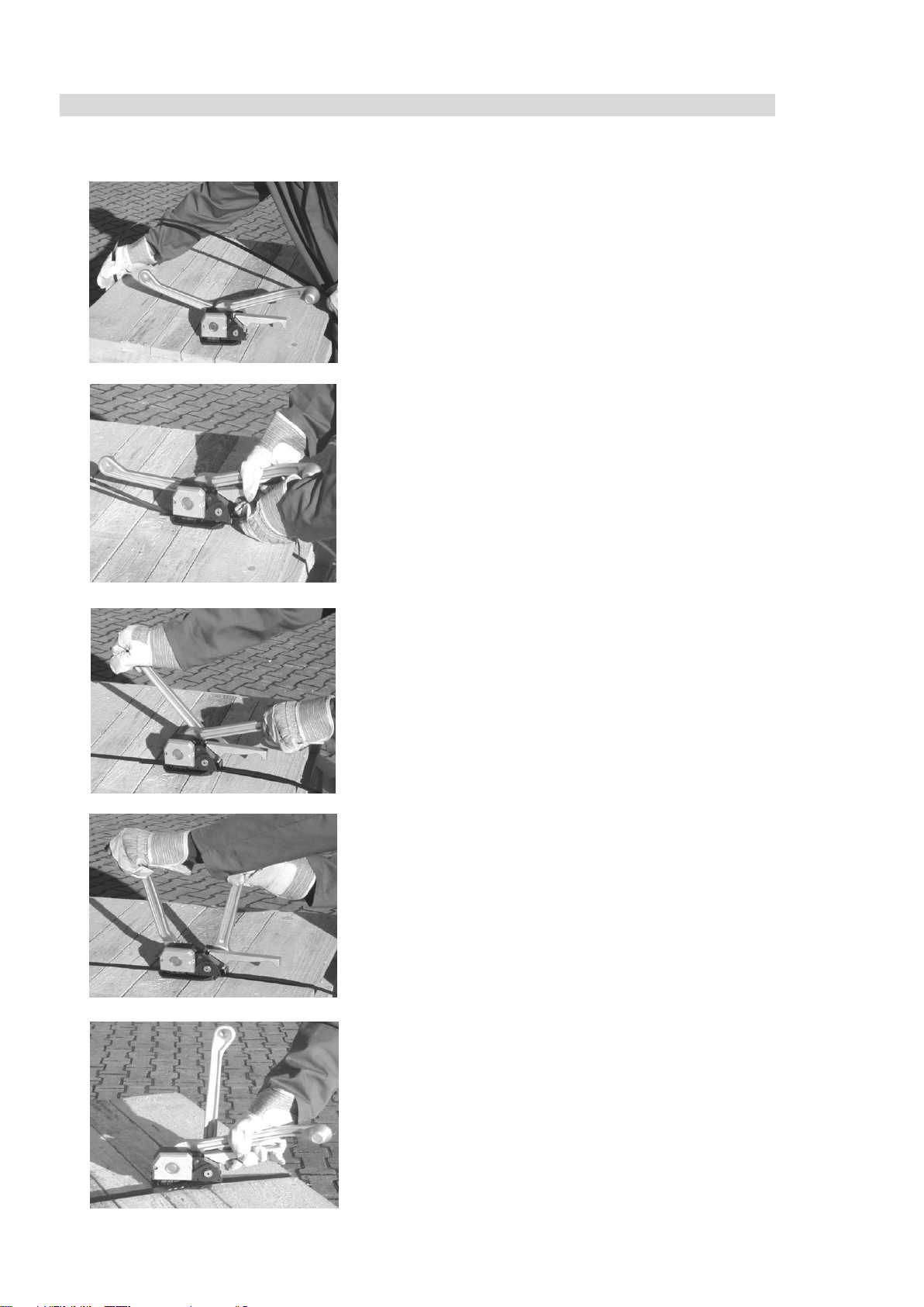
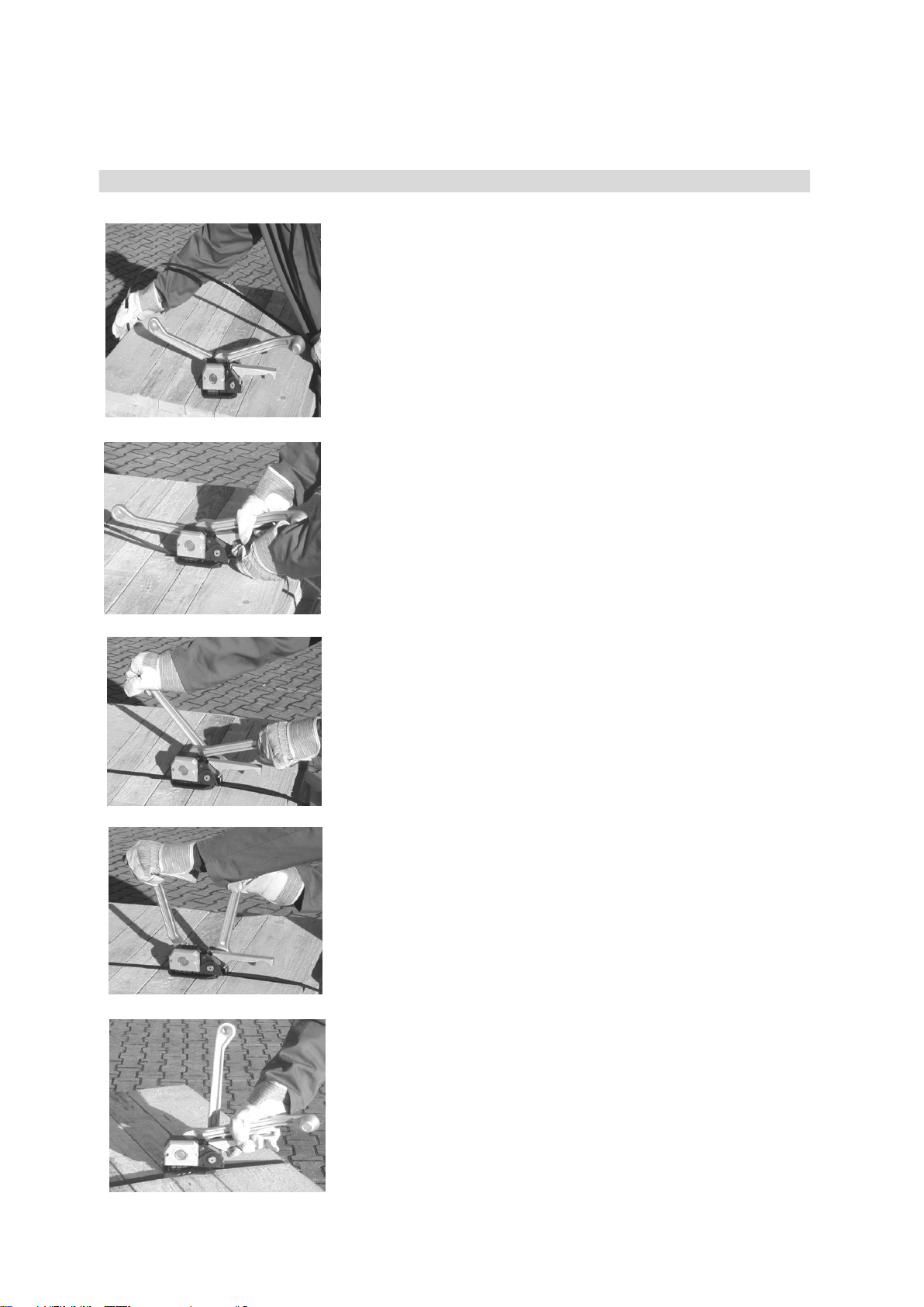
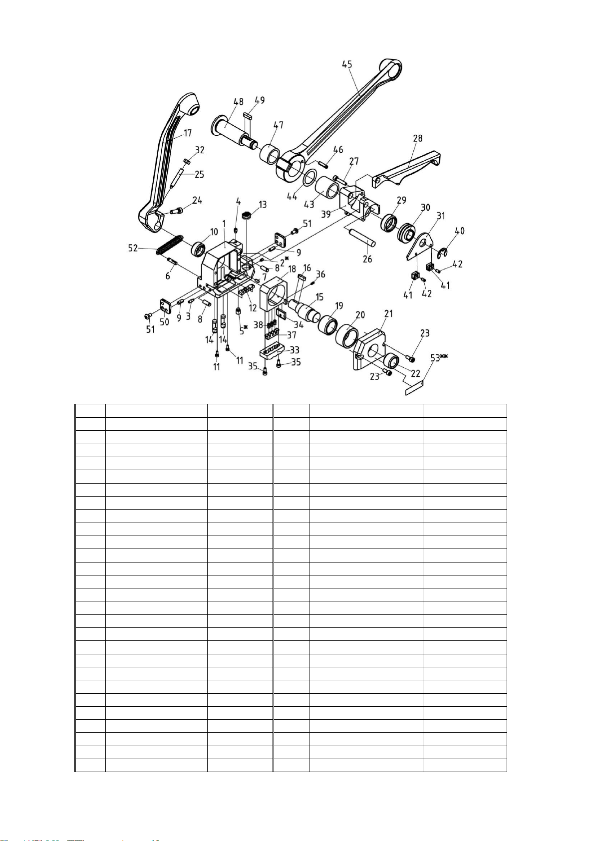
The correct strap width is set at item 31. For this purpose the safety
disc item 40 is to be removed with a screw driver, thereafter the feed
shaft item 48 is to be pushed back to make the strap guide accessible.
Compress lever item 28 and cutting lever item 17 and pull off the strap
guide. Provide the strap guide with the relevant 2 strap width spacers
item 41 such as shown on the sketch. For 13 mm strap the 3mm spacers,
for 16 mm the 2mm side point inside the tool, and for 19 mm strap no
spacer item 41 at all is required. After fitting the spacers the strap
guide is to be mounted again. Slip on safety disc item 40.As the strap
is being guided at three points in the tool, additionally the front and rear
strap guides item 50 are to be set to the correct strap widths. For this
purpose unscrew oval head screws of front and rear strap guides items 50,
remove strap guides, set the relevant widths (on the front sides the strap widths 13, 16,19
have been engraved.). Remount the strap guides in such a way that the engraved
widths point to the strapping.
Cutter adjustment
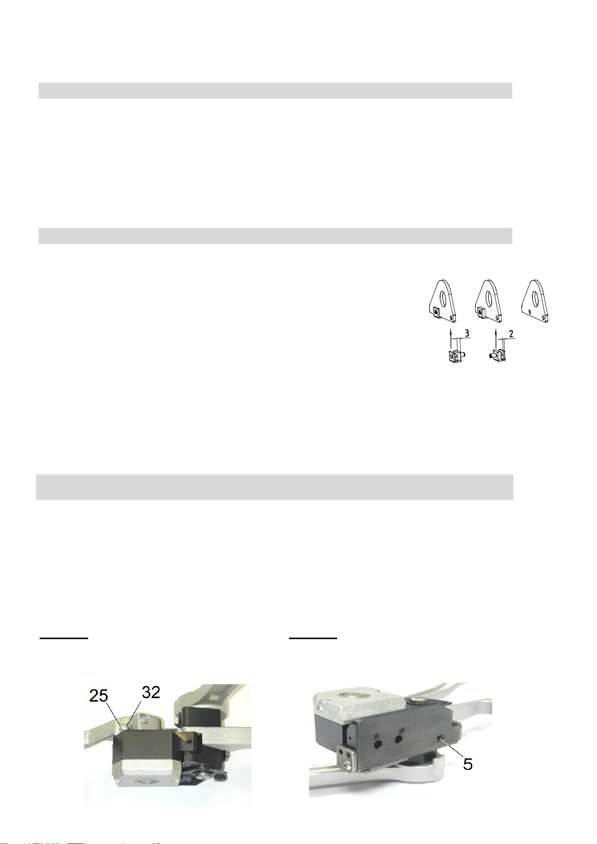
Distance between the feed wheel and the
gripper plate
The cutter has to be adjusted for the respective
thickness in the case of varying strap
thicknesses.
Release lock nut item 32. Turn stop screw item
25 (set screw with flat point) by means of a
socket spanner in clockwise direction = less
cutting depth; counter-clockwise = greater
cutting depth. Fasten locknut item 32 after
adjustment has been completed.
Note: After adjustment there should not be any,
or very few, signs of cutting on the lower strap.
The distance between tension wheel item 30
and gripper plate item 13 is set in our factory to
0,2 mm. The thread pin item 5 is secured with
Loctite 242. After replacing the tension wheel or
the gripper plate, the distance has to be
checked and possibly to be readjusted by
means of the thread pin. Then, the thread pin
has to be secured again with Loctite 242.
Note: The feed wheel and the gripper plate
must not come into contact with each other,
otherwise both parts will be subject to
premature wear
H 221 GB 22/06

Item
Description
Dimension
Item
Description
Dimension
1
Frame
28
Lever
2
Thread pin
M4x6
29
Needle sleeve
HK 2512
3
Thread pin
M4x12
30
Tension wheel
4
Thread pin
M5x8
31
Strap guide
5
Thread pin
M8x10
32
Hexagon nut
M6
6
Groove pin
5x20
33
Upper jaw
7
Cylinder pin
4m6x8
34
Cutter
8
Cylinder pin
6m6x16
35
Cylinder screw
M4x10
9
Dowel pin
5x12
36
Dowel pin
3x6
10
Needle sleeve
DL 2012
37
Ejector pin
11
Cylinder screw
M3x8
38
Pressure pin
D-180-E
12
Lower jaw
39
Rocker
13
Gripper plate
40
Safety disc
12
14
Ejector pin
41
Strap widths spacer
15
Eccentric shaft
42
Dowel pin
4x8
16
Feather key
A5x5x16
43
Sleeve freewheel
HFL 2530
17
Cutting lever
44
Adjusting washer
25x35x0.5
18
Upper jaw holder
45
Tension lever
19
Needle ring
K25x33x20
46
Dowel pin
5x24
20
Internal ring
47
Sleeve freewheel
HF 2520
21
Cover
48
Feed shaft
22
Needle bushing
DLF 2016
49
Feather key
A5x5x18
23
Cylinder screw
M5x12
50
Strap guide r-f
24
Cylinder screw
M6x20
51
Cylinder screw
M5x8
25
Thread pin
M6x40
52
Tension spring
RZ-146 X
26
Cylinder pin
10m6x60
53
Name plate
(option)
27
Cylinder screw
M5x25
H 221 GB 03/15
* Loctite 242
** option

Notice d´instructions
Appareil de cerclage combiné pour feuillard d'acier
Données techniques
Largeur du feuillard: 12.7, 16, 19 mm
Résistance: Jusqu’à environ 900 N/mm²
Epaisseurs du feuillard: 0,4-0,6 mm
Poids: 3.5 kg
Encombrement: 500x100x150 mm
H 221 FR 03/15
L 221 - 0001

INSTRUCTIONS GENERALES
Les instructions de service doivent constamment être à disposition sur le lieu d’utilisation de
l’appareil. Elles doivent être lues et appliquées par toutes les personnes qui sont chargées de
travaux sur l’appareil. Ces travaux comprennent en particulier le service, l’alimentation des
consommables, l’élimination des pannes et l’entretien.
En plus des instructions de service et des règlements pour la protection contre les accidents
valables dans le pays et à l’endroit d'utilisation, il faut également appliquer les règles de sécurité
techniques pour un travail professionnel et en sécurité.
INSTRUCTIONS DE SECURITÉ
Utilisation conforme
Cet appareil a été conçu pour le cerclage de paquets ou de palettes.
L’appareil a été conçu et construit pour assurer toute sécurité pendant le cerclage.
L’appareil est destiné au cerclage avec du feuillard d'acier.
Utilisation abusive
Le cerclage avec de la bande plastique est impossible avec cet appareil.
Normes et spécifications techniques utilisées:
DIN EN ISO 12100-1, DIN EN ISO 12100-2 “Sécurité des machines“
DIN EN 1010-1, DIN EN 1010-3 –Exigences techniques de sécurité pour la conception et la construction
des machines à imprimer et de transformation du papier“
Renseignez-vous !
Avant l’utilisation de l’appareil,
consultez soigneusement le
mode d'emploi.
Prudence :
Danger d'écrasement !
Ne touchez pas la
molette et
l’environnement avec les
doigts.
Protégez-vous !
Pendant le travail, portez des
protections pour les yeux, le
visage et les mains (gants de
sécurité).
Prudence :
Cercler uniquement le
paquet !
Ne mettez pas la main ou
d'autres parties du corps
entre le feuillard et
l’emballage
Attention !
Le feuillard saute !
En coupant le feuillard, restez
de côté et retenez bien le brin
supérieur du feuillard.
Attention :
Soyez prudent, le brin inférieur
sautera en avant.
N’utilisez que des
pièces de rechange
d'origine.
En cas contraire le
fournisseur peut refuser
les prestations de
garantie
Attention !
Le feuillard peut se rompre !
Ne restez jamais en ligne du
feuillard quand ce-ci est tendu,
car il peut se casser sous la
tension.
H 221 FR 12/10

MODE D'EMPLOI
H 221 FR 22/06
Saisir alors les 2 brins de feuillard de la main gauche
de façon à ce qu’ils se recouvrent parfaitement. Saisir
de la main droite la poignée 28 et le levier 17.
Refermer la main en serrant. Introduire les deux brins
dans l’appareil jusqu’en butée à l’ intérieur du carter.
Le brin inférieur doit dépasser de quelque peu de
l’appareil. Relâcher la pression de la poignée 28 et du
levier 17.
Si nécessaire réduire la boucle en tirant sur le feuillard
de la main gauche tandis que la main droite saisit la
poignée 28.
Le dévidoir étant derrière soi, passer le
feuillard par dessus le colis à cercler.Tirer
le brin de feuillard jusqu’à ce qu’il se
trouve au milieu du colis sous le brin
inférieur et dépassant l’appareil d’une
longueur de main.
Actionner de la main droite le levier 45
jusqu’à obtenir la tension voulue. La main
gauche saisissant le levier 17.
La tension désirée obtenue, remettre le
levier 45 dans sa position de départ. La
main droite y reste et fait ainsi le contre
poids durant I'opération de sertissage. La
main gauche actionne le levier 17 en avant
jusqu’à la butée du carter. Réalisation du
sertissage sans châpes et simultanément
coupe du brin de feuillard venant du
dérouleur.
Remettre le levier 45 dans sa position de
départ. Saisir de la main droite la poignée
28 et le levier 17. Refermer et serrer.
Dégager l’appareil vers la droite, retenir le
brin de feuillard coupé avec la main
gauche.

13 16 19
NETTOYAGE DE L'APPAREIL
La saleté et les déchets résultant de l'usure par frottement gênent le fonctionnement de l'appareil. Pour cette
raison, il est nécessaire
de procéder (dans la mesure du possible avec de l'air comprimé) au nettoyage hebdomadaire :
-de la fente d'insertion,
-des espaces entre le couteau supérieur et le couteau inférieur,
-de la molette de tension,
-de la pastille.
Procéder ensuite à la lubrification légère avec de l'huile de pulvérisation d'usage courant.
Réglage des largeurs de feuillard
Lorsque la largeur du feuillard change, on ajuste le guide 31. Pour ce but le
circlip 40 doit être démonté avec un tournevis., cela fait, pousser l’arbre de
transport 48 en arrière, afin que le guide soit accessible. Saisir et serrer la
poignée 28 et le levier de coupe 17 et enlever le guide lateralement. Alors, le
guide peut être pourvu des
2 entretoises 41 tel qu’il est montré sur le croquis à droite. Pour le feuillard de
13 mm de largeur les entretoises de 3mm doivent montrer à l’intérieur de
l‘appareil, pour le feuillard de16 mm les entretoises de 2mm doivent montrer à
l’intérieur de l’appareil, pour le feuillard de 19 mm on ne nécessite pas
d‘entretoise 41 Après le montage de l‘entretoise remonter le guide et remettre le
circlips 40.
Le feuillard étant guidé à trois points dans l‘appareil, il est nécessaire d’ajuster
aussi les 2 guides 50 (devant et arrière) selon la largeur du feuillard utilisé.
Pour cette raison détacher les vis des deux
guides 50 de devant et à l’arrière, détacher les guides, mettre les largeurs
désirées. (on a gravé
les largeurs 13, 16, 19 sur les fronts.). Mettre les guides de devant et à l’arrière de
manière que,
les côtés gravés donnent sur le feuillard.
Réglage du couteau 34
Ecart entre molette 30 et pastille 13 :
Le couteau doit être règle en fonction de
l’épaisseur du feuillard utilisé. Marche à
suivre : Desserrer l’écrou 32. Tourner la vis
25 dans le sens des aiguilles d’une montre
= faible profondeur de coupe; tourner la vis
dans le sens contraire= profondeur de
coupe plus importante. Resserrer la vis 32.
Attention : Le réglage est bon s´il n’y a pas
ou peu de traces de coupe sur le feuillard
inférieur.
L’écart entre la mollette 30 et la pastille 13 a
été réglé à l’usine à 0,2 mm. La vis 5 a été
fixée avec Loctite 242. Après l’échange de la
mollette ou de la pastille l’écart doit être
vérifíé et, si nécessaire, être ajusté de
nouveau par la vis. Dans ce cas on doit fixer
la vis de nouveau avec du Loctite 242.
Attention : La molette et la pastille ne
doivent pas se toucher : détérioration des 2
pièces.

Pos
Réf.
Désignation
Pos
Réf.
Désignation
1
Semelle
28
Poignée
2
Vis sans tête à six-pans creux
M4x6
29
Roulement à aiguilles
HK 2512
3
Vis sans tête à six-pans creux
M4x12
30
Molette
4
Vis sans tête à six-pans creux
M5x8
31
Guide
5
Vis sans tête à six-pans creux
M8x10
32
Écrou 6 pans
M6
6
Goupille
5x20
33
Poinçon
7
Goupille cylindrique
4m6x8
34
Couteau
8
Goupille cylindrique
6m6x16
35
Vis à tête cylindrique à six-
pans creux
M4x10
9
Goupille de serrage
5x12
36
Goupille de serrage
3x6
10
Roulement à aiguilles
DL 2012
37
Éjecteur
11
Vis à tête cylindrique à six-
pans creux
M3x8
38
Ressort
D-180-E
12
Matrice
39
Bascule de tension
13
Pastille
40
Circlips
12
14
Extracteur
41
Entretoise
15
Excentrique
42
Goupille de serrage
4x8
16
Clavette
A5x5x16
43
Carter de roue libre
HFL 2530
17
Levier de coupe
44
Rondelle d`epaisseur
25x35x0.5
18
Support de poinçon
45
Levier de tension
19
Bord aux aiguilles
K25x33x20
46
Goupille de serrage
5x24
20
Bague
47
Roue libre
HF 2520
21
Flasque
48
Arbre de transport
22
Roulement à aiguilles
DLF 2016
49
Clavette
A5x5x18
23
Vis à tête cylindrique à six-
pans creux
M5x12
50
Guides devant - arrière
24
Vis à tête cylindrique à six-
pans creux
M6x20
51
Vis à tête cylindrique à six-
pans creux
M5x8
25
Vis sans tête à six-pans creux
M6x40
52
Ressort
RZ-146 X
26
Goupille cylindrique
10m6x60
53
Plaque signalétique
(option)
27
Vis à tête cylindrique à six-
pans creux
M5x25
H 221 FR 22/06
H 221 FR 03/15
* Loctite 242
** option

Table of contents
Languages:
Other Titan Packaging Equipment manuals