TLV SS1NL User manual

FREE FLOAT TYPE STEAM TRAPS
FREISCHWIMMER KONDENSATABLEITER
PURGEURS DE VAPEUR À FLOTTEUR FERMÉ LIBRE
SS1NL/SS1NH/SS1VL/SS1VH
SS1NL/SS1NH/SS1VL/SS1VH
SS1NL/SS1NH/SS1VL/SS1VH
SS1VL/SS1VHSS1NL/SS1NH
Copyright (C) 2018 by TLV CO., LTD. All rights reserved.
INSTRUCTION MANUAL
Keep this manual in a safe place for future reference
EINBAU- UND BETRIEBSANLEITUNG
Gebrauchsanleitung leicht zugänglich aufbewahren
MANUEL D UTILISATION
Conserver ce manuel dans un endroit facile d'accès
Deutsch
Français
English

Introduction
Before beginning installation or maintenance, please read this manual to ensure correct use of
the product. Keep the manual in a safe place for future reference.
The all stainless steel Free Float steam traps of the SS1 series, with bimetal thermostatic air vent,
are suitable for a wide range of small to medium capacity applications up to 2.1 MPaG (300 psig),
such as steam mains, tracer lines, small process applications, etc. The traps discharge
condensate continuously and automatically, at a temperature slightly lower than saturation
temperature.
1 MPa = 10.197 kg/cm2, 1 bar = 0.1 MPa
For products with special specifications or with options not included in this manual, contact TLV
for instructions.
The contents of this manual are subject to change without notice.
Einführung
Bitte lesen Sie die Betriebsanleitung vor Einbau und Inbetriebnahme sorgfältig durch und be-
wahren Sie sie für späteren Gebrauch an einem leicht zugänglichen Ort auf.
Die Kugelschwimmer-Kondensatableiter der Serie SS1, komplett aus Edelstahl, mit thermischem
Bimetall Entlüfter können für kleine bis mittlere Anlagengrößen mit Betriebsdrücken bis 21 bar ü
eingesetzt werden. Sie eignen sich für Anwendungen, bei denen Kondensat mit geringer
Unterkühlung unter Sattdampftemperatur abgeleitet werden soll, z. B. für Leitungs-
entwässerung, Begleitheizung und kleine Prozessanlagen.
1 bar = 0,1 MPa
Wenden Sie sich an TLV für Sonderausführungen, die nicht in dieser Einbau- und Betriebs-
anleitung enthalten sind.
Wir behalten uns vor, den Inhalt dieser Betriebsanleitung ohne Ankündigung zu ändern.
Introduction
Veuillez lire attentivement ce manuel afin d’utiliser correctement le produit.
Nous vous recommandons de le garder dans un endroit sûr pour de futures consultations.
Les purgeurs de vapeur à flotteur fermé libre de la gamme SS1, avec purgeur d’air
thermostatique, sont entièrement en acier inoxydable, et peuvent être utilisés sur des applications
de petite capacité jusqu’à une pression de 21 bar. Ces modèles conviennent aux installations
évacuant le condensât à une température légèrement inférieure à la température de saturation,
telles les lignes de traçage, conduites de vapeur, et équipement pour procédés de tout genre.
1 bar = 0,1 MPa
Pour tout produit aux spécifications particulières ou comportant des options non reprises dans ce
manuel, veuillez contacter TLV.
Le contenu de ce manuel est sujet à modifications sans préavis.
1
Deutsch
Français
English
English
1. Safety Considerations
―2―
• Read this section carefully before use and be sure to follow the instructions.
• Installation, inspection, maintenance, repairs, disassembly, adjustment and valve
opening/closing should be carried out only by trained maintenance personnel.
• The precautions listed in this manual are designed to ensure safety and prevent equipment
damage and personal injury. For situations that may occur as a result of erroneous handling,
three different types of cautionary items are used to indicate the degree of urgency and the
scale of potential damage and danger: DANGER, WARNING and CAUTION.
• The three types of cautionary items above are very important for safety; be sure to observe
all of them, as they relate to installation, use, maintenance, and repair. Furthermore, TLV
accepts no responsibility for any accidents or damage occurring as a result of failure to
observe these precautions.
Indicates an urgent situation
which poses a threat of
death or serious injury.
Indicates that there is a
potential threat of death
or serious injury.
WARNING
CAUTION
WARNING
DANGER CAUTION
Indicates that there is a
possibility of injury or equip-
ment/product damage.
NEVER apply direct heat to the float. The float may explode due to
increased internal pressure, causing accidents leading to serious injury
or damage to property and equipment.
Install properly and DO NOT use this product outside the
recommended operating pressure, temperature and other specification
ranges. Improper use may result in such hazards as damage to the product
or malfunctions, which may lead to serious accidents. Local regulations
may restrict the use of this product to below the conditions quoted.
Take measures to prevent people from coming into direct contact
with product outlets. Failure to do so may result in burns or other injury
from the discharge of fluids.
DO NOT use this product in excess of the maximum operating
pressure differential. Such use could make discharge impossible.
When disassembling or removing the product, wait until the internal
pressure equals atmospheric pressure and the surface of the
product has cooled to room temperature. Disassembling or removing
the product when it is hot or under pressure may lead to discharge of
fluids, causing burns, other injuries or damage.
Be sure to use only the recommended components when repairing
the product, and NEVER attempt to modify the product in any way.
Failure to observe these precautions may result in damage to the product
or burns or other injury due to malfunction or the discharge of fluids.
Do not subject this product to condensate loads that exceed its
discharge capacity. Failure to observe this precaution may lead to
condensate accumulation upstream of the trap, resulting in reduced
equipment performance or damage to the equipment.
Use only under conditions in which no freeze-up will occur. Freezing
may damage the product, leading to fluid discharge, which may cause
burns or other injury.
Use under conditions in which no water hammer will occur. The
impact of water hammer may damage the product, leading to fluid
discharge, which may cause burns or other injury.
Deutsch
―3―
1. Sicherheitshinweise
• Bitte lesen Sie dieses Kapitel vor Beginn der Arbeiten sorgfältig durch und befolgen Sie die
Vorschriften.
• Einbau und Ausbau, Inspektion, Wartungs- und Reparaturarbeiten, Öffnen und Schließen von
Armaturen, Einstellung von Komponenten, dürfen nur von geschultem Wartungspersonal
vorgenommen werden.
• Die Sicherheitshinweise in dieser Einbau- und Betriebsanleitung dienen dazu, Unfälle,
Verletzungen, Betriebsstörungen und Beschädigungen der Anlagen zu vermeiden.
Für Gefahrensituationen, die durch falsches Handeln entstehen können, werden drei
verschiedene Warnzeichen benutzt: GEFAHR; WARNUNG; VORSICHT.
• Diese drei Warnzeichen sind wichtig für Ihre Sicherheit. Sie müssen unbedingt beachtet werden,
um den sicheren Gebrauch des Produktes zu gewährleisten und Einbau, Wartung und
Reparatur ohne Unfälle oder Schäden durchführen zu können. TLV haftet nicht für Unfälle oder
Schäden, die durch Nichtbeachtung dieser Sicherheitshinweise entstehen.
Bedeutet, dass eine unmittel-
bare Gefahr für Leib und
Leben besteht.
Bedeutet, dass die
Möglichkeit der Gefahr für
Leib und Leben besteht.
VORSICHT
WARNUNG
GEFAHR
WARNUNG
VORSICHT
Bedeutet, dass die Möglichkeit
von Verletzungen oder Schäden an
Anlagen oder Produkten besteht.
Die Schwimmerkugel darf NICHT ERHITZT werden, da sie infolge
erhöhten Innendruckes platzen kann, was schwere Unfälle und
Verletzungen oder Beschädigung von Anlagen zur Folge hat.
Die Einbauhinweise beachten und die spezifizierten Betriebsgrenzen
NICHT ÜBERSCHREITEN. Nichtbeachtung kann zu Betriebsstörungen
oder Unfällen führen. Lokale Vorschriften können zur Unterschreitung der
angegebenen Werte zwingen.
In sicherer Entfernung von Auslassöffnungen aufhalten und andere
Personen warnen, sich fernzuhalten. Nichtbeachtung kann zu
Verletzungen durch austretende Fluide führen.
Nur in frostsicherer Umgebung einsetzen. Einfrieren kann das Produkt
beschädigen, was zu Verbrennungen oder Verletzungen durch
austretende Fluide führt.
Nur an Stellen einbauen, an denen kein Wasserschlag eintreten
kann. Wasserschlag kann das Produkt beschädigen und zu
Verbrennungen oder Verletzungen durch austretende Fluide führen.
Das Produkt nicht bei Durchsatzmengen über der Nenn-
durchsatzleistung betreiben. Nichtbeachtung kann zu Kondensatrück-
stau führen wodurch die Leistung der Anlage beeinträchtigt, oder deren
Beschädigung verursacht wird.
Maximalen Differenzdruck NICHT ÜBERSCHREITEN,
da sonst die Kondensatableitung unmöglich werden kann (Blockage).
Vor Öffnen des Gehäuses und Ausbau von Teilen warten, bis der
Innendruck sich auf Atmosphärendruck gesenkt hat und das
Gehäuse auf Raumtemperatur abgekühlt ist. Nichtbeachtung kann zu
Verbrennungen oder Verletzungen durch austretende Fluide führen.
Zur Reparatur nur Original-Ersatzteile verwenden und NICHT
VERSUCHEN, das Produkt zu verändern. Nichtbeachtung kann zu
Beschädigungen führen, die Betriebsstörungen, Verbrennungen oder
andere Verletzungen durch austretende Fluide verursachen.
1. Règles de sécurité
• Lire attentivement cette notice avant l'utilisation et suivre les instructions.
• Tout installation, inspection, entretien, réparation, démontage, ajustement et
ouverture/fermeture de vanne doit être fait uniquement par une personne formée à l’entretien.
• La liste des précautions à prendre est établie afin d'assurer votre sécurité et de prévenir des
dégâts matériels et/ou des blessures sérieuses. Dans certaines situations causées par une
mauvaise manipulation, trois indicateurs sont utilisés afin d'indiquer le degré d'urgence,
l'échelle du dommage potentiel et le danger : DANGER, AVERTISSEMENT et ATTENTION.
• Ces 3 indicateurs sont importants pour votre sécurité ; observez les précautions de sécurité
énumérées dans ce manuel pour l'installation, l'utilisation, l'entretien et la réparation du produit.
TLV n'accepte aucune responsabilité en cas d'accident ou de dommage survenant à la suite
d'un non-respect de ces précautions.
Indique une situation
d'urgence avec risque de
mort ou de blessure grave.
Indique une situation
pouvant entraîner la mort ou
des blessures graves.
AVERTISSEMENT
ATTENTION
AVERTISSEMENT
DANGER
ATTENTION
Indique un risque de blessure
ou de dégât matériel au
produit et/ou aux installations.
Installer le produit correctement et NE PAS l’utiliser en dehors de la
pression et de la température maximales de fonctionnement, ni en
dehors des autres plages spécifiées. Une telle utilisation peut entraîner
des dommages au produit ou des dysfonctionnements, ce qui peut
provoquer des brûlures ou autres blessures. Il se peut que des règlements
locaux limitent l'utilisation du produit en-deçà des spécifications indiquées.
NE JAMAIS appliquer de chaleur directe au flotteur. Le flotteur pourrait
exploser suite à une pression interne accrue et causer des accidents
pouvant entraîner des blessures sérieuses ou des dégâts matériels.
Prendre les mesures appropriées afin d’éviter que des personnes
n’entrent en contact direct avec les ouvertures du produit. Le non-
respect de cette règle peut provoquer des brûlures ou autres blessures
sérieuses dues à l'écoulement des fluides.
Ne pas soumettre
ce produit
à des charges de condensât
supérieures à sa capacité d'expulsion. Le non-respect de cette consigne
peut engendrer une accumulation de condensât en amont du purgeur et
réduire les performances des installations, voire les endommager.
En cas de démontage ou de manipulation du produit, attendre que
la pression interne soit égale à la pression atmosphérique et que la
surface du produit soit complètement refroidie. Le non-respect de
cette règle peut provoquer des brûlures ou autres dommages dus à
l'écoulement des fluides.
En cas de réparation, utiliser uniquement les composants spéci-
fiques du produit et NE JAMAIS ESSAYER de modifier le produit.
Le non-respect de cette règle peut entraîner des dommages au produit,
ou des brûlures et autres blessures sérieuses dues au dysfonctionnement
du produit ou à l'écoulement des fluides.
N’utiliser que dans des conditions où le gel ne se produit pas. Le gel
peut endommager le produit et provoquer l'écoulement des fluides, et
causer des brûlures ou autres blessures sérieuses.
Utiliser le produit dans des conditions où il n'y a aucun coup de
bélier. L'impact d'un coup de bélier peut endommager le produit et
provoquer l’écoulement des fluides, ainsi que des brûlures ou des
blessures graves.
NE PAS utiliser ce produit avec une pression différentielle
supérieure au maximum indiqué. Le non-respect de cette consigne
pourrait empêcher toute expulsion du condensât (blocage).
4
Français
SS1NL/SS1NH
Horizontal Horizontal Horizontal
SS1VL/SS1VH
Vertical Vertikal Vertical
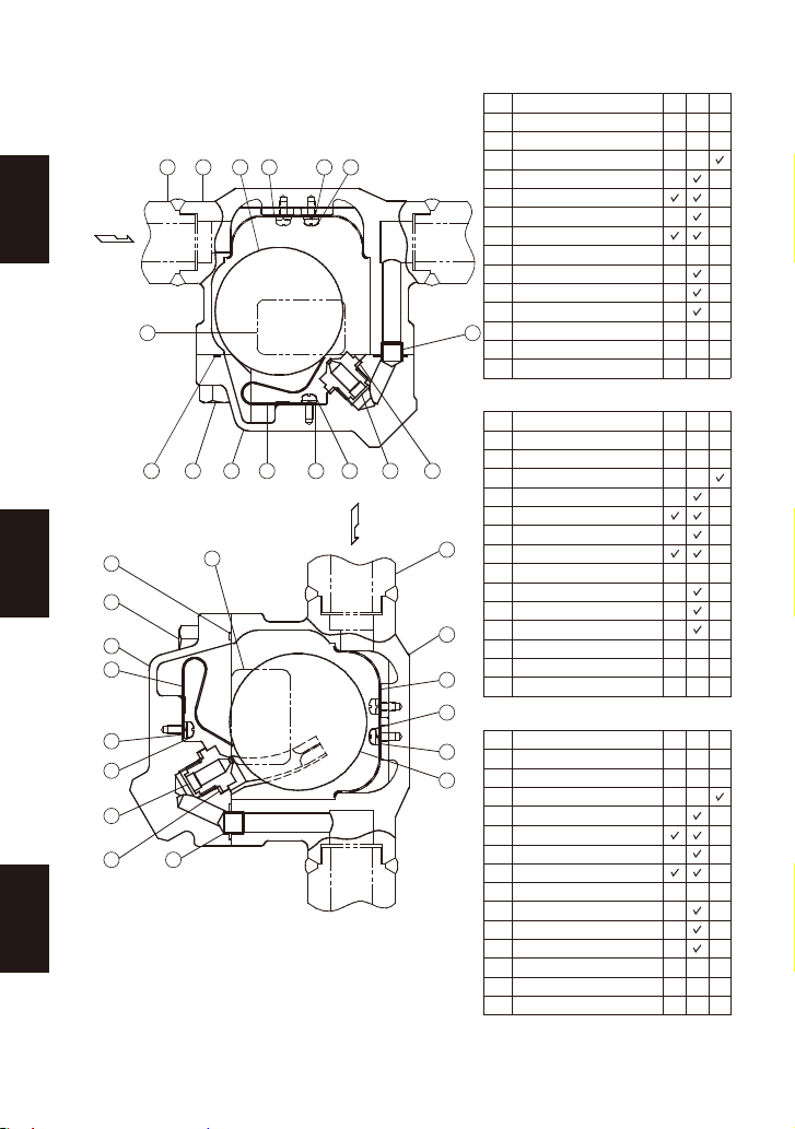
2. Configuration Aufbau Configuration
No.
1
2
3
4
5
6
7
8
9
10
11
12
13
14
Body
Cover**
Float
Orifice
Orifice Gasket
Screen
Cover Gasket
Cover Bolt
Bimetal Air Vent Strip
Screw
Spring Washer
Nameplate
Connector
Pipe/Flange
Description
** Includes attached float guides for
SS1VL/SS1VH
Nr.
1
2
3
4
5
6
7
8
9
10
11
12
13
14
Gehäuse
Gehäusedeckel**
Schwimmerkugel
Ventilsitz
Ventilsitzdichtung
Schmutzsieb
Gehäusedichtung
Gehäuseschraube
Bimetall Entlüfterbügel
Schraube
Federring
Typenschild
Verbindungshülse
Rohrstück/Flansch
Bauteil
** Einschließlich Schwimmerauflagen
SS1VL/SS1VH
N°
1
2
3
4
5
6
7
8
9
10
11
12
13
14
Corps
Couvercle**
Flotteur
Orifice
Joint d’orifice
Crépine
Joint du couvercle
Boulon du couvercle
Bilame purge d’air
Vis
Rondelle à ressort
Plaquette nominative
Tube guide
Tubulure/Bride
Désignation
** Guides de flotteur incorporés pour
le SS1VL/SS1VH
* M = Maintenance Kit; R = Repair Kit; F = Float; replacement
parts are available only in their respective kits
* W = Wartungssatz; R = Reparatursatz; S = Schwimmerkugel;
Ersatzteile werden nicht einzeln, sondern als Teil dieser
Ersatzteil-Sätze geliefert
* E = Jeu de pièces d'entretien ; R = Jeu de pièces de réparation ;
F = Flotteur ; les pièces de remplacement ne sont disponibles
que sous la forme de jeux de pièces
14 1 63
12 13
782 9 4 511 10
11 10
7
8
2
9
11
10
4
5
12 14
1
6
11
3
13
10
M*
-
-
-
-
-
-
-
-
-
-
-
-
R*
-
-
-
-
-
-
-
F*
-
-
-
-
-
-
-
-
-
-
-
-
-
W*
-
-
-
-
-
-
-
-
-
-
-
-
R*
-
-
-
-
-
-
-
S*
-
-
-
-
-
-
-
-
-
-
-
-
-
E*
-
-
-
-
-
-
-
-
-
-
-
-
R*
-
-
-
-
-
-
-
F*
-
-
-
-
-
-
-
-
-
-
-
-
-
5
Deutsch
Français
English

SS1NL/SS1NH SS1VL/SS1VH
3. Exploded View Einzelteile Pièces détachées
1110
13
2
8
9
4
5
3
7
6
1
1
7
1110
2
8
2
9
6
3
4
5
13
―6―
Deutsch
Français
English

4. Specifications Technische Daten Données techniques
Die Einbauhinweise beachten und die spezifizierten Betriebsgrenzen
NICHT ÜBERSCHREITEN. Nichtbeachtung kann zu Betriebsstörungen
oder Unfällen führen. Lokale Vorschriften können zur Unterschreitung der
angegebenen Werte zwingen.
VORSICHT
Installer le produit correctement et NE PAS l’utiliser en dehors des plages
spécifiées. En cas de dépassement des limites données, des dysfonc-
tionnements ou accidents pourraient survenir. Il se peut que des règlements
locaux limitent l'utilisation du produit en-deçà des spécifications indiquées.
ATTENTION
To avoid malfunctions, product damage, accidents or serious injury,
install properly and DO NOT use this product outside the specification
range. Local regulations may restrict the use of this product to below the
conditions quoted.
CAUTION
Refer to the product nameplate for detailed specifications.
Die technischen Daten stehen auf dem Typenschild.
Les données techniques sont inscrites sur la plaquette nominative.
* Maximum allowable pressure (PMA) and maximum allowable temperature (TMA) are
PRESSURE SHELL DESIGN CONDITIONS, NOT OPERATING CONDITIONS.
** "Valve No." is displayed for products with options. This item is omitted from the
nameplate when there are no options.
* Maximal zulässiger Druck (PMA) und maximal zulässige Temperatur (TMA) sind
AUSLEGUNGSDATEN, NICHT BETRIEBSDATEN.
** Die "Valve No." wird angegeben bei Typen mit Optionen. Bei Typen ohne Optionen bleibt
diese Stelle frei.
* Pression maximale admissible (PMA) et température maximale admissible (TMA) sont les
CONDITIONS DE CALCUL DU CORPS, PAS LES CONDITIONS DE FONCTIONNEMENT.
** Le "Valve No." est indiqué sur les modèles avec options. Ce numéro ne figure pas sur les
modèles sans options.
G Production Lot No.
Fertigungslos-Nr.
Lot de production n。
H Valve No.**
C Maximum Allowable Pressure*
Maximal zulässiger Druck*
Pression maximale admissible*
F Maximum Operating Temperature
Maximale Betriebstemperatur
Temp. de fonctionnement maximale
D
Maximum Allowable Temperature* TMA
Maximal zulässige Temperatur* TMA
Température maximale admissible* TMA
A Model
Typ
Modèle
E Maximum Differential Pressure
Maximaler Differenzdruck
Pression différentielle maximale
B Nominal Diameter
Größe/DN
Dimension/DN
A
B
D
F
G
G
D
E
B
C
A
C
F
H
E
H
Deutsch
Français
English
7
• Installation, inspection, maintenance, repairs, disassembly, adjustment
and valve opening/closing should be carried out only by trained
maintenance personnel.
• Take measures to prevent people from coming into direct contact with product outlets.
• Install for use under conditions in which no freeze-up will occur.
• Install for use under conditions in which no water hammer will occur.
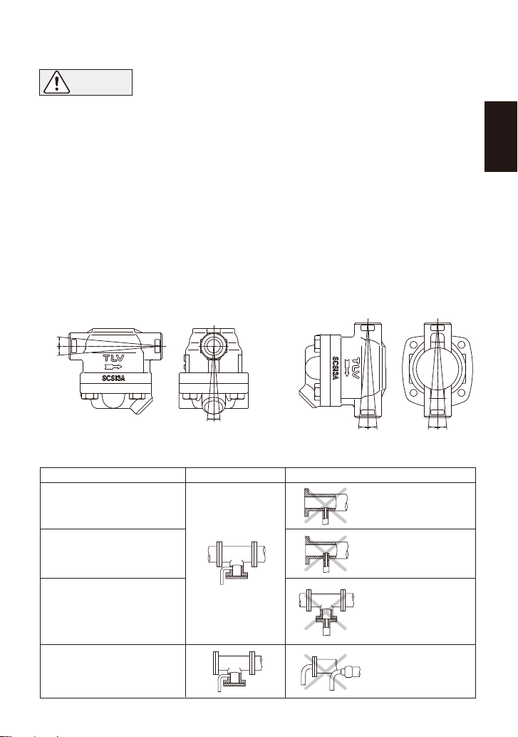
6. Piping Arrangement
Requirement
Install a catchpot with the
proper diameter.
Diameter is too
small.
Diameter is too
small and inlet
protrudes into pipe.
Rust and scale
flow into the trap
with the
condensate.
Condensate
collects in the
pipe.
Continued on the next page
Make sure the flow of
condensate is not
obstructed.
To prevent rust and scale
from flowing into the trap,
connect the inlet pipe
25 - 50 mm (1 - 2 in) above
the base of the T - pipe.
When installing on the
blind end, make sure
nothing obstructs the flow
of condensate.
Correct Incorrect
Allowable lnclination
SS1NL/SS1NH SS1VL/SS1VH
1.
Before installation, be sure to remove all protective seals.
2.
Before installing the trap, blow out the inlet piping to remove all dirt and oil.
3. Install the steam trap within the allowable inclination, as shown below. Also make sure that
the arrow mark on the body corresponds with the direction of flow.
4.
Install the trap in the lowest part of the pipeline or equipment so the condensate flows naturally
into the trap by gravity. The inlet pipe should be as short and have as few bends as possible.
5.
Support the pipes properly within 800 mm (2.5 ft) on either side of the trap.
6.
Install a bypass valve to discharge condensate, and inlet and outlet valves to isolate the trap in
the event of trap failure or when performing maintenance.
7.
Install a check valve at the trap outlet whenever more than one trap is connected to the
condensate collection pipeline.
8.
The use of unions is recommended to facilitate connection and disconnection of screwed
models.
5. Proper Installation
CAUTION
5˚5˚
5˚5˚ 5˚5˚5˚5˚
8
English

―9―
English
1. Is the pipe diameter suitable?
2. Has the trap been installed within the allowable inclination and with the arrow on the body
pointing in the direction of flow?
3. Has sufficient space been secured for maintenance?
4. Have maintenance valves been installed at the inlet and outlet? If the outlet is subject to
back pressure, has a check valve been installed?
5. Is the inlet pipe as short as possible, with as few bends as possible, and installed so that the
condensate will flow naturally down into the trap?
6. Has the piping work been done with the proper methods, as shown in the table on page 8?
Check to make sure that the pipes connected to the trap have been installed properly.
7. Operational Check
Normal: Condensate is discharged continuously with flash steam and the sound
of flow can be heard. If there is very little condensate, there is almost no
sound of flow.
Blocked: No condensate is discharged. The trap is quiet and makes no noise,
and the surface temperature of the trap is low.
Blowing: Live steam continually flows from the outlet and there is a continuous
metallic sound.
Live steam is discharged through the trap outlet together with the
condensate and there is a high-pitched sound.
A visual inspection can be carried out to aid in determining the necessity for immediate
maintenance or repair, if the trap is open to atmosphere. If the trap does not discharge to
atmosphere, use diagnostic equipment such as TLV TrapMan or TLV Pocket TrapMan.
White jet
containing
water droplets
Clear, slightly
bluish jet
(When conducting a visual inspection, flash steam is sometimes mistaken for steam leakage. For
this reason, the use of a steam trap diagnostic instrument such as TLV TrapMan is highly
recommended.)
Steam
Leakage:
Flash Steam Live Steam Leakage
Operational inspections should be performed at least twice per year, or as called for by trap
operating conditions. Steam trap failure may result in temperature drop in the equipment, poor
product quality or losses due to steam leakage.
8. Inspection and Maintenance
WARNING
NEVER apply direct heat to the float. The float may explode due to
increased internal pressure, causing accidents leading to serious injury or
property and equipment damage.
• Installation, inspection, maintenance, repairs, disassembly, adjustment
and valve opening/closing should be carried out only by trained
maintenance personnel.
• Before attempting to open the trap, close the inlet and outlet isolation
valves and wait until the trap has cooled completely. Failure to do so
may result in burns.
• Be sure to use the proper components and NEVER attempt to modify
the product.
CAUTION

Body, Cover
Gaskets
Air Vent Strip
Screen
Float
Orifice
Check inside for damage, dirt, grease, oil film, rust or scale
Check for warping or damage
Check for damage
Check for clogging, corrosion or damage
Check for deformation, damage, oil film or water inside
Check for rust, scale, oil film, wear or damage
Parts Inspection Procedure
Figure A Figure B
Screw &
Washer
Screen
Float Guides
Connector
Cover Gasket
Note: Do not change the
position of the float
guides. Tight sealing
cannot be guaranteed
if the float guides have
been moved out of
position.
Disassembly Reassembly
SS1NL/SS1VL:
Remove if damaged
SS1NH/SS1VH:
Remove gasket and clean sealing
surfaces of cover and body
Replace with a new gasket, do not apply
anti-seize
Replace with a new gasket if worn or
damaged
Coat threads with anti-seize and
tighten to the proper torque
Remove connector
Apply anti-seize to both sides and
replace with a new gasket
Remove with a socket wrench
Reinstall connector
Remove gasket and clean sealing
surfaces
Remove, being careful not to
scratch its polished surface
Part & No.
Cover 2
Cover Gasket 7
Connector 13
Remove the screw with a Philips
screwdriver, then remove the air
vent strip without bending
Reinstall air vent strip without bending;
tighten screw to the proper torque
Air Vent strip 9
(with Screw 10
and Washer 11)
Orifice 4
Orifice Gasket 5
Float 3
Remove with a socket wrench Coat threads with anti-seize and
tighten to the proper torque
Cover Bolt 8
Disassembly / Reassembly (to reassemble, follow procedures in reverse)
Remove carefully; take care to
prevent any damage to the float,
which may fall out when the cover
is removed
Make sure the sealing surfaces are clean
and then reattach; be careful not to bend
the float guides (SS1VL/SS1VH only);
(Fig. A)
Place inside the body (or on the cover), being
careful not to scratch its polished surface
Remove the 2 screws with a Philips
screwdriver, then remove the
screen without bending
Screen 6
(with Screws 10
and Washers 11)
Remove any scale build-up on the surface and
then reassemble (Fig. B); tighten screws to the
proper torque.
1 N.m 10 kg·cm
〜
〜
If drawings or other special documentation were supplied for the product, any torque given there
takes precedence over values shown here.
Cover Bolt 8
Tightening Torque and Distance Across Flats
mm (in)(lbf.ft)
N.m
(33)
45 17 ( )
Orifice 4
mm (in)(lbf.ft)
N.m
(15)
20 ( )
13
Screw 10
mm (in)(lbf.ft)
N.m
(0.22)
0.3 + +
32
21
/
2
1
/
English
10

Instructions for Plug / Holder Disassembly and Reassembly
The seal on the threaded plugs/holders found on TLV products is formed by a flat metal
gasket. There are various installation orientations for the gaskets, such as horizontal,
diagonal and downward, and the gasket may be pinched in the thread recesses during
assembly.
Instructions for Disassembly and Reassembly
①Remove the plug/holder using a tool of the specified
size (distance across flats).
②The gasket should not be reused. Be sure to
replace it with a new gasket.
③Clean the gasket surfaces of the plug/holder and the
product body using a rag and/or cleaning agents, then
check to make sure the surfaces are not scratched or
deformed.
④Coat both the gasket surface of the plug/holder and
the threads of the plug/holder with anti-seize, then
press the gasket onto the center of the gasket
surface of the plug/holder, making sure the
anti-seize affixes the gasket tightly to the
plug/holder. Check to make sure the gasket is not
caught in the recesses of the threads.
⑤Hold the plug/holder upside down to make sure that
the anti-seize makes the gasket stick to the
plug/holder even when the plug/holder is held
upside down.
⑥Screw the plug/holder by hand into the product body
while making sure that the gasket remains tightly
affixed to the center of the gasket surface of the
plug/holder. Make sure the entire gasket is making
contact with the gasket surface of the product body.
It is important at this point to make sure the gasket
is not pinched in the thread recesses of the
plug/holder.
⑦Tighten the plug/holder to the proper torque.
⑧Next, begin the supply of steam and check to make sure there is no leakage from the part
just tightened. If there is leakage, immediately close the inlet valve and, if there is a bypass
valve, take the necessary steps to release any residual pressure. After the surface of the
product cools to room temperature, repeat the procedure beginning from step ①.
Gasket
Do not pinch gasket
in thread recesses
Coat with anti-seize
Gasket Surface
③
④
⑤
⑥
English
11
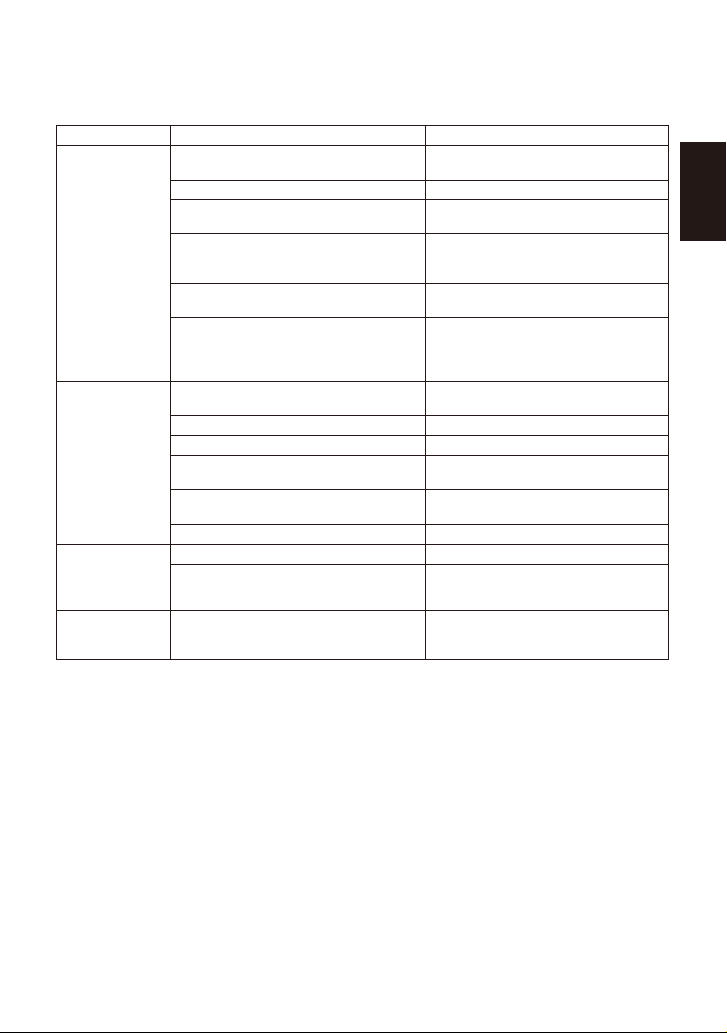
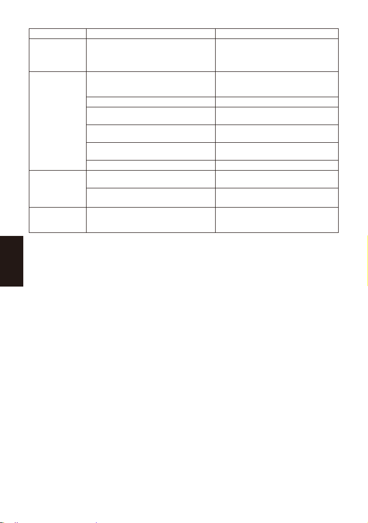
9. Troubleshooting
If the expected performance is unachievable after installation of the steam trap, read chapters 5
and 6 again and check the following points for appropriate corrective measures.
Problem
No condensate
is discharged or
discharge is
poor (blocked)
Steam is
discharged or
leaks from the
trap outlet
(blowing)
(steam leakage)
Steam leaks
from a place
other than the
trap outlet
Float is damaged or filled with
condensate
The trap operating pressure exceeds
the maximum specified pressure, or
there is insufficient differential pressure
between the trap inlet and outlet
Compare specifications and actual
operating conditions
Steam-locking has occurred
Flow exceeds trap’s rated capacity
Blowdown through the bypass or
close the trap inlet valve and allow
the trap to cool
Check specifications and reselect
trap suitable for actual flow
Clean
Deterioration of or damage to gaskets Replace with new gaskets
Float is
frequently
damaged
Water hammer occurs Examine the piping for
problems that can cause
water hammer
The Orifice is damaged Replace with new valve seat
Float is deformed or coated with scale Clean or replace the float
Trap is installed above the maximum
allowable inclination angle Correct the installation
Vibration of trap occurs Lengthen inlet piping, then fasten it
securely
The air vent strip is damaged Replace with a new air vent strip
Replace with new float
Cause Remedy
The float is sticking to the valve seat
Tighten to the proper torque
Orifice, screen or piping is
clogged with rust or scale
Rust and scale have accumulated
around the valve seat or under the float
Clean
Clean
Improper tightening torque for cover
was used
NOTE: When replacing parts with new, use the parts list on page 5 for reference, and replace with
parts from the respective replacement parts kits.
10. Product Warranty
1) Warranty Period: one year after product delivery.
2) TLV CO., LTD. warrants this product to the original purchaser to be free from defective
materials and workmanship. Under this warranty, the product will be repaired or replaced at
our option, without charge for parts or labor.
3) This product warranty will not apply to cosmetic defects, nor to any product whose exterior
has been damaged or defaced; nor does it apply in the following cases:
1. Malfunction due to improper installation, use, handling, etc., by other than TLV CO., LTD.
authorized service representatives.
2. Malfunctions due to dirt, scale, rust, etc.
3. Malfunctions due to improper disassembly and reassembly, or inadequate inspection and
maintenance by other than TLV CO., LTD. authorized service representatives.
4. Malfunction due to disasters or forces of nature.
5. Accidents or malfunctions due to any other cause beyond the control of TLV CO., LTD.
4) Under no circumstances will TLV CO., LTD. be liable for consequential economic loss or
damage or consequential damage to property.
12
English

1.
Vor dem Einbau die Transport-Schutzkappen entfernen.
2.
Vor Einbau Leitung durchblasen, um Öl und Verschmutzungen zu entfernen.
3. Die Kondensatableiter sind so einzubauen, dass die nachfolgend gezeigten Schräg-
lagentoleranzen nicht überschritten werden und der Pfeil auf dem Gehäuse in Durch-
flussrichtung zeigt.
4.
Die Zuführleitung sollte kurz sein, so wenig Krümmer wie möglich aufweisen und ist so zu
verlegen, dass das Kondensat durch Schwerkraftwirkung dem KA zufließen kann.
5.
Die Kondensatleitung im Abstand von maximal 800 mm vor und hinter dem KA abstützen.
6.
Für Wartung und Inspektion Absperrorgane vor und hinter dem Kondensatableiter, sowie eine
Umgehungsleitung zur Notentwässerung vorsehen.
7.
Falls die Auslassleitung in einen Tank oder eine Kondensatrückführleitung mündet, oder falls
mehrere Kondensatableiter an eine gemeinsame Leitung angeschlossen sind, muss ein
Rückschlagventil hinter jedem Kondensatableiter eingebaut werden.
8.
Bei Muffenanschluss wird empfohlen, Rohrverschraubungen vor und hinter dem
Kondensatableiter anzubringen.
5. Einbauhinweise
•
Einbau und Ausbau, Inspektion, Wartungs- und Reparaturarbeiten,
Öffnen/Schließen von Armaturen, Einstellung von Komponenten, dürfen nur
von geschultem Wartungspersonal vorgenommen werden.
•
In sicherer Enfernung von Auslassöffnungen aufhalten und andere Personen warnen, sich fern zu halten.
•
Kondensatableiter in frostsicherer Umgebung einbauen.
•
Kondensatableiter nur dort einbauen, wo kein Wasserschlag eintreten kann.
VORSICHT
6. Rohrleitungsführung
Vorschrift
Kondensatstutzen mit aus-
reichendem Durchmesser
einbauen.
Durchmesser
zu klein.
Durchmesser zu klein
und Abflussrohr ragt in
Rohrleitung hinein.
Rost und sonstige
Ablagerungen gelangen
mit dem Kondensat in
den Kondensatableiter.
Kondensat
sammelt sich in
Rohrleitung an.
Für ungehinderten
Kondensatzufluss
sorgen.
Um Rost und sonstige Ab-
lagerungen vom KA fernzuhalten
muss die Zuleitung 25~50 mm
über dem Deckel des Stutzens
angeschlossen werden.
Bei Einbau an Leitungsenden ist
die nebenstehende Anschlussart
vorzusehen, damit das Kondensat
ungehindert abfließen kann.
Richtig Falsch
Fortsetzung auf der nächsten Seite
Schräglagentoleranz
SS1NL/SS1NH SS1VL/SS1VH
5˚5˚
5˚5˚ 5˚5˚5˚5˚
13
Deutsch

1. Ist die Nennweite groß genug?
2. Wurde der Kondensatableiter horizontal, bzw. innerhalb der Schräglagentoleranz und mit
dem Pfeil in Durchflussrichtung eingebaut?
3. Ist genügend Platz für Wartungsarbeiten vorhanden?
4. Wurden vor und hinter dem Kondensatableiter Absperrarmaturen eingebaut? Falls
Gegendruck besteht, wurde ein Rückschlagventil eingebaut?
5. Ist die Zuleitung so kurz wie möglich, hat sie so wenig Krümmer wie möglich und kann das
Kondensat durch Schwerkraft zufließen?
6. Wurden die Rohrleitungen so ausgeführt, wie auf Seite 12 beschrieben?
Stellen Sie sicher, dass die Rohrleitungsarbeiten richtig ausgeführt wurden und dass der KA wie
beschrieben eingebaut wurde:
7. Funktionsprüfung
Normal: Kondensat wird kontinuierlich unter Bildung von Entspannungsdampf
abgeleitet. Ein entsprechendes Fließgeräusch ist zu hören. Bei geringer
Kondensatmenge ist dieses Geräusch ebenfalls geringer, oder kaum noch
wahrnehmbar.
Blockiert: Kondensatabfluss nicht feststellbar. Der Kondensatableiter macht kein
Geräusch und seine Oberflächentemperatur ist niedrig.
KA bläst: Sattdampf tritt kontinuierlich an der Auslassseite aus und ein metallisch
klingendes Geräusch ist hörbar.
Dampfverlust: Sattdampf, vermischt mit Kondensat tritt mit einem pfeifenden Geräusch
an der Auslassseite aus.
Falls der Kondensatableiter das Kondensat ins Freie abführt, können visuelle Inspektionen einen
Hinweis geben, ob sofortige Wartung oder Reparatur notwendig ist. An Kondensatrückführ-
leitungen angeschlossene Kondensatableiter können mit geeigneten Messgeräten, z. B. TLV
TrapMan oder TLV Pocket TrapMan geprüft werden.
Entspannungs-
dampf Dampfverlust
(Bei visueller Inspektion wird oft Entspannungsdampf mit Dampfverlust verwechselt. Daher wird
empfohlen, im Zweifel Messgeräte, z. B. TLV TrapMan zu verwenden).
Weißer
Strahl mit
Wassertr
öpfchen
Klarer, leicht
bl
äulicher Strahl
Es wird empfohlen, mindestens zweimal pro Jahr oder, je nach Betriebsweise, in kürzeren
Zeitabständen eine Inspektion durchzuführen.
8. Inspektion und Wartung
GEFAHR Um Unfälle und Verletzungen zu vermeiden, darf die Schwimmerkugel
NICHT ERHITZT WERDEN; da sie infolge erhöhten Innendrucks platzen
kann.
•
Einbau und Ausbau, Inspektion, Wartungs- und Reparaturarbeiten,
Öffnen/Schließen von Armaturen, Einstellung von Komponenten, dürfen nur
von geschultem Wartungspersonal vorgenommen werden.
• Vor dem Öffnen des Kondensatableiters sind die Absperrarmaturen auf
beiden Seiten zu schließen. Gehäuse auf Raumtemperatur abkühlen
lassen. Nichtbeachtung kann zu Verbrennungen führen.
• Zur Reparatur nur Original-Ersatzteile verwenden und NICHT
VERSUCHEN, das Produkt zu verändern.
VORSICHT
Deutsch
14

Gehäuse, Deckel
Dichtungen
Entlüfterbügel
Schmutzsieb
Schwimmerkugel
Ventilsitz
Auf Ablagerungen, Rost, Schmutz, Ölfilm prüfen
Auf Verformung oder Beschädigung prüfen
Auf Beschädigung prüfen
Auf Verstopfung, Ablagerungen, Beschädigung prüfen
Auf Verformung, Beschädigung oder Wasser in der Kugel prüfen
Auf Ablagerungen, Rost, Schmutz, Ölfilm prüfen
Überprüfung der Einzelteile
Vorsichtig herausnehmen, dabei
auf die Schwimmerkugel achten,
die herausfallen und beschädigt
werden könnte
In das Gehäuse (oder den Gehäu-
sedeckel) einsetzen, dabei die polierte
Oberfläche nicht zerkratzen
Sicherstellen, dass keine alten Dichtungsreste
an den Dichtflächen haften geblieben sind;
beim Aufsetzen des Deckels nicht die Kugel-
auflagen verbiegen (nur SS1VL/SS1VH); das
Schmutzsieb sicher in die im Deckel
eingefrästen Führungsnuten einsetzen (Abb. A)
Abbildung A Abbildung B
Schmutzsieb
Vorsicht: Die Kugelauflagen
nicht verstellen.
Dichter Abschluss
kann sonst nicht
gewährleistet
werden.
Ausbau Zusammenbau
Gewinde schmieren, Anzugsmoment beachten
Schraube lösen und
Entlüfterbügel herausnehmen,
ohne zu verbiegen
Dichtung erneuern, beide Seiten mit
Schmiermittel bestreichen
Ringschlüssel verwenden
Entlüfterbügel einsetzen, ohne zu
verbiegen; Anzugsmoment für
Schraube beachten
Dichtung entfernen und
Dichtflächen reinigen
Bauteil & Nr.
Gehäusedeckel 2
SSINL/SS1VL:
Abnehmen falls besch
ädigt Dichtung erneuern falls verformt oder
beschädigt
SS1NH/SS1VH:
Dichtung entfernen und Dichtflächen
von Gehäuse und Deckel reinigen
Dichtung erneuern, nicht mit
Schmiermittel bestreichen
Gehäusedichtung 7
Entlüfterbügel 9
(mit Schraube 10
und Federring 11)
Ventilsitz 4
Ventilsitzdichtung 5
Einsetzen
Herausnehmen
Verbindunsshülse 13
Verschmutzung/Ablagerungen entfernen
und in Gehäuse einsetzen (Abb. B);
Anzugsmoment für Schrauben beachten
Schrauben lösen und Sieb
herausnehmen ohne zu verbiegen
Schmutzsieb 6
(mit Schrauben 10
und Federringen 11)
Schwimmerkugel 3
Gabel- oder Ringschlüssel
verwenden Gewinde schmieren, Anzugsmoment
beachten
Gehäuseschraube 8
Ausbau und Einbau der Teile (Einbau erfolgt in umgekehrter Reihenfolge)
Vorsichtig herausheben,
feingeschliffene Oberfläche nicht
zerkratzen
Schraube &
Federring
Kugelführungen
Verbindungshülse
Gehäusedichtung
Gehäuseschraube 8
Anzugsmomente und Schlüsselweiten
mm
N.m
45 17
Ventilsitz 4
mm
N.m
20 13
Schraube 10
mm
N.m
0,3 +
Falls Zeichnungen oder andere spezielle Dokumente mit dem Produkt geliefert wurden, haben Angaben
über Anzugsmomente in diesen Unterlagen Vorrang vor den hier gezeigten Anzugsmomenten.
15
Deutsch

Aus- und Einbau-Anleitung für Entwässerungsstopfen
Die Gewindedichtung der Entwässerungsstopfen an TLV-Kondensatableitern besteht aus
einem flachen Metallring. Stopfen und Dichtung können in verschiedenen Lagen eingebaut
werden - horizontal, diagonal oder nach unten zeigend. Wird der Metallring dabei im
Gewinde gequetscht, verliert er seine Funktionstüchtigkeit.
Ausbau und Einbau
①Den Entwässerungsstopfen mit einem
Ringschlüssel gemäß der angegeben
Schlüsselweite ausschrauben.
②Einmal eingebaute Dichtungen nicht
wiederverwenden, sondern unbedingt ersetzen.
③Die Dichtflächen am Entwässerungsstopfen und am
Kondensatableiter mit einem Lappen o.ä. säubern
und auf einwandfreien Zustand prüfen (Kratzer).
④Sowohl die Dichtfläche, als auch das Gewinde
des Entwässerungsstopfens mit Schmiermittel
bestreichen. Dann den Dichtring zentriert auf die
Dichtfläche des Stopfens bringen, sodass der
Ring aufgrund des Schmiermittels am Stopfen
haftet. Der Dichtring darf nicht in eine
Gewindevertiefung verrutschen.
⑤Den Entwässerungsstopfen zur Probe der
Haftung des Dichtringes nach unten richten.
⑥Den Entwässerungsstopfen per Hand in den
Kondensat- ableiter eindrehen und dabei darauf
achten, dass der Dichtring zentriert auf der
Dichtfläche des Stopfens bleibt. Darauf achten,
dass der Dichtring nicht in das Gewinde
verrutscht, besonders wenn der Dichtring Kontakt
auch mit der Dichtfläche des Kondensatableiters
bekommt.
⑦Den Entwässerungsstopfen mit dem
ausgewiesenen Drehmoment festziehen.
⑧Führen Sie als nächstes eine Dichtigkeitsprüfung unter Dampf vor und achten besonders
auf das soeben eingebaute Bauteil. Falls Leckage auftritt sofort die Absperrarmatur an der
Einlassseite schließen und den Restdruck ablassen, falls eine Umgehungsleitung installiert
ist. Nach dem Ausgleich mit dem Umgebungsdruck und dem Abkühlen der
Produktoberflächen auf Raumtemperatur Aus- und Einbau ab ①wiederholen.
Dichtfläche
Dichtung
Dichtung nicht in das
Gewinde bringen
Mit Schmiermittel
versehen
③
④
⑤
⑥
Falls der Kondensatableiter nicht zufriedenstellend arbeitet, lesen Sie nochmals Kapitel 5 und 6.
Dann gehen Sie die nachfolgende Fehlerliste durch, um den Fehler zu orten und zu korrigieren.
Kondensat läuft
nicht ab, oder
Ableitung ist
ungenügend
Schwimmerkugel ersetzen
Reinigen
Auslegungsdaten überprüfen und
Kondensatableiter mit entsprechen-
der Leistung einsetzen
Kondensatmenge übersteigt die
Kapazität des Kondensatableiters
Umgehungsleitung durchblasen oder
Einlassventil schließen und KA
abkühlen lassen
Reinigen
9. Fehlersuche
Schwimmerkugel ist beschädigt
oder voll Wasser
Schwimmerkugel klebt am Ventilsitz
Dampfabschluss ist eingetreten
Ventilsitz, Schmutzsieb oder
Rohrleitungen sind verstopft mit
Schmutzablagerungen oder Rost
Symptom GegenmaßnahmenUrsachen
Fortsetzung auf der nächsten Seite
16
Deutsch
Kondensat läuft
nicht ab, oder
Ableitung ist
ungenügend
Dampfverlust
oder Durch-
blasen über
Auslassleitung
Der Betriebsdruck übersteigt den
maximal zulässigen Druck oder der
Differenzdruck zwischen Einlass und
Auslass ist zu niedrig
Prüfen, ob Auslegungsdaten
mit den wirklichen Betriebsdaten
übereinstimmen
Rost und Schmutz haben sich am
Ventilsitz oder unter der
Schwimmerkugel abgelagert
Reinigen
Häufiger Wasserschlag Rohrleitungen untersuchen und
mögliche Fehler beheben
Dichtungen sind abgenutzt oder
beschädigt Dichtungen ersetzen
Anzugsmoment von Gehäuseschrau-
ben zu gering Mit vorgeschriebenem
Anzugsmoment anziehen
Ventilsitz ist beschädigt Ventilsitz ersetzen
Schwimmerkugel ist beschädigt oder
verschmutzt Schwimmerkugel reinigen
oder ersetzen
Kondensatableiter innerhalb der
Schräglagentoleranz einbauen.
Kondensatableiter vibriert Einlassleitung verlängern,
Rohrleitungen besser unterstützen
Der Entlüfterbügel ist beschädigt Entlüfterbügel ersetzen
Schwimmer-
kugel ist oft
beschädigt
Leckage aus
Gehäuse
Kondensatableiter in zu großer
Schräglage eingebaut
Symptom GegenmaßnahmenUrsachen
ANMERKUNG: Wenn Bauteile ersetzt werden müssen, benutzen Sie die Bauteilliste auf Seite 5
und entnehmen Sie die beschädigten Teile aus den Ersatzteil-Sätzen.
10. Garantie
1) Garantiezeit: Ein Jahr nach Lieferung.
2) Falls das Produkt innerhalb der Garantiezeit, aus Gründen die TLV CO., LTD. zu vertreten
hat, nicht der Spezifikation entsprechend arbeitet, oder Fehler an Material oder Verarbeitung
aufweist, wird es kostenlos ersetzt oder repariert.
3) Von der Produktgarantie ausgenommen sind kosmetische Mängel sowie Beschädigungen
des Produktäußeren. Die Garantie erlischt außerdem in den folgenden Fällen:
1. Schäden, die durch falschen Einbau oder falsche Bedienung hervorgerufen werden.
2. Schäden, die durch Verschmutzungen, Ablagerungen oder Korrosion usw. auftreten.
3. Schäden, die durch falsches Auseinandernehmen und Zusammenbau, oder ungenügende
Inspektion und Wartung entstehen.
4. Schäden verursacht durch Naturkatastrophen und Unglücksfälle.
5. Unglücksfälle und Schäden aus anderen Gründen, die von TLV CO., LTD. nicht zu
vertreten sind.
4) TLV CO., LTD. haftet nicht für Folgeschäden.
17
Deutsch
1.
Ne pas oublier d’ôter toutes les étiquettes protectrices avant l’installation.
2.
Avant l
’
installation, souffler la tuyauterie d
’
entrée afin d
’
en retirer l
’
huile et les saletés.
3. Installer le purgeur en tenant compte des limites d’inclinaison, comme illustré ci-dessous.
S’assurer aussi que la flèche sur le corps pointe dans la direction du flux de condensât.
4.
Placer le purgeur de façon à ce que le condensât entre dans le purgeur par gravité. La conduite
d
’
entrée devrait être la plus courte et la moins courbée possible.
5.
Prévoir des supports de conduites de 0,8 m de chaque côté du purgeur.
6.
Installer une soupape en by-pass, ainsi que des soupapes d’entrée et de sortie, pour isoler le
purgeur en cas de défaillance ou d’entretien.
7.
Installer un clapet de retenue à la sortie du purgeur dans le cas où la conduite d’évacuation du
condensât mène à une citerne ou à une conduite de récupération. La même chose vaut dans le
cas où la conduite de collecte du condensât est raccordée à plusieurs purgeurs.
8.
L
’
utilisation de raccords est recommandée pour l
’
installation de la version taraudée.
5. Installation correcte
• Tout installation, inspection, entretien, réparation, démontage, ajustement
et ouverture/fermeture de vanne doit être fait uniquement par une
personne formée à l’entretien.
• Éviter que des personnes n’entrent en contact direct avec les ouvertures du produit.
• Utiliser le purgeur dans des conditions où le gel ne se produit pas.
• Ne pas utiliser le purgeur dans des conditions où des coups de bélier peuvent se produire.
ATTENTION
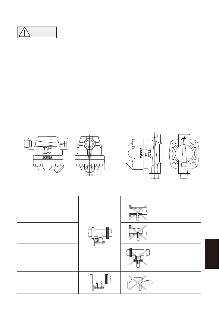
6. Disposition des conduites
Condition requise
Installer un pot de purge
d’un diamètre
adéquat.
Diamètre trop petit.
Diamètre trop petit et
l’entrée fait saillie
dans la conduite.
De la rouille et des
résidus entrent dans
purgeur avec le
condensât.
Le condensât
s’accumule dans
la conduite.
Vérifier que le flux de
condensât n’est pas
obstrué.
Pour empêcher l’entrée de
rouille et de résidus dans le
purgeur, connecter le tuyau
d’entrée 25-50 mm au-dessus
de la base du tuyau en T.
Lorsque le purgeur est installé
en bout de conduite, vérifier
que rien n’obstrue le flux de
condensât.
Correct Incorrect
Suite à la page suivante
Limites d’inclinaison
SS1NL/SS1NH SS1VL/SS1VH
5˚5˚
5˚5˚ 5˚5˚5˚5˚
18
Français

1. Est-ce que le diamètre de la conduite est adapté ?
2. Est-ce que le purgeur a été installé en respectant les limites d’inclinaison, et avec la flèche
sur le corps pointant dans la direction du flux ?
3. Est-ce qu’un espace suffisant a été prévu pour l’entretien ?
4. Est-ce que des vannes d’entretien ont été installées à l’entrée et à la sortie ? Si la sortie est
sujette à contre-pression, est-ce qu’un clapet de retenue a été installé ?
5. Est-ce que la conduite d’entrée est la plus courte et la moins courbée possible, et installée
de façon à ce que le condensât coule vers le purgeur naturellement ?
6. Est-ce que la tuyauterie à été faite correctement, tel qu’illustré dans le tableau en page 16 ?
Vérifier que les conduites raccordées au purgeur aient été installées correctement.
7. Inspection en état de marche
Normal : Le condensât est évacué de façon continue avec de la vapeur de
revaporisation, et le bruit du flux est audible. S’il n’y a que peu de
condensât, le flux n’est pratiquement pas audible.
Bloqué : Pas d’évacuation du condensât. Le purgeur ne fait pas de bruit et la
température de sa surface est basse.
Fuite totale : De la vapeur vive s’écoule continuellement par la sortie tout en faisant un bruit
métallique continu.
Fuite de
vapeur : De la vapeur vive est évacuée du purgeur avec le condensât tout en émettant
un son aigu.
Une inspection visuelle permet de déterminer si un entretien ou une réparation immédiate sont
nécessaires au cas où le purgeur est ouvert à l’atmosphère. Utiliser du matériel de diagnostic,
comme le TLV TrapMan ou le TLV Pocket Trapman, si le condensât n’est pas évacué dans
l’atmosphère.
(Lors d’une inspection visuelle, il est facile de confondre la présence de vapeur de revaporisation
avec une fuite de vapeur. Pour cette raison, l’utilisation d’un appareil de diagnostic comme le TLV
TrapMan est fortement recommandée.)
Vapeur de
revaporisation
Jet blanc contenant
des gouttelettes
d
’
eau
Fuite de
vapeur vive
Jet clair et
bleuâtre
Des inspections périodiques devraient être faites au moins deux fois par an, ou bien aux
intervalles habituels. Un purgeur de vapeur défectueux peut être à l’origine de pertes dues à des
fuites de vapeur.
8. Contrôle et entretien
AVERTISSEMENT
NE JAMAIS soumettre le flotteur directement à la chaleur. Le flotteur
pourrait exploser suite à une augmentation de la pression interne, et causer
des accidents pouvant entraîner des blessures sérieuses ou des dégâts aux
installations.
• Tout installation, inspection, entretien, réparation, démontage, ajustement
et ouverture/fermeture de vanne doit être fait uniquement par une
personne formée à l’entretien.
• Avant de vouloir ouvrir le purgeur, fermer les soupapes de sectionnement
à l’entrée et à la sortie du purgeur, et attendre qu’il soit complètement
refroidi. Le non-respect de ces consignes peut être à l’origine de brûlures
ou de blessures.
• Utiliser les composants appropriés et NE JAMAIS modifier le purgeur.
ATTENTION
19
Français
Other manuals for SS1NL
2
This manual suits for next models
3
Table of contents
Languages:
Other TLV Control Unit manuals


