TOORX MSX3000 User manual

Ed : 10/18 Rev : 00 Cod : GRLDTOORXMSX3000
INSTRUCTION

Table of Contents
S
pare parts list ...............................................................................................................
3
S
pare parts list ...............................................................................................................
4
S
pare parts list ...............................................................................................................
5
S
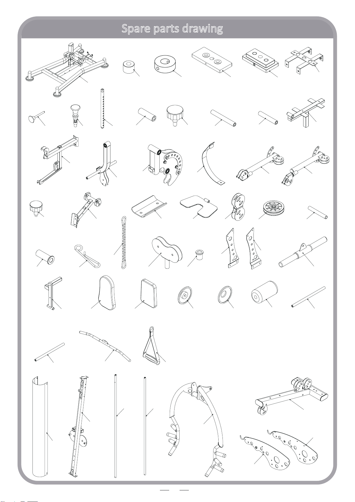
pare parts drawing .......................................................................................................
6
F
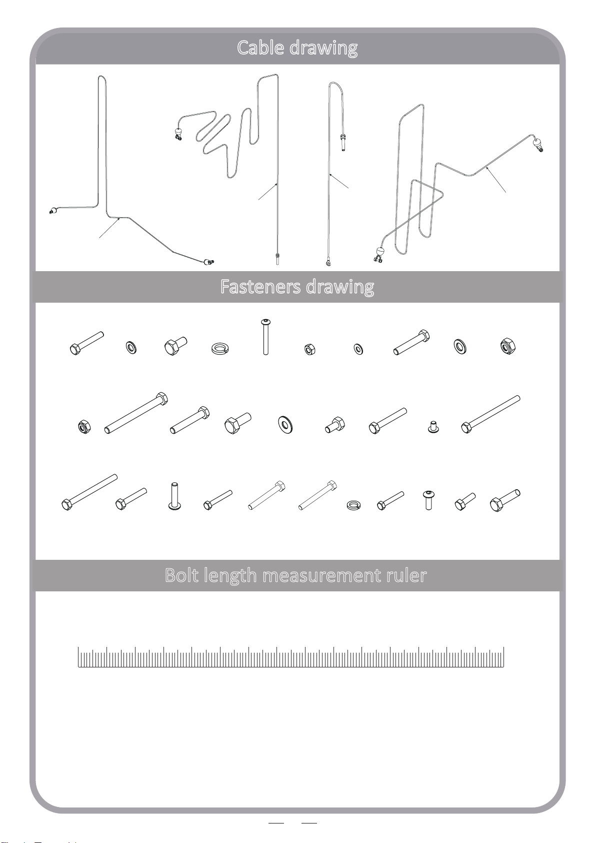
asteners drawing..........................................................................................................
7
A
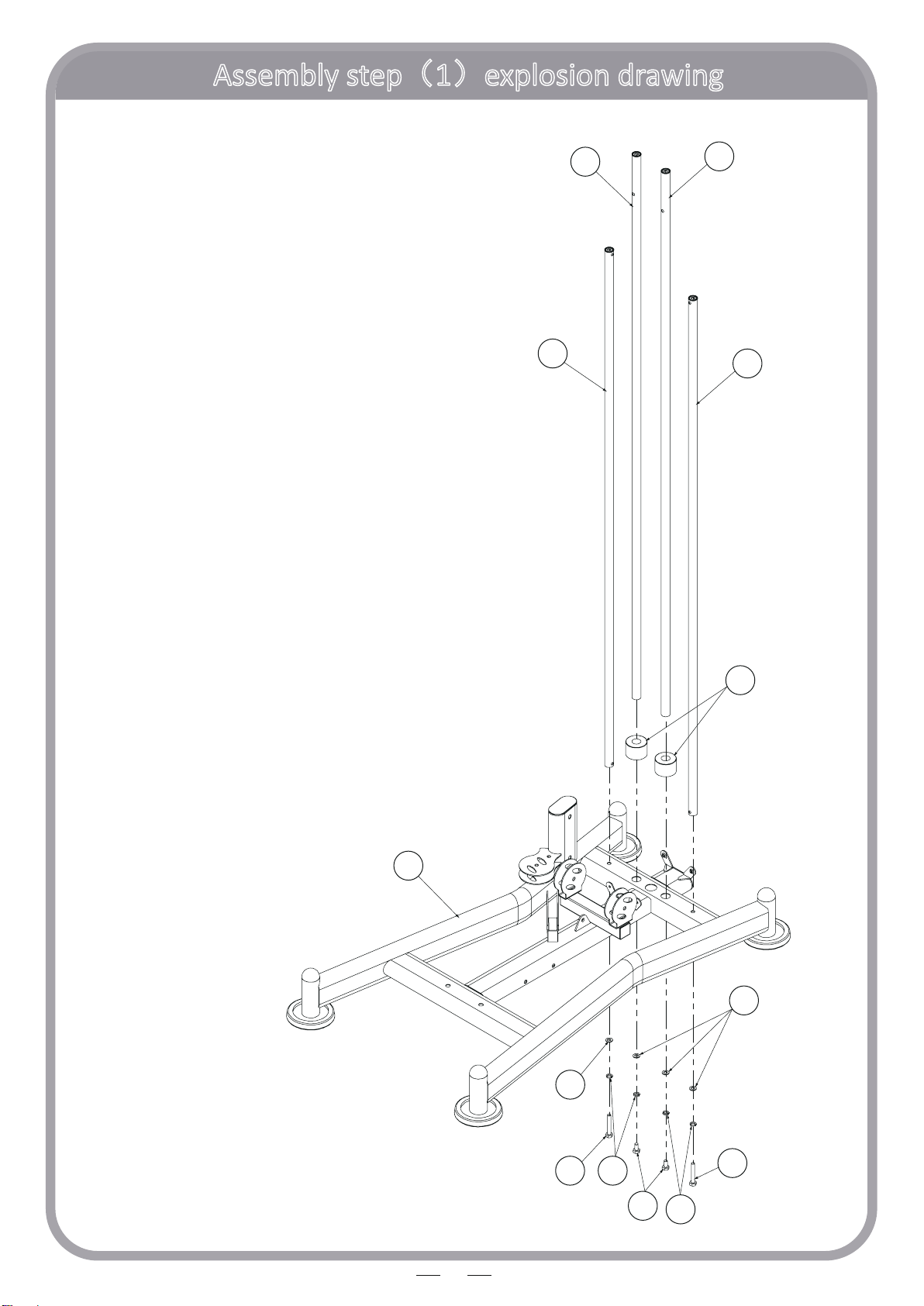
ssembly step(1)...................................................................................................8-
9
A
ssembly step(2)...............................................................................................10-1
1
A
ssembly step(3)...............................................................................................12-1
3
A
ssembly step(4)...............................................................................................14-1
5
A
ssembly step(5)...............................................................................................16-1
7
A
ssembly step(6)...............................................................................................18-1
9
A
ssembly step(7)...............................................................................................20-2
1
A
ssembly step(8)...............................................................................................22-2
3
A
ssembly step(9)...............................................................................................24-2
6
A
ssembly step(10).............................................................................................27-2
8
A
ssembly step(11).............................................................................................29-3
1
A
ssembly step(12).............................................................................................32-3
3
A
ssembly step(13).............................................................................................34-3
6
A
ssembly step(14).............................................................................................37-3
8
A
ssembly step(15).............................................................................................39-4
0
A
ssembly step(16).............................................................................................41-4
2
A
ssembly step(17).............................................................................................43-4
4
A
ssembly step(18).............................................................................................45-4
6
F
actory assembly spare parts list.................................................................................4
7
F
actory assembly steps ...........................................................................................48-5
5

Spare parts list
3
No. Descripon Note Qty.
1 ground frame 1
2 guide rodΦ25*1853 2
3 back support rodΦ259*1757.5 2
4 hexagon bolt M10*65 6
5 washer Φ10 78
6 hexagon bolt M10*20 8
7 spring washer Φ10 14
8 rubber cushionΦ60*Φ26*42 2
9 counter weight rubber cushionΦ60*Φ26*20 2
10 hexagon socket buon head bolt M8*70 2
11 lock nut M8 6
12 selector rod 92 KG 1
13 counter weight 6 KG 14
14 topmost counter weight 8 KG 1
15 washer Φ8 26
16 weight pin Φ10*100 1
17 lock pin 2
18 pull pin Φ10 2
19 hexagon bolt M12*70 4
20 washer Φ12 23
21 lock nut M12 11
22 front frame 1
23 lock nut M10 32
24 shield support frame 1
25 upper frame 1
26 hexagon bolt M12*130 3
27 right cover 1
28 lecover 1
29 hexagon bolt M12*75 4
30 hexagon bolt M10*25 2
31 axis of rotaonΦ17*57 1
32 seat cushion adjust frame 1
33 seat cushion tube 1

Spare parts list
4
No. Descripon Note Qty.
34 leg curl elbow tube 1
35 big washer Φ25*10*2.0 6
36 hexagon bolt M8*16 9
37 pull pin Φ12 1
38 sha Φ17*134 1
39 sha Φ17*100 1
40 front push holder 1
41 guard plate 1
42 front push arm 1
43 hexagon bolt M10*70 1
44 hexagon socket buon head bolt M10*16 2
45 right buerfly arm 1
46 lebuerfly arm 1
47 pulley support frame 1
48 reinforcing plate 1
49 footplate 1
50 hexagon bolt M10*130 6
51 hexagon bolt M10*115 2
52 hexagon bolt M10*45 19
53 hexagon socket buon head bolt M10*45 1
54 “-” shape pulley frame 2
55 pulley Φ95*26 27
56 connecng sleeve Φ14*100 1
57 pulley spacer Φ22*Φ10.5*45.5 4
58 lat pull cable L:4540mm 1
59 cable hook 1
60 9 link chain & snap hook 5
61 double pulley plate 1
62 middle cable L:1500mm 1
63 hexagon bolt M8*45 4
64 buerfly arm cable L:5375mm 1
65 hexagon bolt M10*75 2
66 hexagon bolt M10*85 1

5
Spare parts list
No.
Descripon
Note
Qty.
67
powder metallurgy sleeve
Φ10
2
68
lesupport plate
1
69
right support plate
1
70
low pull cable
L=3365mm
1
71
short bar
1
72
spring washer
Φ8
12
73
hexagon bolt
M8x40
4
74
back cushion adjustment frame
1
75
back cushion
1
76
seat cushion
1
77
hexagon socket buon head bolt
M8x25
6
78
sponge inner cap
6
79
sponge outer cap
6
80
sponge
Φ10x75
6
81
sponge rod
Φ25x480
1
82
sponge rod
Φ25x450
1
83
shield
2
84
long bar
1
85
handle belt
2
150
hexagon bolt
M8x25
1
162
hexagon bolt
M10x40
2

Spare parts drawing
6
1
9
12
13 14
25
23
42
28
34
32
18
17
24
47
60
57
68
84
71
61 67
85
74 75 76 81
82
79
78 80
37
83
48 49 54 55
69
56
59
33
31
45 46
40
38 39
41
27
16
8
22

7
58 64
70
62
Bolt length measurement ruler
Fasteners drawing
Cable drawing
0 1 6 7 8 9 10 11 12 13 14 152 3 4 5 cm
4 5 6 10
73
11
77
15
3023
20 21
19
50
51 52 63 65 66
29
26 3635 4443
72
7
53
162150

Assembly step(1)explosion drawing
8
8
7
7
1
4
4
5
5
6
3
3
2
2
No. Descripon Note Qty.
1 ground frame 1
2 guide rodΦ25*1853 2
3 back support rodΦ259*1757.5 2
4 hexagon bolt M10*65 2
5 washer Φ10 4
6 hexagon bolt M10*20 2
7 spring washer Φ10 4
8 rubber cushionΦ60*Φ26*42 2

Assembly step(1)drawing
9
Assembly step(1)assembly instrucon
1. Fix back support rod(3) on ground frame(1) using:
M10*65 hexagon bolt(4),Ф10 spring washer(7),Ф10 washer(5)
2
.Fix guide rod(2) on ground frame(1) using:
M10*20 hexagon bolt(6),Ф10 spring washer(7),Ф10 washer(5)
3
.Put rubber damper(8) on guide rod(2)
CAUTION: All bolts should be ghtening.

Assembly step(2)explosion drawing
10
14
Topmost counter weight (14)
Paral enlarged drawing
10
9
11
15
15
12
14
13
16
No. Descripon Note Qty.
9
counter weight rubber
cushion
Φ60*Φ26*20
2
10
hexagon socket buon
head bolt
M8*70
2
11 lock nut M8 2
12 selector rod 92 KG 1
13 counter weight 6 KG 14
14 topmost counter weight 8 KG 1
15 washer Φ84
16 weight pin Φ10*100 1

Assembly step(2)drawing
11
Assembly step(2)assembly instrucon
1. From guide rod top in turn put 14pcs counter weight(13), topmost counter weight(14);
among put topmost counter weight(14) on the top
2
.Remove the bolt from the topmost counter weight(14),then lower the selector rod(12)
intocounter weights central, final install the bolt back totopmost counter weight(12)
3
.Fix counter weight rubber cushion(9) in the topmost hole in guide rod using:
in each case-one M8*70 hexagon socket buon head bolt(10),twoФ8 washer(15)
and one M8 lock nut(11)
4
.Insert weight pin(16) intothe front of the second-to-boom counter weight
CAUTION: All bolts should be ghtening.

Assembly step(3)explosion drawing
12
19
20
20
20
20
21
21
17
18
22
No. Descripon Note Qty.
17 lock pin 2
18 pull pin Φ10 1
19 hexagon bolt M12*70 2
20 washer Φ12 4
21 lock nut M12 2
22 front frame 1

Assembly step(3)drawing
13
Assembly step(3)assembly instrucon
1. Fix front frame(22) on ground frame(1) using:
M12*70 hexagon bolt(19), Ф12washer(20), M12 lock nut(21)
2
.Put lock pin(17) on front frame(22)
3
.Put pull pin(18) on front frame(22)
CAUTION: All bolts should be ghtening.

Assembly step(4)explosion drawing
14
5
5
5
5
5
5
6
4
4
20
19
23
23
7
7
24
7
7
21
20
25
19
No. Descripon Note Qty.
4 hexagon bolt M10*65 4
5 washer Φ10 8
6 hexagon bolt M10*20 2
7 spring washer Φ10 4
19 hexagon bolt M12*70 2
20 washer Φ12 4
21 lock nut M12 2
23 lock nut M10 2
24 shield support frame 1
25 upper frame 1

15
Assembly step(4)drawing
Assembly step(4)assembly instrucon
1. Fix shield support frame(24) and guide rod
2
.Fix upper frame (25) fastening with guide rod using:
M10*20 hexagon bolt(6),Ф10 spring washer(7),Ф10 washer(5)
3
.Fix upper frame (25) fastening on front frame using:
M12*70 hexagon bolt(19),Ф12 washer(20),M12 lock nut(21)
4
.Fix upper frame (25) fastening on back support rod using:
M10*65 hexagon bolt(4),Ф10 spring washer(7),Ф10 washer(5)
5
.Fix shield support frame(24) fastening on upper frame(15) using:
M10*65 hexagon bolt(4),Ф10 washer(5),M10 lock nut(23)
CAUTION: All bolts should be ghtening.

Assembly step(5)explosion drawing
16
27
21 20
20
20
21
28
20
20 26
No. Descripon Note Qty.
20 washer Φ12 6
21 lock nut M12 3
26 hexagon bolt M12*130 3
27 right cover 1
28 lecover 1

17
Assembly step(5)drawing
Assembly step(5)assembly instrucon
Fix right cover(27) and lecover(28) on upper frame using:
M
12*130 hexagon bolt(26)
Ф
12 washer(20)
M
12 lock nut(21)
CAUTION: All bolts should be ghtening.

Assembly step(6)explosion drawing
18
30
30
21
21
20
20
20
20
33
34
7
7
5
5
29
29
18 31
32
No. Descripon Note Qty.
5 washer Φ10 2
7 spring washer Φ10 2
18 pull pin Φ10 1
20 washer Φ12 4
21 lock nut M12 2
29 hexagon bolt M12*75 2
30 hexagon bolt M10*25 2
31 axis of rotaonΦ17*57 1
32
seat cushion adjust
frame
1
33 seat cushion tube 1
34 leg curl elbow tube 1

19
Assembly step(6)drawing
Assembly step(6)assembly instrucon
1. Fix seat cushion tube(33) fastening on front frame using:
M12*75 hexagon bolt(29),Ф12 washer(20),M12 lock nut(21)
2
.Fix leg curl elbow tube(34) on seat cushion tube(33) using:
axis of rotaon(31),M10*25 hexagon bolt(30),Ф10 spring washer(7),Ф10 washer(5)
3
.Fix seat cushion adjust frame(32) fastening on seat cushion tube(33) using: pull pin(18)
CAUTION: All bolts should be ghtening.

Assembly step(7)explosion drawing
20
15
6
6
6
6
7
7
35
35
35
35
37
38
39 40
36
41
42
No. Descripon Note Qty.
6 hexagon bolt M10*20 4
7 spring washer Φ10 2
15 washer Φ8 1
35 big washer Φ25*10*2.0 4
36 hexagon bolt M8*16 1
37 pull pin Φ12 1
38 sha Φ17*134 1
39 sha Φ17*100 1
40 front push holder 1
41 guard plate 1
42 front push arm 1
Other manuals for MSX3000
1
Table of contents
Other TOORX Fitness Equipment manuals

TOORX
TOORX MSX 60 User manual

TOORX
TOORX CSX2000 User manual

TOORX
TOORX WBX85 User manual

TOORX
TOORX WBX-2400 User manual

TOORX
TOORX ERX90 User manual

TOORX
TOORX SRX3500 User manual

TOORX
TOORX CSX70 User manual

TOORX
TOORX RowerCompact User manual

TOORX
TOORX BRX R300 ERGO User manual

TOORX
TOORX TRX 9000 EVO TFT User manual

TOORX
TOORX LDX 3000 User manual

TOORX
TOORX Chrono Line RWX500 User manual

TOORX
TOORX WBX300 User manual

TOORX
TOORX WBX-250 User manual

TOORX
TOORX Rower Force User manual

TOORX
TOORX BRX55 User manual

TOORX
TOORX TRX Tourer User manual

TOORX
TOORX BRXOffice Compact User manual

TOORX
TOORX MSX 60 User manual

TOORX
TOORX TRX 9500 User manual