manuals.online logo
Brands
  1. Home
  2. •
  3. Brands
  4. •
  5. TOORX
  6. •
  7. Fitness Equipment
  8. •
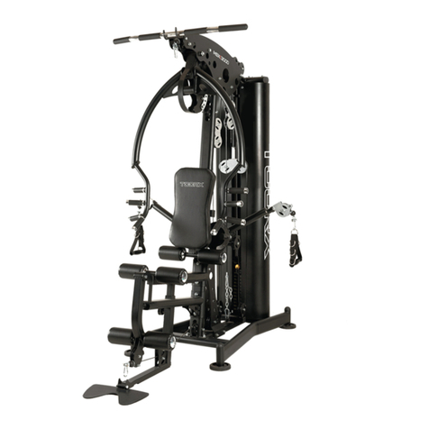
  9. TOORX MSX-300 User manual

TOORX MSX-300 User manual

Ed : Rev : Cod :
INSTRUCTION
01/23 GRLDTOORXMSX3000
STEP 1:
1. Insert two Guide Rods (14) into the Rear Stabilizer (2), using two Allen Bolts M10×25mm (104) and two
Washers M10 (109).
2. Attach the Base Frame(8) and Arc Brackets(28) to the Rear Stabilizer(2), using two Carriage Bolts
M10×100mm (91), two Washers M10 (109) and two Nylon Locknuts M10(113).
3. Attach the Support Frame(3) and U-shaped Brackets(30) to the Base Frame(8), using four Carriage Bolts
M10×60mm (94), four Washers M10 (109) and four Nylon Locknuts M10 (113).
4. Attach the Bracket 120×45mm (27) to the Base Frame(8), using two Carriage Bolts
M10×60mm (94),
Do not tighten the nuts and bolts except (104) and (91).
STEP 2:
1. Attach the Crossover Support Frame (15) to the Base Frame(8), using one Allen Bolts M10×100mm (96),
two Washers M10 (109) and one Nylon Locknut M10(113).
2. Attach the Cable Crossover Support(11) to the Crossover Support Frame (15), using the Bracket 120×45mm
(27), two Carriage Bolts M10×65mm (93), two Washers M10 (109) and two Nylon Locknuts M10(113).
3. Attach the Cable Crossover Support(11) and Arc Brackets(28) to the Support Frame(3), using two Carriage
Bolts M10×100mm (91), two Washers M10 (109) and two Nylon Locknuts M10 (113).
Do not tighten the nuts and bolts yet.
STEP 3:
1. Slide two weight cover brackets(33) onto Guide Rods (14), then attach them to the Rear Stabilizer (2),using
two Allen Bolts M10×25mm (104) and two Washers M10 (109).
2. Slide two Rubber Bumpers Ø65×25mm(64) onto Guide Rods (14).
3. Slide fourteen Weight Plates(41) onto Guide Rods (14), insert the Selector Rod (13) into the hole of the
Weight Plate (41).
4. Slide the Top Weight Plates(36) down two Guide Rods (14), then down the Selector Rod (13), insert the
Weight Select Pin(59) into hole of desired weight.
5. Attach the Seat Support Frame(5) to the Support Frame (3), using two Carriage Bolts M10×100mm (91), two
Washers M10 (109) and two Nylon Locknuts M10(113).
6. Attach the Seat Support Frame(5) and Bracket 120×45mm (27) to the Front Support Frame(1), using two
Carriage Bolts M10×70mm (92),two Washers M10 (109) and two Nylon Locknuts M10(113).
7. Attach the Support Frame(1) to the Base Frame (8), using two Washers M10 (109) and two Nylon Locknuts
M10(113).
Do not tighten the nuts and bolts except (104).
STEP 4:
1. Slide two weight cover brackets(33) onto Guide Rods (14).
2. Attach the Upper Frame(4) to the Support Frame(3), using one Arc Bracket(28), two Carriage Bolts
M10×100mm (91), two Washers M10(109) and two Nylon Locknuts M10 (113).
3. Attach the Upper Frame(4) to the top of Guide Rods (14), using two Allen Bolts M10×25mm (104) and two
Washers M10(109).
4. Attach the Front Leg Developer(7) to the Support Frame(1), using one Allen Bolt M10×80mm (97), two
Washers M10 (109) and one Nylon Locknut M10 (113).
5. Attach the Foot Plate(17) to the Base Frame(8),using one Foot Plate Tube (26).
Do not tighten the nuts and bolts yet.
STEP 5:
1. Attach the Front Press Base(12) to the Upper Frame (4), using one Ø16×172×M10 Axle(31),two Washers
Ø25× Ø10 (108) and two Nylon Nuts M10 (113).
2. Attach the Front Press Frame (6) to the Front Press Base(12), using one Ø16×198×M10 Axle(32), two
Washers Ø25× Ø10 (108), two Bushings Ø31ר25.7×8(70) and two Nylon Locknuts M10 (113).
3. Insert the Insert Pin (38-41) through the single hole on the Front Press Frame(6) and align to any one of the
holes on fan-type plate.
STEP 6:
1. Attach the Left Cable Crossover Arm(18) to the Cable Crossover Support(11), using one Nylon Nut M24
(112), insert the T Shaped Pin (37) onto the Left Cable Crossover Arm(18) to any one
of the holes on fan-type plate.
2. Attach the Right Cable Crossover Arm(19) to the Cable Crossover Support (11), using one Nylon Nut M24
(112), insert the T Shaped Pin (37) onto the Right Cable Crossover Arm(19) to any one of the holes on fan-type
plate.
3. Attach Two Cable Crossover Pulley Brackets(16) to the Left and Right Cable Crossover
Arm(18&19), using two Nylon Locknuts M24 (112).
Note: Install Nylon Nuts M24 (112), using one Special wrench 38-42#
STEP 7:
1. Attach the Backrest Pad (44) to the Backrest Frame (9), using two Allen bolts M8×40mm(105) and two
Washers M8 (110).
2. Insert the Backrest Frame (9) into the Support Frame (3), using one Lock Knob(60).
3. Attach Seat Pad (45) to the Seat Frame (10), using four Allen bolts M8×18mm(106) and four Washers M8
(110).
4. Insert the Seat Frame (10) into the Seat Support Frame (5), using one Lock Knob(60).
5. Attach the Arm Curl Pad (40) to the Arm Curl Frame (39), using two Allen bolts M8×18mm(106) and two
Washers M8 (110).
6. Insert the Arm Curl Frame (39) into the Front Support Frame(1), using one Lock Knob(60).
7. Insert two Foam Roll Tubes (25) into Front Support Frame(1) and the Front Leg Developer(7).
8. Slide four Foam Rolls (46) onto two Foam Roll Tubes (25), then tap four Foam Roll End Cap (67).
STEP 8:
Assembly of the Upper Cable (51)
a) With Upper Cable (51) in groove of Large Pulley(63), thread Upper Cable(51) through Upper Frame(4).
b) Install Large Pulley NO.1 (63) to Upper Frame (4), using one Allen Bolt M10×60mm (100), two Pulley Bushing
(68), two Washers M10 (109),and one Nylon Locknut M10 (113).
c) Install Large Pulley NO.2 (63) to Upper Frame (4), using one Allen Bolt M10×60mm (100), two Pulley Bushing
(68), two Washers M10 (109),and one Nylon Locknut M10 (113).
d) Install Large Pulley NO.3&5 (63) to Front Press Base (12), using two Allen Bolts M10×155mm (95), four
Washers M10 (109), and two Nylon Locknuts M10 (113).
e) Install Large Pulley NO.4 (63) to Support Frame (3), using one Allen Bolt M10×50mm (102), two Cable
Retainers (65), two Cable Retainer Bushings (66), two Washers M10 (109), and one Nylon Locknut M10 (113).
f) Install Large Pulley NO.6 (63) to Support Frame (3), using one Allen Bolt M10×60mm (100), two Pulley
Bushing (68), two Washers M10 (109),and one Nylon Locknut M10 (113).
g) Install Large Pulley NO.7 (63) to Support Frame (3), using one Allen Bolt M10×50mm (102), two Cable
Retainers (65), two Cable Retainer Bushings (66), two Washers M10 (109), and one Nylon Locknut M10 (113).
h) Install Large Pulley NO.8 (63) to Double Pulley Bracket (24), using one Allen Bolt M10×50mm (102), two
Cable Retainers (65), two Cable Retainer Bushings (66), two Washers M10 (109), and one Nylon Locknut M10
(113).
I ) Install Large Pulley NO.9 (63) to Upper Frame (4), using one Allen Bolt M10×60mm (100), two Pulley Bushing
(68), two Washers M10 (109), and one Nylon Locknut M10 (113).
j ) Install Large Pulley NO.10 (63) to two Adjustable Pulley Brackets (29), using one Allen Bolt M10×50mm (102),
two Cable Retainers (65), two Cable Retainer Bushings (66), two Washers M10 (109), and one Nylon Locknut
M10 (113).
k) Install Large Pulley NO.11 (63) to Upper Frame (4), using one Allen Bolt M10×60mm (100), two Pulley
Bushing (68), two Washers M10 (109),and one Nylon Locknut M10 (113).
L) Attach the bolt end of Upper Cable (51) to Selector Rod (13).
STEP 9:
Assembly of the Shoulder Cable (52)
a) With Shoulder Cable (52) in groove of Large Pulley(63), thread Shoulder Cable(52) through the Support
Frame(3).
b) Install Large Pulley NO.12 (63) to Support Frame (3), using one Allen Bolt M10×60mm (100), two Pulley
Bushing (68), two Washers M10 (109), and one Nylon Locknut M10(113).
c) Install Large Pulley NO.13 (63) to Support Frame (3), using one Allen Bolt M10×50mm (102), two Cable
Retainers (65), two Cable Retainer Bushings (66), two Washers M10 (109), and one Nylon Locknut M10 (113).
d) Install Large Pulley NO.14 (63) to the Double Pulley Bracket (24), using one Allen Bolt M10× 50mm (102),
two Cable Retainers (65), two Cable Retainer Bushings (66), two Washers M10 (109), and one Nylon Locknut
M10 (113).

e) Attach the Single Pulley Bracket (23) to the end of Shoulder Cable (52), using one Allen Bolt
M10×25mm (104), two Washers M10 (109), and one Nylon Locknut M10 (113).
STEP 10:
Assembly of the Crossover Cable (53)
a) Run the end of Crossover Cable (53) through Left & Right Cable Crossover Arms(18&19), and Cable
Crossover Support (11).
b) Attach the Cable U (55) to the ball end of Crossover Cable (53).
c) Attach one Carabiner (58) to Cable U (55), using one Allen bolt M10×35mm (103), two Washers M10 (109),
and one Nylon Locknut M10 (113).
d) Install Middle Pulley NO.15 (62) to Cable Crossover Pulley Bracket (16), using one Allen bolt
M10×50mm(102), two Washers M10 (109), and one Nylon Locknut M10 (113).
e) Install Small Pulley NO.16 (61) to the Left Cable Crossover Arm (18), using one Allen bolt M10×50mm (102),
two Washers M10 (109), and one Nylon Locknut M10 (113).
f ) Install Middle Pulley NO.17 (62) to the Cable Crossover Support (11), using one Allen bolt M10×50mm (102),
two Washers M10 (109), and one Nylon Locknut M10 (113).
g) Install Large Pulley NO.18 (63) to the Base Frame (8), using one Allen Bolt M10×50mm (102), two Cable
Retainers (65), two Cable Retainer Bushings (66), two Washers M10 (109), and one Nylon Locknut M10 (113).
h) Install Large Pulley NO.19 (63) to the Single Pulley Bracket (23), using one Allen Bolt M10×50mm (102),
two Cable Retainers (65), two Cable Retainer Bushings (66), two Washers M10 (109), and one
Nylon Locknut M10 (113).

i ) Install Large Pulley NO.20 (63) to the Base Frame (8),using one Allen Bolt M10×50mm (102), two Cable
Retainers (65), two Cable Retainer Bushings (66), two Washers M10 (109), and one Nylon Locknut M10
(113).
j ) Install Middle Pulley NO.21 (62) to the Cable Crossover Support (11), using one Allen bolt M10×50mm
(102), two Washers M10 (109), and one Nylon Locknut M10 (113).
k) Install Small Pulley NO.22 (61) to the Right Cable Crossover Arm (19), using one Allen bolt M10×50mm
(102),two Washers M10 (109), and one Nylon Locknut M10 (113).
I ) Install Middle Pulley NO.23 (62) to Cable Crossover Pulley Bracket (16), using one Allen bolt M10×50mm
(102), two Washers M10 (109), and one Nylon Locknut M10 (113).
m) Attach two Cable U (55) to the ball end of Crossover Cable (53).
n ) Attach two Carabiners (58) to Cable U (55), using two Allen bolts M10×35mm (103), four Washers M10
(109),and two Nylon Locknuts M10 (113).
STEP 11:
Assembly of the Lower Cable (54)
a) Position the Lower Cable (54) in the groove of Large Pulley(63) through Front Leg Developer(7).
b) Install Large Pulley NO.24 (63) to Front Leg Developer (7), using one Allen Bolt M10×65mm (99), two
Washers M10 (109), and one Nylon Locknut M10 (113).
c) Install Large Pulley NO.25 (63) to Front Support Frame (1), using one Allen Bolt M10×70mm (98), two
Washers M10 (109), and one Nylon Locknut M10 (113).
d) Install Large Pulley NO.26 (63) to Base Frame(8), using one Allen Bolt M10×50mm(102), two Cable
Retainers(65), two Cable Retainer Bushings(66), two Washers M10(109), and one Nylon Locknut M10 (113).
e) Install Large Pulley NO.27 (63) to Adjustable Pulley Brackets (29),using one Allen Bolt M10×50mm (102),two
Cable Retainers (65), two Cable Retainer Bushings (66), two Washers M10 (109), and one Nylon Locknut M10
(113).
f) Install Large Pulley NO.28 (63) to Base Frame (8), using one Allen Bolt M10×50mm (102), one Cable Retainer
(65), one Cable Retainer Bushing (66), two Washers M10 (109), and one Nylon Locknut M10 (113).
g) Attach one Cable U (55) to the ball end of Lower Cable (54), using one Allen bolt M10×35mm (103), two
Washers M10 (109), and one Nylon Locknut M10 (113).
STEP 12:
a) Attach Lat Bar (20) to the other end of Upper Cable (51), using two Carabiners (58) and one Chain
7-Link (57).
b) Attach Lower Bar (21) or Ankle Strap (48) to the other end of Lower Cable (54), using two Carabiners(58)
and one Chain 15-Link (56).
c) Attach AB Strap (50) to the other end of Shoulder Cable (52), using one Carabiner(58) .
d) Attach two Strap Handles (49) to both ends of Crossover Cable (53), using two Carabiners(58) .
STEP 13:
a) Attach the two weight cover brackets (33) to the Upper Frame(4) , using two Allen Bolts M10×45mm (101),
four Washers M10 (109) and two Nylon Locknuts M10 (113).
b) Attach the Weight Covers (47) to the weight cover brackets (33),using twelve Allen Bolts M10×16mm(107)
and twelve Washers M10 (109).
STEP 14:
a) Attach the Left Frame (34) and the Right Frame (35) to the Support Frame (3) , using two Carriage Bolts
M10×60mm (94), two Washers M10 (109) and two Nylon Locknuts M10 (113).
b) Attach the Left Frame (34) and the Right Frame (35) to the Rear Stabilizer (2) , using two Allen Bolts
M10×100mm (96), four Washers M10 (109) and two Nylon Locknuts M10 (113).
GARLANDO SPA
Via Regione Piemonte, 32 - Zona Industriale D1
15068 - Pozzolo Formigaro (AL) - Italy
www.toorx.it - info@toorx.it

Other manuals for MSX-300

1

Other TOORX Fitness Equipment manuals

TOORX CSX70 User manual

TOORX

TOORX CSX70 User manual

TOORX ERX900 User manual

TOORX

TOORX ERX900 User manual

TOORX MSX 60 User manual

TOORX

TOORX MSX 60 User manual

TOORX BRXOffice Compact User manual

TOORX

TOORX BRXOffice Compact User manual

TOORX BRX R300 ERGO User manual

TOORX

TOORX BRX R300 ERGO User manual

TOORX WLX70 User manual

TOORX

TOORX WLX70 User manual

TOORX Rower Force User manual

TOORX

TOORX Rower Force User manual

TOORX BRX RECUMBENT COMPACT User manual

TOORX

TOORX BRX RECUMBENT COMPACT User manual

TOORX WBX-250 User manual

TOORX

TOORX WBX-250 User manual

TOORX WBX40 User manual

TOORX

TOORX WBX40 User manual

TOORX WLX80 User manual

TOORX

TOORX WLX80 User manual

TOORX MSX 60 User manual

TOORX

TOORX MSX 60 User manual

TOORX CLX-9000 User manual

TOORX

TOORX CLX-9000 User manual

TOORX WLX2800 User manual

TOORX

TOORX WLX2800 User manual

TOORX ERX90 User manual

TOORX

TOORX ERX90 User manual

TOORX ERX70 User manual

TOORX

TOORX ERX70 User manual

TOORX WBX85 User manual

TOORX

TOORX WBX85 User manual

TOORX WBX-2400 User manual

TOORX

TOORX WBX-2400 User manual

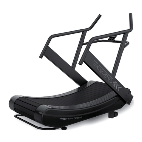
TOORX TRX Speed Cross User manual

TOORX

TOORX TRX Speed Cross User manual

TOORX BRX R9500 User manual

TOORX

TOORX BRX R9500 User manual

TOORX Chrono Line RWX500 User manual

TOORX

TOORX Chrono Line RWX500 User manual

TOORX SRX3500 User manual

TOORX

TOORX SRX3500 User manual

TOORX FWX5600 User manual

TOORX

TOORX FWX5600 User manual

TOORX TRX 9500 User manual

TOORX

TOORX TRX 9500 User manual

Popular Fitness Equipment manuals by other brands

Revitive Arthritis-Knee user manual

Revitive

Revitive Arthritis-Knee user manual

Domyos BM100 operating instructions

Domyos

Domyos BM100 operating instructions

Movement EDGE PUXADA ALTA Assembly manual

Movement

Movement EDGE PUXADA ALTA Assembly manual

Lifeline LLUWB-BLK owner's manual

Lifeline

Lifeline LLUWB-BLK owner's manual

Precor CW-816 Assembly guide

Precor

Precor CW-816 Assembly guide

Balanced Body Precision Rotator Discs manual

Balanced Body

Balanced Body Precision Rotator Discs manual

G-FITNESS AIR ROWER user manual

G-FITNESS

G-FITNESS AIR ROWER user manual

CAPITAL SPORTS Dominate Edition 10028796 manual

CAPITAL SPORTS

CAPITAL SPORTS Dominate Edition 10028796 manual

Martin System TT4FK user guide

Martin System

Martin System TT4FK user guide

CIRCLE FITNESS E7 owner's manual

CIRCLE FITNESS

CIRCLE FITNESS E7 owner's manual

G-FITNESS TZ-6017 user manual

G-FITNESS

G-FITNESS TZ-6017 user manual

Accelerated Care Plus OMNISTIM FX2 CYCLE/WALK user manual

Accelerated Care Plus

Accelerated Care Plus OMNISTIM FX2 CYCLE/WALK user manual

pedalo 20230165 manual

pedalo

pedalo 20230165 manual

Saebo SaeboStim Pro Instructions for use

Saebo

Saebo SaeboStim Pro Instructions for use

Performance HyperVibe User instructions

Performance

Performance HyperVibe User instructions

Scalamobil S27 Operator's manual

Scalamobil

Scalamobil S27 Operator's manual

Precor Experience Series Service manual

Precor

Precor Experience Series Service manual

FYTTER RedMIUM BENCH BE-T6R manual

FYTTER

FYTTER RedMIUM BENCH BE-T6R manual

manuals.online logo
manuals.online logoBrands
  • About & Mission
  • Contact us
  • Privacy Policy
  • Terms and Conditions

Copyright 2025 Manuals.Online. All Rights Reserved.