TOORX TRX 9000 EVO TFT User manual

Ed : Rev : Cod :
INSTRUCTION
08/22 TOXPRFTRX9000ET00

2
18. The equipment is suitable for commercial use. Maximum weight of user :180kg
Warning:Violation of the above safety regulations will cause personal injury and equipment damage.
User’s guide
Hardware and tool
(A8)M10×20
halfround hex
socket bolt
12pcs
(C2)φ10
flat washer
22pcs
(A4)M10×25
hex bolt
8pcs
(B1)M10
nylon locking
nut
2pcs
(C5)φ10
spring washer
8pcs
(A9)ST4×30
cross pan head
tapping screw
2pcs
(A17)ST4×16
cross pan head
tapping screw
6pcs
(D1)S=17
wrench
1pc
(D3) wrench
(S=6)
1pc
(D2)screwdriver
1pc
(D4)S=8
wrench
1pc
(D5)lubricant
bottle
1pc

3
Exploded drawing

4
Parts list
No.
Description
Qty
No.
Description
Qty
1
Base frame
1
41
Signal wire A
2
2
Switch base frame
1
42
Signal wire B
2
3
Incline frame
1
43
Signal wire C
2
4
Left upright tube
1
44
Signal wire D
2
5
Right upright tube
1
6
Handlebar and controlling
panel
1
7
Display screen
1
A1
Bolt M8X55
1
A2
Bolt M10X95
1
9
Front roller
1
A3
Bolt M10X55
1
10
Rear roller
1
A4
Bolt M10X25
8
11
10 V belt
1
A5
Bolt M10X75
4
12
Running board
1
A6
Bolt M10X165
2
13
Running board cushion
8
A7
Half-round bolt M8X20
2
14
Rubber mat
8
A8
Half-round bolt M10X20
10
15
Running belt
1
A9
Crosshead tapping bolt ST4X30
2
16
Universal wheel mat
2
A10
Half-round bolt M8X45
6
17
Left side rail
1
A11
Half-round bolt M10X60
2
18
Right side rail
1
A12
Round bolt M10X90
2
19
Non-slip colloidal particles
84
A13
Crosshead screw M8X70
8
20
Position nut
6
A14
Crosshead screw M3X8
2
21
Shock absorption mat
4
A15
Crosshead screw M5X40
2
22
Baffle plate
1
A16
Crosshead screw M5X20
2
23
Motor top cover
1
A17
Crosshead tapping screw
ST4X16
27
24
Motor left cover
1
25
Motor right cover
1
B1
Hexagon Nut M8
8
26
Motor front cover
1
B2
Nylon lock nut M5
2
27
Left end cap
1
B3
Nylon lock nut M8
8
28
Right end cap
1
B4
Nylon lock nut M10
14
29
Middle end cap
1
C1
Flat washerφ8
8
30
Rear roller cap
2
C2
Flat washerφ10
24
31
Motor (AC)
1
C3
Big flat washerφ10
4
32
Incline motor
1
C4
Flat washerφ5
2
33
Converter
1
C5
Spring washerφ10
10
34
Emergency stop switch
1
C6
Spring washerφ5
2
35
Power switch
1
C7
Nylon Washerφ10
4
36
socket
1
D1
Wrench
1
37
wheel
2
D2
Screwdriver
1
38
Cushion
2
D3
Wrench (s=6)
1

5
39
Nut cap
4
D4
Wrench (s=8)
1
40
Safety key/emergency button
set
1
D5
Lubricant bottle
1
Note: Pls refer to the actual parts if there is difference with the ones in the list.
Installation instruction
WARNING: Don’t insert the power wire until the treadmill was fully installed.
Tips:
*To eliminate installation errors, do not tighten all the bolts in each step. Tighten all the bolts after the
installation is complete.
*One treadmill is packed in 2 cartons, #1 is for main frame, # 2 is for the handle bar and central controling
panel.
1. Unpack and lift out of the frame
The frame is fixed with a bracket and
X,Before leaving the factory, the rack is fixed
with a bracket and X, Unscrew the X (there
are four in total )mounted on the frame with a
wrench. Then lift the frame out. As shown in
Figure 1
2.Installation of left upright tube
2.1 Install Left upright tube (4) to base frame
(1) by four sets of bolt M10X25 (A4), Flat
washersφ10 (C2) by side. (Attention: to align
screw hole with the upper surface). Make sure
the bolts to connect left upright tube and base
frame. (See Figure 2)
2.2 In upper inner side, using one piece of
Flat washer φ10 (C2) and one piece of Nylon
lock nut M10 (B4) to tighten. In upper outer
side, using Bolt M10X165 (A6) that was
assembled on frame to tighten.(Attention: bolt head position is the front underside. See Figure 2-1)
3.Installation of right upright tube

6
3.1 Connect the Signal wire from right upright
tube to corresponding wires from frame.
3.2 Install the Right upright tube (5) to base
frame (1) using four sets of bolt M10X25 (A4),
Flat washersφ10 (C2) by side. (Attention: to
align screw hole with the upper surface).
Make sure the bolts to connect right upright
tube and base frame. (See Figure 3)
3.3 In upper inner side, using one piece of Flat
washer φ10 (C2) and one piece of Nylon lock
nut M10 (B4) to tighten. In upper outer side, using Bolt M10X165 (A6) that was assembled on frame to
tighten.(Attention: bolt head position is the front underside. See Figure 3-1)
4.Installation of handlebar and
conlloring panel
4.1Connect the Signal wire from Right upright
tube to corresponding wires from Handlebar.
4.2 Install handlebar and controlling panel
set(6) to the Left/Right upright tube (4/5).
4.3 Connect handlebar and controlling panel
(6) to the Left/Right upright tube (4/5) by 8
sets of Half-round bolt M10X20(A8),Spring
washerφ10(C5),Flat washerφ10(C2).
(Attention: To align screw hole)(See Figure 4)
5.Installation of display scrern
5.1 Connect the signal wire from display
screen to corresponding wire from controlling
panel. Crowding the extra wire into the panel.
5.2 Connect the display screen (7) to
handlebar and controlling panel (6) by 4 sets
of Half-round bolt M10X20(A8),Flat
washersφ10(C2).(Attention: To align screw
hole)(See Figure 5)

7
6. Installation of motor left/right
cover
6.1 Tighten all the installation bolts
6.2 Install motor left cover (24) to top motor
cover (23) of base frame (1) by 1pc of
Crosshead self-lock bolt ST4X30 (A9) in front
and 3pcs Crosshead self-lock bolt ST4X16
(A17) to tighten.
6.3 Install motor right cover(25) to top
cover(23) of base frame (1) by 1pc of
Crosshead self-lock bolt ST4X30 (A9) in front
and 3pcs Crosshead self-lock bolt
ST4X16(A17) to tighten.(See Figure 6)
WARNING: Improper connection of the grounding conductor may cause electric shock.
If you’re not sure whether the device is properly grounded, please turn to a professional
electrician or repairman to inspect. Do not modify the plug supplied with the product, if the plug
does not match the socket, you should turn to a professional electrician to install a proper socket.
Adjustment instruction
1.Before connectting power, service or professional personel should check whether voltage
is appropriated, and whether the ground wire of three-core plug is wellconnected. Pull the
running belt by hand, check whether the rotation is flexible, there is no abnormal sound.
2. Connect power, press Start key, the treadmill starts to run in low speed,observe whether
belt and computer are run normally.
3. Press the speed up and down key to observe the rotation and display of the treadmill. If
the belt deviated, stop the treadmill and adjust the running belt according to the requirements
of "maintenance".
4.Press emergency stop key or pull out safety key,the treadmill will stop immediately. Re-
inset the emergency stop key to reset or insert safety key, can restart treadmill. (As below
figure)
5.Press Stop key, the treadmill stop running, then turn off the power when the incline returns
to zero .
Treadmill can be put into use after all the installation adjustment is completed.

8
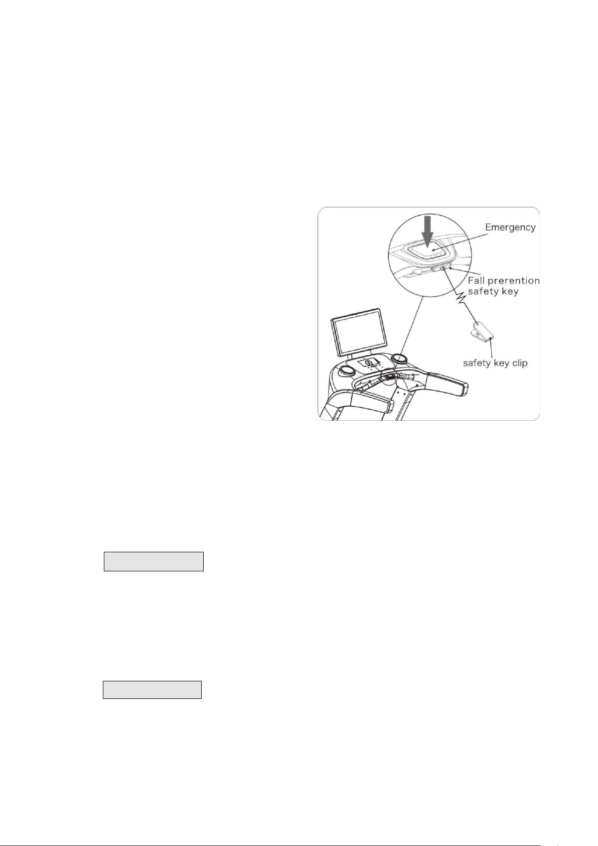
1.1.Two feet stand on two side of belt, put the other side clip from safety key to clip to
clothes. (see the figure)
2.Press Start key, the treadmill will start running at lowest speed. You can step on the belt and walk
slowly.
3.Press speed+ key, the speed of running belt will gradually increase, you can see the speed
value from computer, start to run at low speed for 2-3 minutes, then increase the speed to
your target, you can release the handlebar after after run is suitable, you can let go handrail
to run after adaptation.
4.When stopping running, you should slow
down gradually and run for 2-3 minutes at a low
speed, so that the heart and breathing slowly
return to normal.
5.After running, you can reduce speed to the
minimum, and then press the start/stop button
to stop the treadmill.
6.If running at high speed, it is too late to slow
down, or even lose balance, you can press the
emergency stop button, and the treadmill can
stop running immediately. The stopping
distance depends on the inertial weight.
7.Please fully master the use of emergency stop
button and safety key.
8.If the emergency stop button and safety key fail or are damaged, they must be
maintained or replaced by professionals in time. (They are earsily worn parts)
9.Noise under load is higher than that without load.
WARNING: Frequent use of incline operation (more than 5 times in a row) may render the incline
ineffective. It's not a malfunction. It is a kind of automatic protection of inclinemotor, the function will be restored automatically
after 1 hour stop using.
TFT instruction
WARNING: To reduce the possibility of electric shock, keep the console dry. To prevent liquid from spilling onto
the console, only sealed water bottles can be placed on the water bottle holder.
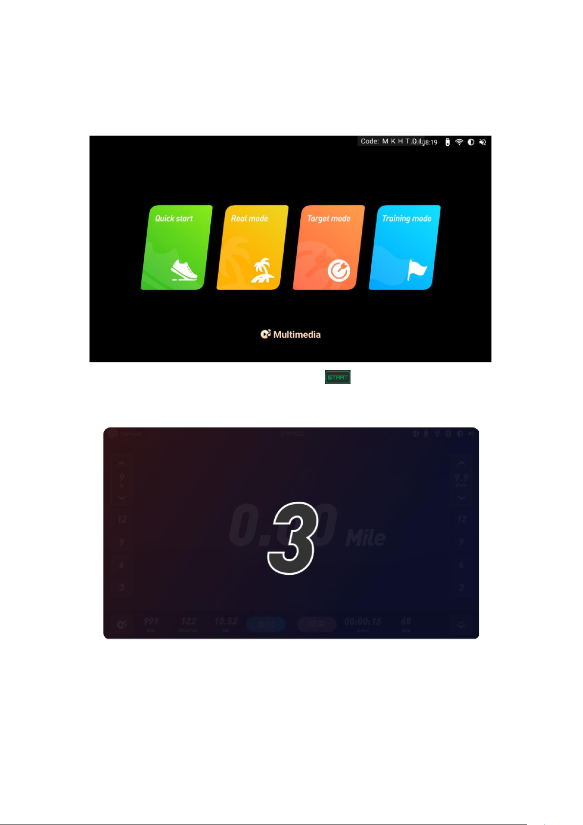
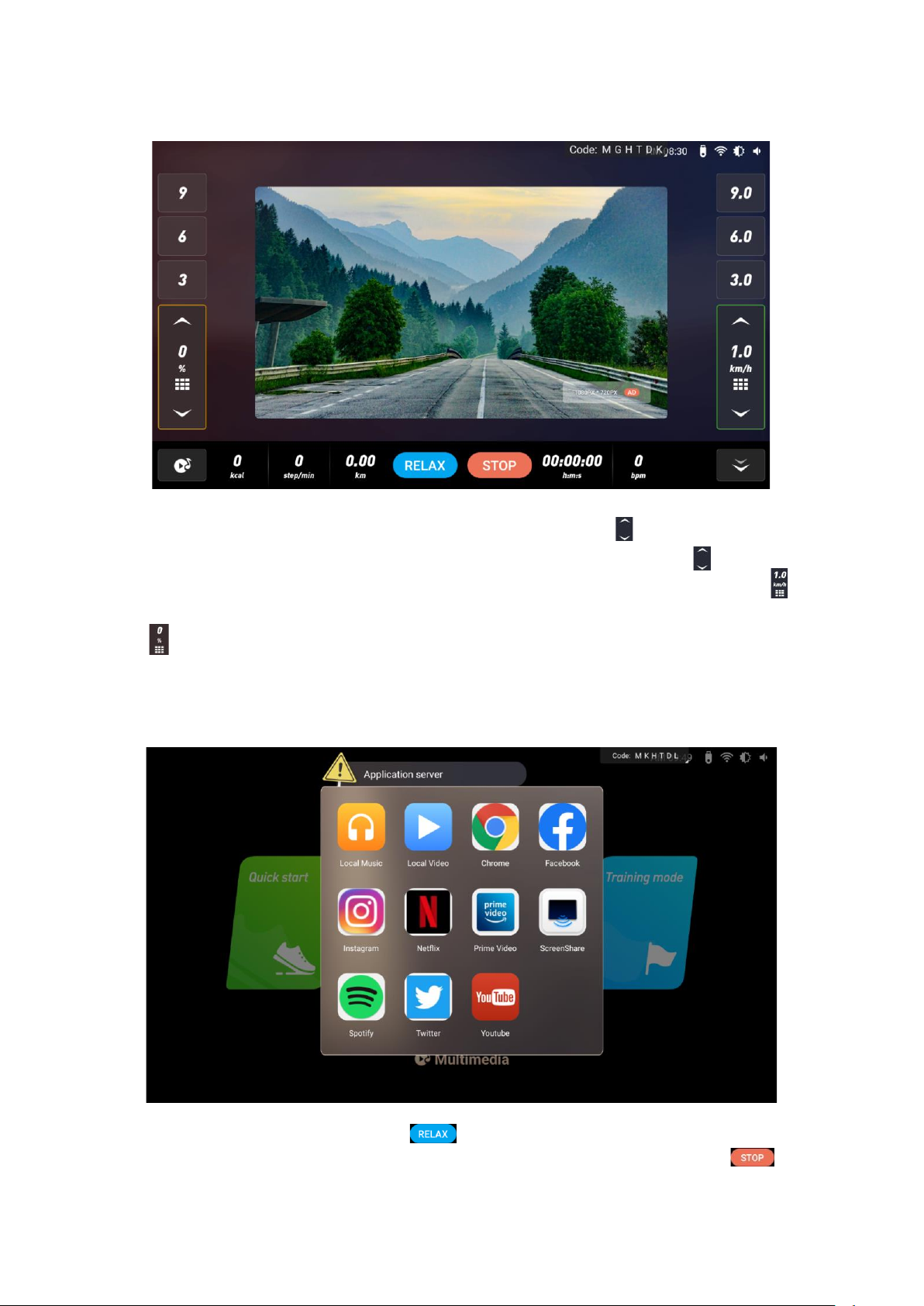
1. Quick start
The treadmill adopts 21.5 inch high resolution touch screen to display the data and
sports state during exercise, and installs multimedia APP application and running training

9
mode to make sports entertainment more rich and interesting. Power on, turn on the main
power switch of the treadmill, install the safety switch key then enter into the main menu
as shown below
Click the "Quick Start" on the screen or the " " button on the console to start
quickly. The treadmill will directly start the countdown and enter running mode as shown
below:

10
Main interface in running state is shown as below:
After starting the treadmill, press the speed adjustment button (+ -/ ) on the controlling panel
or color screen to adjust your running speed. Press the incline adjustment key (+ -/ ) to adjust the
comfortable running incline; Press the speed direct selection key (3-6-9) or fast selection key ( ) on
the screen to quickly select the speed; Press incline direct selection button (3-6-9) or quick selection
button ( ) on the screen to quickly select the incline. For your safety, try not to operate other functions
on the screen when running. If you want to operate the media APP function , please do it when it is
lower than 3KM/H or in the shutdown state. Click the "multimedia" icon on the interface to enter the
APP interface, as shown in the picture below, you can browse Twitter, Facebook... and so on.
When the speed is > 1KM/H, click the " " , the speed will be reduced to a comfortable
state and the incline to the initial state value. When you want to stop running, press the " " on

11
the home page or the" "button on the controlling panel, and a window that is about to end running
will pop up on the home page to provide" Keep onrunning "or" Stop ", as shown below:
If you need to stop running in an emergency, please pull out the safety key or press the emergency
stop button to stop the treadmill. Then it will be shown as belwo:
After inserting the safety key, it will switch to the main menu page, as shown below:

12
In the standby mode, you can choose the Quick start mode, Real mode, Target mode, Training
mode and other sports programs to train, and you can also choose Multimedia for other operations.
2. Controlling panel instruction
2.1 Mechanical button operation
Start:after power on, press “START”,the treadmill starts running.
Stop/pause: press this button when running, the treadmill will puase, and press again
to stop running. After the pause, press the start button and the treadmill will return to the running state
before the pause.
Speed adjustment:when the treadmill is running, press this key to adjust the speed, keep pressing
will lead to fast adjustment.
Incline adjustment: when the treadmill is running, press this key to adjust the incline, keep pressing
will lead to fast adjustment.
Emergency stop button/Safety key: it is a safety device to prevent slipping or forced shutdown
in emergency. When using the treadmill, you need to insert the safety key inward (after
inserting the safety key, the emergency stop button will automatically reset and spring up), press the
emergency stop button or pull out the safety key side of the treadmill to stop running.
Wireless charging: when the treadmill is powered on, if the mobile phone has wireless
Speed up
Incline up
Wireless charging
Incline down
Speed down
Start
Stop/pause

13
charging function, put the mobile phone in the charging slot, and the wireless charging can play.
2.2 Buttons in touch screen
2.2.1 Quick start: when the treadmill is powered on, click this button then the
Treadmill starts to run.
2.2.2 Real mode:click this button to enter the real scene selection interface.
2.2.3 Target mode:click this button to enter the target selection interface.
2.2.4 Training mode: click this button to enter the traning selection interface.
2.2.5 Multimedie: click this button to view different applications.
2.2.6 :click this button to return to the previous menu.
2.2.7 :click this button to switch to the full screen.
2.2.8 : click this button to switch to the initial interface.
2.2.9 Stop: clip this button to stop running the treadmill.
2.2.10 Cool down: Click this button to reduce the treadmill speed/incline to the initial state of
comfortable exercise.
2.2.11 Speed/Incline up: click this button to increase running speed / incline.
2.2.12 Speed/Incline down:click this button to decrease running speed/incline.
2.2.13 Quick speed selection: click this button to enter quick speed selection.
2.2.14 Quick incline selection:click this button to enter quick incline selection.

14
3. Display screen instruction
4. Instruction of running programs and setting operation
4.1 Treadmill operation instruction
Switch on the power, the treadmill enters the standby state, press “START”, the treadmill starts to
run, you can choose the speed or incline button to adjust, press “STOP” to stop running. In the
standby state, if there is no signal input for a long time, the treadmill enters the black screen of
shutdown standby state. Press any physical mechanical button to light up the screen and return to the
standby. Before starting the treadmill, you can choose system settings or training mode.
4.2 Status bar and shortcut Settings
Under the power-on state, you can set the system. Through the status bar and shortcut setting
area in the upper right corner of the home page, you can open the shortcut setting menu, adjust the
treadmill volume, screen brightness and set bluetooth. Advanced Settings are the management menu
of treadmill, it is non-user menu, but only for equipment maintenance personnel. As shown below:
21.5” Touch sreen
Bottle holder
Bottle holder
Controlling panel
Wireless charging
Emergency stop
Safety key
Right handpulse detection
metal plate
Left handpulse detection
metal plate
Audio input
USB

15
4.3 Real mode
Click "REAL MODE”on the screen, the treadmill enters the real scene selection interface with six
built-in scenes, as shown below:
Users can choose their favorite real scene, click to enter the scene running. For example: the user
chooses "Beach" real scene, beach scene running will be started. As shown below:

16
Press the speed adjustment button (+ -/ ) on the controlling panel or screen to adjust the speed of
running. Press the speed direct selection key (3-6-9) or fast selection key ( ) on the screen to
quickly select the speed. Note: In the real running mode, there is no need to adjust the incline. The
system will automatically set it according to the terrain changes in the real scene.
4.4 Target mode
Click “TARGET MODE” to enter the target selection interface, which has three types, as shown
below:
4.4.1 Distance:Built-in 2/4/6/8/ Mini marathon/half marathon/full marathon/custom options. The
distance will gradually decrease as you run, then come to end when it drop to 0.
Users can select their target distance and click to enter the running interface. For example, users
can select a "4km" to start . As shown below:
Distance

17
Cutom mode:Press the button to enter the setting interface. After setting, click "Start running"
to run. As shown below:
4.4.2 Time:Built-in 15/30/45/60/90/120/150/custom options. The setting time will gradually decrease
as you run, then come to end when it reaches 0.
Users can select their target time and click to enter the running interface. For example, the user
selects the "15 minute" to start. As shown below:

18
Custom mode:Press "Custom" to enter the setting interface. After setting, click "Start running"
to run. As shown below:
4.4.3 Calorie:Built-in for 100/200/300/400/500/1000/1500 / custom options. The setting calories will
gradually decrease as you run, then come to end when it reaches 0.
Users can select their target calorie and click to enter the running interface. For example, the user
selects the "100" to start. As shown below:

19
Custom mode:Press "Custom" to enter the setting interface. After setting, click "Start running"
to run. As shown below:
4.5 Training mode
Click “Training mode” to enter the selection interface, as shown below:

20
4.5.1 In the training mode, the system provides a variety of preset training plans of Relax, Cardio,
Fat burning and Endurance for different running styles to help train stretching. Different running modes
have different incline and paces, so users can concentrate on running without worrying about various
Settings.
Users can select the training mode and click to enter the running interface. For example, when users
select "Relex", they can start running in this mode. As shown below:
4.5.2 Custom mode:If the preset training mode cannot meet users’ requirements, they can
customize the training mode, including: running duration,incline and speed of each running stage. You
can press and drag any rectangular bar to set different incline changes and different pace parameters in
different time periods. After setting, click “START” to run, as shown below:
Incline
Table of contents
Other TOORX Fitness Equipment manuals

TOORX
TOORX WBX-2400 User manual

TOORX
TOORX WBX40 User manual

TOORX
TOORX CLX-9000 User manual

TOORX
TOORX BRXOffice Compact User manual

TOORX
TOORX Professional Line WBX4000 User manual

TOORX
TOORX LDX 3000 User manual

TOORX
TOORX Rower Force User manual

TOORX
TOORX ERX70 User manual

TOORX
TOORX WLX80 User manual

TOORX
TOORX BRX RECUMBENT COMPACT User manual
Popular Fitness Equipment manuals by other brands

DAY 1 Fitness
DAY 1 Fitness BODY BAR MANUAL & EXERCISE GUIDE

KMART
KMART 43035991 manual

Precor
Precor Commercial Adaptive Motion Trainer C100i Service manual

HOMCOM
HOMCOM A90-256 Assembly & instruction manual

Element 26
Element 26 Self-Locking Weight Lifting Belt Instructional manual

Keys Fitness
Keys Fitness Power System KPS-BTM owner's manual