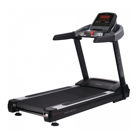
TOORX TRX GRAND CRUISER User manual

Ed : 03/17 Rev : 00
INSTRUCTION


3
ASSEMBLY
PACK
CHECK
LIST
#
97
. M6 (66 × 86)
L Allen Wrench (1pc)
ASSEMBLY PACK CHECK LIST
#
9
6
.
Combination M5 Allen Wrench &
Phillips Head Screw Driver (1pc)
#
147
.
5/16" × 15m/m
Button Head Socket Bolt (8pcs)
#
9
5
.
M5 × 10m/m
Phillips Head Screw (2pcs)
#
148
.
Ø8 × 1.5T
Split Washer (4pcs)
#
8
8
.
5 × 16m/m
Tapping Screw (4pcs)
#33. Safety Key (1pc) #58. Lubricant (1pc)
#
94
.
Ø5/16" × 19 × 1.5T
Curved Washer (2pcs)
#
1
32
.
M5
Speed Nut Clip (4pcs)
#
9
0
.
3/8" × 3/4"
Button Head Socket Bolt (4pcs)

4
ASSEMBLY
DRAWING
Step1.
Take out the treadmill from the carton and lay it aside on the smooth ground.
Step 2.
Guide Frame Base Covers (R , L) (42 , 43) go through Uprights (R , L), (4 , 5).
Connect the Computer Cable (Lower) (39) and Computer Cable (Middle)
(38).
39
38
42
43
4
5
Step3.
Insert Right and Left Uprights (4) and (5) into the Frame Base (2) with 4pcs of Speed Nut Clips
(132) and use Combination M5 Allen Wrench & Phillips Head Screw Drive (96) to tighten 8
pcs of 5/16" × 15m/m Button Head Socket Bolts (93) and 2pcs of Ø5/16" × 19 × 1.5T Curved
Washers (94).
94
93
93
94
93 93
5
4
96
132
132
132
132

5
ASSEMBLY
DRAWING
Step 4.
Use Combination M5 Allen Wrench & Phillips Head Screw Drive (96) to tighten four 5 ×
16m/m Tapping Screws (88) and two M5 × 10m/m Phillips Head Screws (95) to secure right
and left Frame Base Covers (42 , 43) on the mainframe.
88
95
88
88
88
95
43
42
96
Step5.
Connect the Computer Cable (Middle)(38) and Computer Cable (Upper)(37).
Connect the Speed/Hand Pulse Complex W/Cable (127) and Speed/Hand Pulse Complex
W/Cable (53).
Connect the Incline/Hand Pulse Complex W/Cable (128) and Incline/Hand Pulse Complex
W/Cable (54).
If there is HR receiver, connect Connecting Cable (Upper) (169) and Connecting Cable
(Lower) (170)
38
37
127
128
54
53
169
170

6
ASSEMBLY
DRAWING
Step6.
Use four 5/16" × 3/4" Button Head Socket Bolts (90) and four Ø8 × 1.5T Split Washers (148)
to secure the console assembly.
.
148
90
148
90
NOTE: Please Tighten All Screws After All Components Assembly Complete.


8
FUNCTIONS
Button Function:
“Start” key :Press this key, machine begins to run at the speed of 1.0 KPH / 0.6 MPH.
“Stop” key :Press this key, the walking belt will gradually slow down to stop.
“ENTER” key :When press this key, time, distance and calorie can be changed. Press “ FAST ”
or “ SLOW “, time, distance and calorie can be set. Then press “ START ” , the
machine runs at the speed of 1.0 KPH / 0.6 MPH, the set figures will be counted
down. When the figures turn to 0, machine stops.
“PROGRAM”KEY:Press this button to choose training mode. There are four modes:
MANUAL, RANDOM PROGRAM, USER and HRC (Heart Rate
Control).
“Speed” key:Press this key Speed " FAST " or "SLOW ", it can adjust the running speed of
the treadmill.
“Incline” key :Press this key Inclive " UP "or "DOWN ", it can adjust the incline of the
treadmill.
“Speed shortcut key” key:Press these keys, 2 , 4 , 6 , 8 , 10 it can be chosen directly which
speed you want. The highest speed is 16.0 KPH / 10.0 MPH.
“Incline shortcut key” key:Press these keys, incline 2 , 4 , 6 , 8 , 10 it can be chosen directly
which incline you want. The highest incline is level 12.
“FAN” key:This function is optional. Press this button to the fan on/off.
“Safety” key :key Under emergent situation, pull safety key, machine stops immediately.
Getting Started
Power the treadmill on by plugging it into an appropriate wall outlet, then turn on the power switch
located at the front of the treadmill below the motor shield. Ensure that the safety key is installed,
as the treadmill will not power on without it. When the power is turned on, all the lights on the
display will light for a short time.

9
FUNCTIONS
Speedy Start (P0MANUAL mode)
Press START button to speedily start the treadmill after turning on the power and putting on the
safety key. Both speed and incline will be at the lowest value. The user has to adjust them to the
desire levels manually.
There are two modes in using the MANUAL mode. One is the speedy start as described above to
use the preset parameters and accumulate the counts. The other is the count-down mode as
procedures below.
A. Use PROMGGRAM button to choose PO MANUAL then press ENTER to set
parameters. First is setting weigh. Use FAST/SLOW buttons to adjust the weigh and press
ENTER for next setting.
B. Now the AGE will be displayed. Use FAST/SLOW buttons to select the correct value
then press ENTER for next setting.
C. Choose one of count-down factors TIME, DISTANCE, CALORIES and use ENTER to
confirm then press ENTER to set the value.
D. Now the selected factor and the value will be displayed. Use FAST/SLOW buttons to
select the proper value and press START to start the treadmill and finish the setting.
E. You can press STOP button to return to the previous step or START to start the treadmill.
RANDOM PROGRAM
This mode which is a profile includes speed and incline automatically generated by the program.
The user can continually choose the profiles until the one which is satisfied. It can also save the
USER mode and make adjustments until a most suitable profile is reached. The operation is as
follows:
A. Use PPROGRAM button to select RANDOM PROGRAM mode and press ENTER to profile
selection.
B. Now the dot matrix will display speed profile for 5 seconds then switch to incline profile for
another 5 seconds and recycle. Press ENTER to select the profile and forward to enter next
parameter. Press FAST button to generate new profile. This step can be continued until
ENTER is pressed.
C. Now the value of the weight is displayed. Use FAST/SLOW buttons to adjust the weight and
press ENTER for next setting.
D. Now the value of the age will be displayed. Use FAST/SLOW buttons to adjust the age and
press ENTER for next setting.
E. Now the preset time 20:00 will be displayed. Use FAST/SLOW buttons to adjust for proper
time duration and press START to start the treadmill.
F. The profile can be saved as an USER profile when the workout is finished. The USER can be
adjusted whenever is necessary.

10
FUNCTIONS
USER mode
This mode provides five personal profiles. Follow the procedures as below.
A. Use PROGRAM to select the USER mode. The program will automatically one without a
profile. If five profiles are saved. The program will ask you if you want to override. Use
UP/DOWM buttons to switch the user names. Use NAME to enter the user name with
FAST/SLOW buttons to enter characters A~Z. There are no more than 7 characters to enter.
Press STOP after entering the last character and exit.
B. Now the value of the weight is displayed. Use FAST/SLOW buttons to adjust the weight and
press ENTER for next setting.
C. Now the value of the age will be displayed. Use FAST/SLOW buttons to adjust the age and
press ENTER for next setting.
D. Now the preset time 30:00 will be displayed. Use FAST/SLOW buttons to adjust for proper
time duration and press ENTER to set profile.
E. Now the dot matrix window will display the SPEED blinking the first row. Use FAST/SLOW
buttons to adjust and press ENTER for next segment. There are 20 segments in a profile. The
segment will blink while setting. After finishing 20 segments, press ENTER to set incline
profile.
F. Now the dot matrix window will display the incline blinking the first row. Use FAST/SLOW
buttons to adjust and press ENTER for next segment. There are 20 segments in a profile. The
segment will blink while setting. After finishing 20 segments, press START to begin the
workout.
HRC (Heart Rate Control mode)
Wearing HR stripe is recommended to use this mode. The transmitter is an optional part. If it is not
installed, the user will grab the hand pulse sensor throughout this mode. The program will ask for
heart rate value when hands are released from the sensor. When there is no heart rate value for a
certain of time, the program stops.
There are two modes for HRC program.
HRC1 adjusts the speed to keep the heart rate at the target value.
HRC2 adjusts the incline to keep the heart rate at the target value.
Operation procedures are as follows
A. Use PROGRAM to select HRC program. Press ENTER button to enter this mode and use UP /
DOWN button to switch between two modes. Press ENTER button to set parameters.
B. Now the value of the weight is displayed. Use FAST/SLOW buttons to adjust the weight and
press ENTER for next setting.
C. Now the preset time 30:00 will be displayed. Use FAST/SLOW buttons to adjust for proper
time duration and press ENTER to set next parameter.
D. Now the value of the age will be displayed. Use FAST/SLOW buttons to adjust the age and
press ENTER for next setting.
E. To change the target heart rate value, the target heart rate value will be in the range of
55%~85% value calculated by the program according to the age you have entered. You can
increase or decrease the target value as what fits you. Consulting your physician to determine
the proper value before setting is recommended. Press START to begin your workout.
Error Message
LOST SPEED: The signal of RPM speed has been lost. Check the imbedded magnet in front
roller and the sensor together with the proper connection of the cable.
11
UNFOLDING
FOLDING
TRANSPORT
UNFOLDING
Pull locking knob and hold running deck and lower down to the floor.
(As shown Figure 1_2.)
FOLDING
Pull the locking knob with right hand, left hand lift the running deck up to 30cm then two hands lift it until
it is locked by the locking knob. (As shown in Figure 3)
TRANSPORT
Before moving the treadmill, convert the treadmill to the storage as described above. Make sure that the
Locking Knob is closer fully over the frame guide. (As shown in Figure 4)
1). Hold the upper ends of the handrails. Place one foot on the base .
2). Tilt the treadmill back until it rolls freely on the rear wheels. Carefully move the treadmill to the
desired location. To reduce the risk of injury, use extreme caution while moving the treading. Do
not attempt to move the treadmill over an uneven surface.
3). Place one foot on the base, and carefully lower the treadmill until it is resting in the storage position.

12
GENERAL MAINTENANCE
The treadmill is designed so that the tread-belt remains reasonably centered while in use. It is
normal for some belts to drift near one side while in use, depending on a user’s gait and if they
favor one leg. But if during use the belt continues to move toward one side, adjustments are
necessary.
TO SET TREAD-BELT TRACKING
A 6 mm Allen wrench (97) is provided for this adjustment. Make tracking adjustments on the
left side bolt. Set belt speed at 3 mph. Be aware that a small adjustment can make a dramatic
difference which may not be apparent right away.
If the belt is too close to the left side,then turn the bolt only a 1/4 turn to the right (clockwise) and
wait a few minutes for the belt to adjust itself.
Continue to make 1/4 turns until the belt is stabilized and the edge is within the range marked on
the motor hood. If the belt is too close to the right side, turn the bolt counter-clockwise. The belt
may require periodic tracking adjustment depending on use and walking/running characteristics.
Some users may affect tracking differently. Expect to make adjustments as required to center the
tread-belt. Adjustments will become less of a maintenance concern as the belt is used. Proper belt
tracking is an owner responsibility common with all treadmills.

13
Your treadmill should require little maintenance other then periodically applying lubricant.
Lubricating under the treadbelt will ensure superior performance and extend its life expectancy.
HOW TO CHECK TREADBELT FOR PROPER LUBRICATION?
Lift one side of the treadbelt and feel the top surface of the treadboard.
If the surface is slick to the touch, then no further lubrication is required.
If the surface is dry to the touch, apply one packet of lubricant or half of the bottle of lubricant.
HOW TO APPLY LUBRICANT?
1. Lift one side of treadbelt.
2. Pour one half of the lubricant bottle under the center of the treadbelt on the top surface of the
treadboard.
3. Walk on the treadmill at a slow speed for 3 to 5 minutes to evenly distribute lubricant.
NOTE: DO NOT over lubricate treadboard. Any excess lubricant that comes out should be wiped
off.
IMPORTANT: ONLY USE HALF THE BOTTLE OF LUBRICANT PER APPLICATION
LUBRICATION SCHEDULE.
1. After the first 25 hours of use (2-3 months) apply one half bottle of lubricant.
2. Every 50 hours of use (5-8 months) apply one half bottle of lubricant.
TREADMILL LUBRICATION

16
OVERVIEW
CHART

17
NO. DESCRIPTION Q'TY
1 Main Frame 1
2 Frame Base 1
3 Incline Bracket 1
4 Right Upright 1
5 Left Upright 1
6 Console Support 1
7 Outer Slide 1
8 Seat Slider 1
9 Release Lever 1
10 Link 1
11 Link Shaft 1
12 Shaft Bushing 2
13 Fastening Bracket 2
14 Clevis Pin 1
15 Fastening Bushing 1
16 Dual Torsion-Spring 1
17 ChenChin Torsion-Spring 1
18 Running Deck 1
19 Running Belt 1
20 Drive Belt 1
21 Front Roller W/Pulley 1
21~2 Magnet 2
22 Rear Roller 1
23 Sleeve for Frame Base Front Wheel 2
24 Cylinder 1
25 PVC Handgrip 2
26 Wire Tie Mount 7
27 Drive Motor 1
28 Incline Motor 1
29 Motor Controller 1
30 Motor Bracket 1
31 1000m/m_Sensor W/Cable 1
32 Power Socket 1
33 800m/m_Square Safety Key 1
34 Power Cord 1
35 150m/m_Connecting Wire (White) 1
36 150m/m_Connecting Wire (Black) 1
37 1200m/m_Computer Cable (Upper) 1
38 1150m/m_Computer Cable(Middle) 1
39 1200m/m_Computer Cable(Lower) 1
40 Console Assembly 1
40~1 Console Inner Cover 1
40~2 Console Outer Cover 1
40~6 Drink Bottle Holder 2
40~7 Speaker Cover ( L ) 1
40~8 Speaker Cover ( R ) 1
40~9 Top Fan Cover 1
40~10 Bottom Fan Cover 1
40~11 Fan Assembly 1
40~12 Safety Switch Module W/ Cable 1
40~15 Speaker Grill Anchor 6
40~16 Speaker W/Cable 2
40~17 Amplifier Controller 1
40~18 500m/m_Amplifier Cable 1
PARTS
LIST

18
PARTS
LIST
NO. DESCRIPTION Q'TY
40~22 500m/m_Earphone socket with cable 1
40~24 3.0 × 8m/m_Sheet Metal Screw 6
40~25 3.5 × 12m/m_Sheet Metal Screw 30
40~26 PROGRAM Key 1
40~27 STOP Key 1
40~28 START Key 1
40~29 ENTER Key 1
40~30 Ø22.2_Mounting Plate 4
40~31 Ø32_Mounting Plate 2
41 Handgrip End Cap 2
42 Frame Base Cover (R) 1
43 Frame Base Cover (L) 1
44 Frame Base Front Wheel 2
45 Frame Base Rear Wheel 2
46
□
30 × 60m/m_Square End Cap
2
47 Motor Cover Anchor 5
48 Motor Top Cover 1
49 1370m/m_Foot Rail 2
50 Cushion 6
51 Rear Adjustment Seat (L) 1
52 Rear Adjustment Seat (R) 1
53 Speed/Hand Pulse Complex 1
54 Incline/Hand Pulse Complex 1
56 Rear Up/Down Adjustable Foot 2
57 Sensor Rack 1
58 Lubricant 1
59
Nylon Washer (A)
2
60
Nylon Washer (B)
4
61 1/2" × 1"_Hex Head Bolt 2
62 3/8" × 92m/m_Hex Head Bolt 1
63 5/16" × 1-3/4"_Button Head Socket Bolt 2
64 1/2" × 1-1/4"_Carriage Bolt 2
65 3/8" × 3/4"_Hex Head Bolt 4
66 3/8" × 4-1/2"_Socket Head Cap Bolt 1
67 Wheel Cover 2
68 3 × 10m/m_Sheet Metal Screw 2
69 3/8" × 2"_Flat Head Socket Bolt 4
70 M8 × 45m/m_Flat Head Countersink Bolt 4
71 M8 × 60m/m_Hex Head Bolt 1
72 M8 × 80m/m_Socket Head Cap Bolt 2
73 M8 × 25m/m_Flat Head Countersink Bolt 4
74 1/2" × 8T_Nyloc Nut 4
75 3/8" × 7T_Nyloc Nut 6
76 5/16" × 6T_Nyloc Nut 3
77 M8 × 8T_Nyloc Nut 1
78 3/8" × 7T_Nut 3
79 3 × 75m/m_Sheet Metal Screw 2
80 Ø25 × Ø10 × 2.0T_Flat Washer 4
81 Ø19 × Ø 10 × 1.5T_Flat Washer 6
82 3/8" × 2T_ Split Washer 4
83 Ø6.5 × 25 × 1T_Concave Washer 8
84 M5_Star Washer 4
85 4 × 12m/m_Sheet Metal Screw 12
86 5 × 16m/m_Tapping Screw 27
88 5 × 16m/m_Tapping Screw 13

19
PARTS
LIST
NO. DESCRIPTION Q'TY
90 5/16" × 3/4"_Button Head Socket Bolt 4
91 3.5 × 16m/m_Tapping Screw 7
92 M5_Split Washer 5
93 5/16" × 15m/m_Button Head Socket Bolt 8
94 Ø5/16" × 19 × 1.5T_ Curved Washer 2
95 M5 × 10m/m_Phillips Head Screw 7
96 Combination M5 Allen Wrench & Phillips Head Screw Driver 1
97 M6 ( 66 × 86 )_L Allen Wrench 1
98 3/8" × 1-1/2"_Hex Head Bolt 1
99 M3_Nut 1
100 Ø5 × Ø 10 × 1.0T_ Flat Washer 2
101 Deck Cross Brace 2
102 Rear Wheel Sleeve 2
103 Belt Guide 2
104 Steel Cable Tension Spring 1
105 Steel Cable 1
106 Motor Bottom Cover 1
108 M5 × 20m/m_Phillips Head Screw 1
109 5/16" × 42m/m_Button Head Socket Bolt 1
110 M5_Nyloc Nut 1
111 Ø5/16" ר18 × 1.5T_Flat Washer 1
112 Ø5 ר13 × 1.0T_Flat Washer 1
114 M3_Split Washer 1
123 On/Off Switch 1
124 100m/m × 764 × 764_Connecting Wire 1
125 Breaker 1
127 1000m/m_Speed/Hand Pulse Complex W/Cable 1
128 1000m/m_Incline/Hand Pulse Complex W/Cable 1
129 Receiver, HR 1
130 400m/m_Audio Cable 1
132 Speed Nut Clip 4
133 Drink Bottle 1
136 1000m/m_Ground Wire 1
137 400m/m_Ground Wire 1
146 4 × 19m/m_Sheet Metal Screw 4
147 M3 × 10m/m_Phillips Head Screw 1
148 Ø8 × 1.5T_Split Washer 4
150 3 × 8m/m_Sheet Metal Screw 2
151 Controller Back Plate 1
157 M8 × 12m/m_Hex Head Bolt 2
158 M8_Split Washer 2
160 Top Motor Cover Plate 1
161 3.5 × 12m/m_Sheet Metal Screw 2
162 Choke 1
163 Filter 1
164 650m/m_Connecting Cable Of Motor 1
165 1000m/m_Connecting Cable (Upper) 1
166 500m/m_Connecting Cable (Lower) 1
167
Non
-Slip Rubber 2
168 Ø19m/m_Bolt Cap 2
169 Ø14m/m_Bolt Cap 5
170 Ø13m/m_Bolt Cap 3

GARLANDO SPA
Via Regione Piemonte, 32 - Zona Industriale D1
15068 - Pozzolo Formigaro (AL) - Italy
www.toorx.it - info@toorx.it
Table of contents
Other TOORX Treadmill manuals

TOORX
TOORX TRX 65 S User manual

TOORX
TOORX TRX FORCE CROSS User manual

TOORX
TOORX CHRONO PRO TRX 2500 TFT User manual

TOORX
TOORX TRX 9000 User manual

TOORX
TOORX TRX POWER COMPACT User manual

TOORX
TOORX TRX46S User manual

TOORX
TOORX TRX WALKER PRO User manual

TOORX
TOORX TRX 50 S EVO User manual

TOORX
TOORX TRX 3500 TFT User manual

TOORX
TOORX TRX SMART COMPACT User manual

TOORX
TOORX RACE CROSS User manual

TOORX
TOORX TRX 3500 User manual

TOORX
TOORX TRX 100 User manual

TOORX
TOORX TRX8500 User manual

TOORX
TOORX TRX 40 S EVO User manual

TOORX
TOORX MIRAGE S70 User manual

TOORX
TOORX TRX Endurance User manual

TOORX
TOORX POWER MAG User manual

TOORX
TOORX MIRAGE C60 User manual

TOORX
TOORX EXPERIENCE PLUS User manual