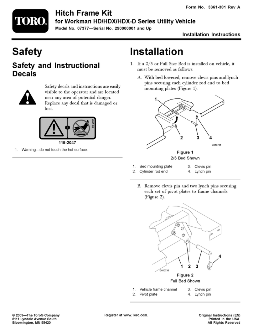
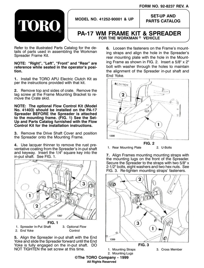
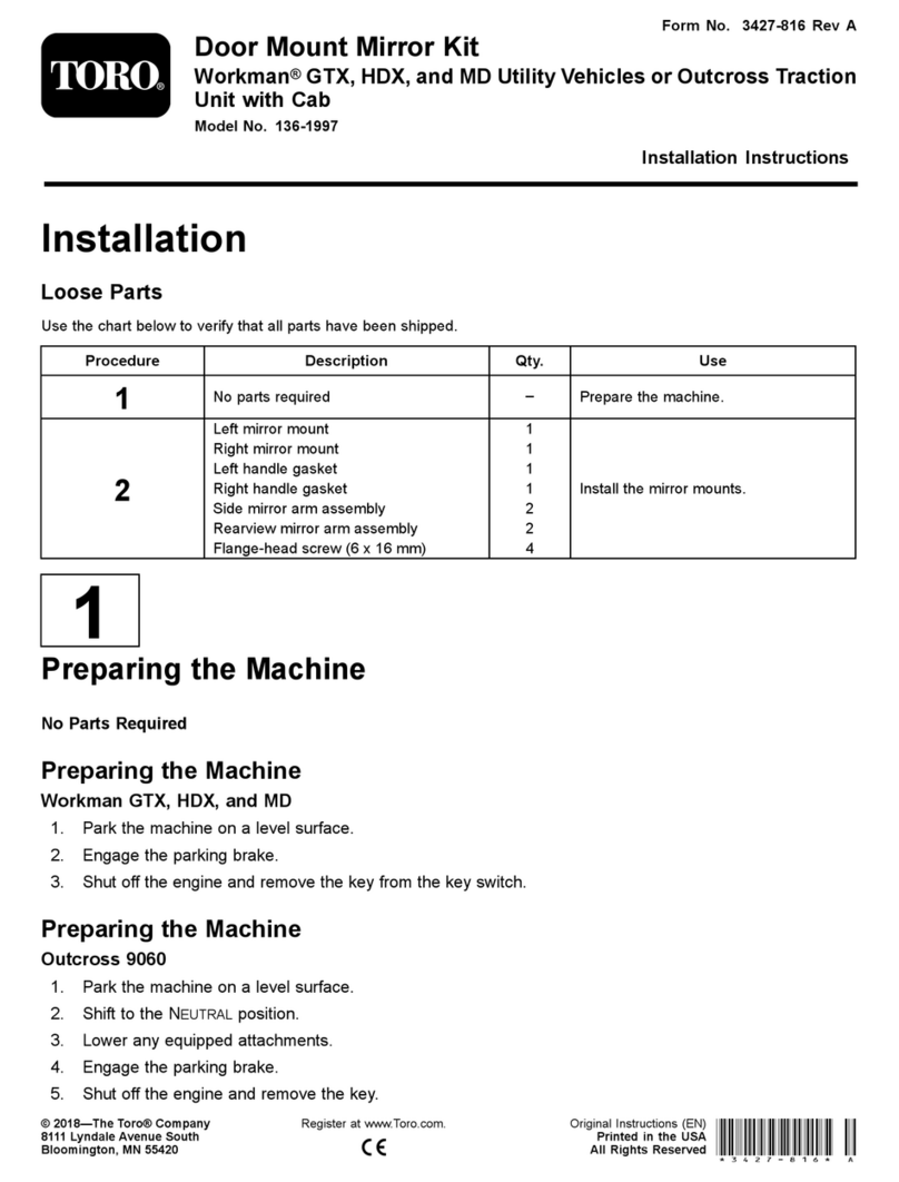
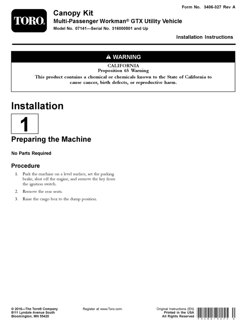
Toro Cab Kit User manual

FormNo.3432-927RevA
CabKit
Workman®GTXUtilityVehicle
ModelNo.07142—SerialNo.316000001andUp
ModelNo.07142—SerialNo.400000000andUp
Operator'sManual
Important:ThePowerConverterKitisrequired
tousethecabonaWorkmanGTXElectricutility
vehicle.ContactyourauthorizedTorodistributor
formoreinformation.
Important:TheSpringKitisrequiredtouse
thecabonaWorkmanGTXutilityvehicle.The
SpringKitshouldbeinstalledonlybyqualied
ToroServiceTechniciansusingapprovedtools.
Improperremoval,disassembly,orinstallationof
thespringassemblyposesadangertoyouand
bystanders.PleasecontactyourauthorizedToro
distributorfortheappropriatetoolsandproper
installationofthiskit.
Safety
WARNING
Thecompressedspringinthespringand
shockassemblyrepresentsastored-energy
hazard.Ifthespringisnotproperlyretained
duringcompressionorremoval,itcaninjure
youand/orbystanders.
•AlwaysusetheapprovedToro
spring-compressiontooltocompressthe
springinasecurepositionwhenremoving
theretentioncollar.
•Alwaysusecarewhenremovingpressure
fromthecompressedspring.
SafetyandInstructional
DecalsSafetydecalsandinstructionsare
easilyvisibletotheoperatorandare
locatednearanyareaofpotential
danger.Replaceanydecalthatis
damagedormissing.
decal133-1016
133-1016
1.Warning—readthe
Operator'sManual;wear
theseatbelt,andavoid
tippingthemachine.
2.Warning—wearhearing
protection.
©2019—TheToro®Company
8111LyndaleAvenueSouth
Bloomington,MN55420
Registeratwww.T oro.com.OriginalInstructions(EN)
PrintedintheUSA
AllRightsReserved*3432-927*A

decal133-1017
133-1017
1.Donotrepairorrevise—readtheOperator'sManual.
decal130-5964
130-5964
1.Warning—intheeventofanemergency1)Pullthelocking
pinoutofeachhinge;2)Pushthefrontwindowouttoexit.
decal131-8410
131-8410
1.Firehazard—shutofftheenginebeforefueling.
decal120-9570
120-9570
1.Warning—stayawayfrommovingparts,keepallguards
andshieldsinplace.
decal130-5439
130-5439
1.ReadtheOperator’sManualforinformationonfuses.4.Windshieldspray
2.Windshieldwiper—15A5.Windshieldwiper
3.Lights—15A
2

Setup
LooseParts
Usethechartbelowtoverifythatallpartshavebeenshipped.
ProcedureDescriptionQty.Use
1Nopartsrequired–Preparethemachine.
2Nopartsrequired–Removethestrutassembly(for2018
andbeforemachinesonly).
3Spring2Installthesprings(for2018andbefore
machinesonly).
4Nopartsrequired–Installthestrutassembly(for2018and
beforemachinesonly).
Floor-platesupport2
Flange-headbolt(5/16x1-1/4inches)16
Flangenut(5/16inch)16
Leftcabsupport1
Rightcabsupport1
Hex-headbolt(3/8x1-1/4inch)4
Flangenut(3/8inch)4
5
Washer(3/8inch)4
Installthesupports.
Cabframe1
Backfoamseal1
Backfoamsealcarpet1
Flange-headbolt(5/16x1-1/4inches)4
Flangenut(5/16inch)4
Flatwasher(5/16inch)4
Supportplate2
Right,frontfoamseal1
Left,frontfoamseal1
Upper,rearfoamseal1
Foamseal2
Hex-headbolt(3/8x1-1/4inches)6
Flangenut(3/8inch)6
6
Washer(3/8inch)6
Installthecab.
Fuseblock1
Hex-washerheadscrew(#10x3/4
inch)—for2019andafterelectric
machinesonly
2
Serratednut(#10)—for2019andafter
electricmachinesonly2
Self-tappingscrew—for2019andafter
gasolinemachinesonly2
7
Fuse(15A)1
Routethewireharness.
3

1
PreparingtheMachine
NoPartsRequired
Procedure
1.Parkthemachineonalevelsurface,settheparkingbrake,shutofftheengine,andremovethekey.
2.Raisethebeduntilthebedproprodisfullyengaged;refertotheOperator’sManualforthemachine.
3.Removetheseatbase.
4.Disconnectthenegativebatterycable;refertoyourOperator’sManual.
2
RemovingtheStrutAssembly
For2018andBeforeMachinesOnly
NoPartsRequired
Procedure
1.Removethefrontwheel.
2.Removethehex-headbolt(3/8x4-3/4inches)andangenut(3/8inch)fromthespindle(Figure1).
3.Removethehex-headbolt(3/8x3-1/2inches)andangenut(3/8inch)fromthecontrolarm(Figure1).
4.Removethehex-headbolt(1/2x2-1/4inches)andlocknut(1/2inch)securingthestrutassemblyto
theupperframe(Figure1).
5.Removethestrutassembly(Figure1).
Note:Repeatthisprocedurefortheothersideofthemachine.
4

g038284
Figure1
Hoodandfendernotshowntoshowtheshock-mountbracket
1.Hex-headbolt(1/2x2-1/4inches)6.Flangenut(3/8inch)—fromthecontrolarm
2.Locknut(1/2inch)7.Flangenut(3/8inch)—fromthespindle
3.Collar8.Hex-headbolt(3/8x3-1/2inches)—fromthecontrolarm
4.Spring9.Hex-headbolt(3/8x4-3/4inches)—fromthespindle
5.Strutassembly
5

3
InstallingtheSprings
For2018andBeforeMachines
Only
Partsneededforthisprocedure:
2Spring
Procedure
UseanapprovedT orospring-compressiontoolto
removeandinstallspringsofthestrutassembly.
ContactyourauthorizedTorodistributor.
1.Placethestrutassemblyintothecompression
toolandusethetooltocompressthespring.
2.Whilethespringiscompressed,removethe
collar.
3.Removethespringfromthestrutassembly
(Figure1).
4.Installthenewspringovertheexistingstrut
assembly(Figure1).
5.UsingtheT orospring-compressiontool,
compressthespring.
6.Whilethespringiscompressed,installthecollar.
7.Carefullyreleasepressureonthespring,
allowingittoseatonthecollar.
8.Removethestrutassemblyfromthe
compressiontool.
Note:Repeatthisprocedurefortheothersideofthe
machine.
4
InstallingtheStrut
Assembly
For2018andBeforeMachines
Only
NoPartsRequired
Procedure
1.Installstrutassemblytothemachine.
2.Securetheupperportionofthestrutassembly
totheframeusingtheupper,hex-headbolt(1/2
x2-1/4inches)andlocknut(1/2inch)asshown
inFigure1.
3.Torquethehex-headbolt(1/2x2-1/4inches)to
91to113N∙m(67to83ft-lb).
4.Installthehex-headbolt(3/8x4-3/4inches)and
angenut(3/8inch)tothespindle(Figure1).
5.Torquethehex-headbolt(3/8x4-3/4inches)to
37to45N∙m(27to33ft-lb).
6.Securethelowerportionofthestrutassembly
tothecontrolarmusingthehex-headbolt(3/8x
3-1/2inches)andangenut(3/8inch)asshown
inFigure1.
7.Torquethehex-headbolt(3/8x3-1/2inches)to
37to45N∙m(27to33ft-lb).
8.Installthefrontwheel.
Note:Repeatthisprocedurefortheothersideofthe
machine.
6

5
InstallingtheSupports
Partsneededforthisprocedure:
2Floor-platesupport
16Flange-headbolt(5/16x1-1/4inches)
16Flangenut(5/16inch)
1Leftcabsupport
1Rightcabsupport
4Hex-headbolt(3/8x1-1/4inch)
4Flangenut(3/8inch)
4Washer(3/8inch)
Procedure
1.Removethe4screws(1/4x1-1/4inches)and4
nuts(1/4inch)fromtheoorplate(Figure2).
g038333
Figure2
1.Nut(1/4inch)3.Floorplate
2.Screw(1/4x1-1/4inches)
2.Useaoorjackundertheframetosupportthe
frontofthemachine(Figure3).
g038334
Figure3
1.Frame
3.Remove1oftheexistingoor-platesupports
(Figure4).
Important:Donotremovebothofthe
existingoor-platesupportssimultaneously.
g035246
Figure4
1.Existingoor-platesupports
7

4.Installanewoor-platesupportusing8
ange-headbolts(5/16x1-1/4inches)and8
angenuts(5/16inch)asshowninFigure5.
Note:Torquetheange-headbolts(5/16x
1-1/4inches)to34N∙m(25ft-lb).
g035247
Figure5
1.Flangenut(5/16inch)3.Floor-platesupport
2.Flange-headbolt(5/16x
1-1/4inches)
5.Removetheotherexistingoor-platesupport
(Figure4).
6.Installtheothernewoor-platesupportusing8
ange-headbolts(5/16x1-1/4inches)and8
angenuts(5/16inch)asshowninFigure5.
7.Installthepreviouslyremoved4screws(1/4x
1-1/4inches)and4nuts(1/4inch)intotheoor
plate(Figure2).
8.Usingthenewoor-platesupportsasaguide,
drill3holes(3/8-inchdiameter)intoeachoor
plate(Figure6).
Important:Drillonlythefront2holesonthe
newoor-platesupportsandthefarthest,
rearhole;asshowninFigure6.
g038352
Figure6
1.Donotdrillthishole.2.Frontofthemachine
9.Looselyattachtheleftandrightcabsupports
tothemachineusingthehex-headbolts(3/8x
1-1/4inch),washers(3/8inch),andangenuts
(3/8inch)asshowninFigure7.
Note:Donottightentheboltsatthistime.
g037135
Figure7
1.Hex-headbolt(3/8x1-1/4
inch)
3.Flangenut(3/8inch)
2.Cabsupport4.Washer(3/8inch)
8

6
InstallingtheCab
Partsneededforthisprocedure:
1Cabframe
1Backfoamseal
1Backfoamsealcarpet
4Flange-headbolt(5/16x1-1/4inches)
4Flangenut(5/16inch)
4Flatwasher(5/16inch)
2Supportplate
1Right,frontfoamseal
1Left,frontfoamseal
1Upper,rearfoamseal
2Foamseal
6Hex-headbolt(3/8x1-1/4inches)
6Flangenut(3/8inch)
6Washer(3/8inch)
Procedure
1.Removethebackingfromthebackfoamseal
andattachthesealtothemachineasshown
inFigure8.
Important:Ensurethattheundersideofthe
backfoamsealwiththeadhesivefacesthe
topoftherailsurface.
g035251
Figure8
1.Backfoamseal
2.Removetheseatbase.
3.Removethe3screwsand3nutssecuringthe
lefthandhold,andremoveit(Figure9).
g037177
Figure9
1.Handhold
4.Installthefrontsealingfoamifitisnotalready
installed(Figure10).
Note:Ensurethatyouinstallthefrontsealing
foamontothecabbeforeyouinstallthecab
ontothemachine.
g038337
Figure10
1.Frontsealingfoam
9

5.Liftthecabframeusingtheliftpointsandplace
itonthemachine(Figure11).
g037103
Figure11
1.Liftpoints
6.Securethesidesofthecabframetothemachine
using6hex-headbolts(3/8x1-1/4inches),6
washers(3/8inch),and6angenuts(3/8inch)
asshowninFigure12.
Note:T orquethehex-headbolts(3/8x1-1/4
inches)to58N∙m(43ft-lb).
g037137
Figure12
1.Hex-headbolt(3/8x1-1/4
inches)
3.Flangenut(3/8inch)
2.Washer(3/8inch)
7.Securethebackofthecabframetotheleftand
rightsupportsusing4ange-headbolts(5/16x
1-1/4inches),2supportplates,4atwashers,
and4angenuts(5/16inch)asshowninFigure
13.
Note:Torquetheboltsto34N∙m(25ft-lb).
g035253
Figure13
1.Flange-headbolt(5/16x
1-1/4inches)
3.Flatwasher
2.Supportplate4.Flangenut(5/16inch)
8.Tightentheleftandrightsupports,andtorque
theboltsto58N∙m(43ft-lb)asshowninFigure
7.
9.Installthepreviouslyremovedlefthandhold
usingthe3screwsand3nuts(Figure9).
10.Installtheupper,rearfoamseal(Figure14).
g038338
Figure14
1.Upper,rearfoamseal
10

11.Installtheseatbase.
Note:Youmayneedtopositionthe2center
seat-beltanchorstoallowtheseattodropinto
place.Loosenthe2locknuts(7/16inch)onthe
2centerseat-beltanchors,andtightenthe2
locknuts(7/16inch)to72to88N∙m(53to65
ft-lb)afteradjustingtheposition.
12.Removethebackingfromtheright,frontand
left,frontfoamsealsandattachthesealstothe
machine(Figure15).
g035254
Figure15
1.Left,frontfoamseal
13.Removethebackingfromthefoamsealand
attachthesealtotherightsideofthemachine
(Figure16).
g037104
Figure16
RightSideShown
1.Foamseal
11

7
RoutingtheWireHarness
Partsneededforthisprocedure:
1Fuseblock
2Hex-washerheadscrew(#10x3/4inch)—for2019
andafterelectricmachinesonly
2Serratednut(#10)—for2019andafterelectric
machinesonly
2Self-tappingscrew—for2019andaftergasoline
machinesonly
1Fuse(15A)
ForElectricMachines
Important:ThePowerConverterKitisrequired
tousethecabonaWorkmanGTXElectricutility
vehicle.ContactyourauthorizedTorodistributor
formoreinformation.
1.Installthenewfuseblockasfollows:
•For2018andbeforemachines,snapthe
newfuseblockontotheexistingfuseblock
onthemachine(Figure17).
g035257
Figure17
1.Toground3.Totheoptionalwasher
pumpkit
2.Tothefusedwire4.Newfuseblock
•For2019andaftermachines,securethe
newfuseblockusingthe2hex-washerhead
screws(#10x3/4inch)and2serratednuts
(#10)asshowninFigure18.
g290937
Figure18
1.Newfuseblock3.Serratednut(#10)
2.Hex-washerheadscrew
(#10x3/4inch)
4.Femaleconnector
2.For2019andaftermachines,connectthe
femaleconnectorontheharnesstothenew
fuseblock(Figure18).
3.Connectthelargeconnectoronthenewfuse
blocktotheoptionalpowercableontheexisting
fuseblock(Figure17).
12

4.Routethewireharnessbehindthecaband
undertheseat,andsecurethecliponthewire
harnesstothesidepanel(Figure19).
g035260
Figure19
1.Wireharness
5.Installtheblackgroundwiretothegroundwire
onthePowerConverterKitwireharness(Figure
20).
Note:Theblackterminalringisnotused.
6.Installtheredpowerwiretothepowerwireon
thePowerConverterKitwireharness(Figure
20).
g278776
Figure20
1.Cabwireharness3.Blackgroundwirewith
spadeterminal
2.Blackgroundwirewith
terminalring(notused)
4.Redpowerwirewithspade
terminal
7.Connecttheremainingwiretothefusedwireon
thenewfuseblock(Figure17).
8.Lowerthebedandconnectthebattery;referto
theOperator’sManual.
9.Installthepreviouslyremovedseatbase.
13

ForGasoline/PetrolorEFI
Machines
1.Installthenewfuseblockasfollows:
•For2018andbeforemachines,snapthe
newfuseblockontotheexistingfuseblock
onthemachine(Figure17).
•For2019andaftermachines,securethe
newfuseblockusingthe2self-tapping
screwsasshowninFigure21.
g290831
Figure21
1.Self-tappingscrew2.Newfuseblock
2.Connectthelargeconnectoronthenewfuse
blocktotheoptionalpowercableontheexisting
fuseblock(Figure17).
3.Routethewireharnessbehindthecaband
undertheseat,andsecurethecliponthewire
harnesstothesidepanel(Figure19).
4.Installtheblackterminalringtothegroundblock
onthemachine(Figure22).
5.Installtheredpowerwireintoanemptysloton
themachinefuseblock(Figure22).
Note:Installanadditionalfuseblockifthere
arenoremainingslotsopeninafuseblock.
g278776
Figure22
1.Cabwireharness3.Blackgroundwirewith
spadeterminal
2.Blackgroundwirewith
terminalring
4.Redpowerwirewithspade
terminal
6.Connecttheremainingwiretothefusedwireon
thenewfuseblock(Figure17).
7.Lowerthebedandconnectthebattery;referto
theOperator’sManual.
8.Installthepreviouslyremovedseatbase.
14

ProductOverview
Controls
ControlPanel
Windshield-WiperSwitch
Clicktheswitchforwardtoactivatethewindshield
wipers(Figure23).
g026274
Figure23
1.Windshield-wipercontrol2.Lightswitch
LightSwitch
Pushtheleftorrightsideofthelightplatetoturnon
thecablight(Figure23).
WindshieldLatch
Liftuponthelatchestoopenthewindshield(Figure
24).Pressdownonthelatchtolockthewindshieldin
theopenposition.Pulloutanddownonthelatchto
closeandsecurethewindshield.
g026672
Figure24
1.Windshieldlatch
15

TheToroWarranty
Two-Yearor1,500HoursLimitedWarranty
ConditionsandProductsCovered
TheToroCompanyanditsafliate,ToroWarrantyCompany,pursuant
toanagreementbetweenthem,jointlywarrantyourToroCommercial
product(“Product”)tobefreefromdefectsinmaterialsorworkmanship
for2yearsor1,500operationalhours*,whicheveroccursrst.This
warrantyisapplicabletoallproductswiththeexceptionofAerators
(refertoseparatewarrantystatementsfortheseproducts).Wherea
warrantableconditionexists,wewillrepairtheProductatnocosttoyou
includingdiagnostics,labor,parts,andtransportation.Thiswarranty
beginsonthedatetheProductisdeliveredtotheoriginalretailpurchaser.
*Productequippedwithanhourmeter.
InstructionsforObtainingWarrantyService
YouareresponsiblefornotifyingtheCommercialProductsDistributoror
AuthorizedCommercialProductsDealerfromwhomyoupurchasedthe
Productassoonasyoubelieveawarrantableconditionexists.Ifyouneed
helplocatingaCommercialProductsDistributororAuthorizedDealer,or
ifyouhavequestionsregardingyourwarrantyrightsorresponsibilities,
youmaycontactusat:
ToroCommercialProductsServiceDepartment
ToroWarrantyCompany
8111LyndaleAvenueSouth
Bloomington,MN55420-1196
952–888–8801or800–952–2740
E-mail:[email protected]
OwnerResponsibilities
Astheproductowner,youareresponsibleforrequiredmaintenanceand
adjustmentsstatedinyourOperator'sManual.Repairsforproductissues
causedbyfailuretoperformrequiredmaintenanceandadjustmentsarenot
coveredunderthiswarranty.
ItemsandConditionsNotCovered
Notallproductfailuresormalfunctionsthatoccurduringthewarranty
periodaredefectsinmaterialsorworkmanship.Thiswarrantydoesnot
coverthefollowing:
•Productfailureswhichresultfromtheuseofnon-T ororeplacement
parts,orfrominstallationanduseofadd-on,ormodiednon-T oro
brandedaccessoriesandproducts.
•Productfailureswhichresultfromfailuretoperformrecommended
maintenanceand/oradjustments.
•ProductfailureswhichresultfromoperatingtheProductinanabusive,
negligent,orrecklessmanner.
•Partsconsumedthroughusethatarenotdefective.Examplesofparts
whichareconsumed,orusedup,duringnormalProductoperation
include,butarenotlimitedto,brakepadsandlinings,clutchlinings,
blades,reels,rollersandbearings(sealedorgreasable),bedknives,
sparkplugs,castorwheelsandbearings,tires,lters,belts,andcertain
sprayercomponentssuchasdiaphragms,nozzles,andcheckvalves.
•Failurescausedbyoutsideinuence,including,butnotlimitedto,
weather,storagepractices,contamination,useofunapprovedfuels,
coolants,lubricants,additives,fertilizers,water,orchemicals.
•Failureorperformanceissuesduetotheuseoffuels(e.g.gasoline,
diesel,orbiodiesel)thatdonotconformtotheirrespectiveindustry
standards.
•Normalnoise,vibration,wearandtear,anddeterioration.Normal
“wearandtear”includes,butisnotlimitedto,damagetoseatsdueto
wearorabrasion,wornpaintedsurfaces,scratcheddecalsorwindows.
Parts
Partsscheduledforreplacementasrequiredmaintenancearewarranted
fortheperiodoftimeuptothescheduledreplacementtimeforthatpart.
Partsreplacedunderthiswarrantyarecoveredforthedurationofthe
originalproductwarrantyandbecomethepropertyofT oro.Torowillmake
thenaldecisionwhethertorepairanyexistingpartorassemblyorreplace
it.T oromayuseremanufacturedpartsforwarrantyrepairs.
DeepCycleandLithium-IonBatteryWarranty
DeepcycleandLithium-Ionbatterieshaveaspeciedtotalnumber
ofkilowatt-hourstheycandeliverduringtheirlifetime.Operating,
recharging,andmaintenancetechniquescanextendorreducetotal
batterylife.Asthebatteriesinthisproductareconsumed,theamount
ofusefulworkbetweenchargingintervalswillslowlydecreaseuntilthe
batteryiscompletelywornout.Replacementofwornoutbatteries,
duetonormalconsumption,istheresponsibilityoftheproductowner.
Note:(Lithium-Ionbatteryonly):Pro-ratedafter2years.Refertothe
batterywarrantyforadditionalinformation.
LifetimeCrankshaftWarranty(ProStripe02657Model
Only)
TheProstripewhichisttedwithagenuineT oroFrictionDiscand
Crank-SafeBladeBrakeClutch(integratedBladeBrakeClutch(BBC)+
FrictionDiscassembly)asoriginalequipmentandusedbytheoriginal
purchaserinaccordancewithrecommendedoperatingandmaintenance
procedures,arecoveredbyaLifetimeWarrantyagainstenginecrankshaft
bending.Machinesttedwithfrictionwashers,BladeBrakeClutch(BBC)
unitsandothersuchdevicesarenotcoveredbytheLifetimeCrankshaft
Warranty.
MaintenanceisatOwner’sExpense
Enginetune-up,lubrication,cleaningandpolishing,replacementoflters,
coolant,andcompletingrecommendedmaintenancearesomeofthe
normalservicesT oroproductsrequirethatareattheowner’sexpense.
GeneralConditions
RepairbyanAuthorizedToroDistributororDealerisyoursoleremedy
underthiswarranty.
NeitherTheToroCompanynorToroWarrantyCompanyisliablefor
indirect,incidentalorconsequentialdamagesinconnectionwiththe
useoftheToroProductscoveredbythiswarranty,includingany
costorexpenseofprovidingsubstituteequipmentorserviceduring
reasonableperiodsofmalfunctionornon-usependingcompletion
ofrepairsunderthiswarranty.ExceptfortheEmissionswarranty
referencedbelow,ifapplicable,thereisnootherexpresswarranty.All
impliedwarrantiesofmerchantabilityandtnessforusearelimitedto
thedurationofthisexpresswarranty.
Somestatesdonotallowexclusionsofincidentalorconsequential
damages,orlimitationsonhowlonganimpliedwarrantylasts,sotheabove
exclusionsandlimitationsmaynotapplytoyou.Thiswarrantygivesyou
speciclegalrights,andyoumayalsohaveotherrightswhichvaryfrom
statetostate.
NoteRegardingEmissionsWarranty
TheEmissionsControlSystemonyourProductmaybecoveredby
aseparatewarrantymeetingrequirementsestablishedbytheU.S.
EnvironmentalProtectionAgency(EPA)and/ortheCaliforniaAirResources
Board(CARB).Thehourlimitationssetforthabovedonotapplytothe
EmissionsControlSystemWarranty.RefertotheEngineEmissionControl
WarrantyStatementsuppliedwithyourproductorcontainedintheengine
manufacturer’sdocumentation.
CountriesOtherthantheUnitedStatesorCanada
CustomerswhohavepurchasedT oroproductsexportedfromtheUnitedStatesorCanadashouldcontacttheirT oroDistributor(Dealer)toobtain
guaranteepoliciesforyourcountry,province,orstate.IfforanyreasonyouaredissatisedwithyourDistributor'sserviceorhavedifcultyobtaining
guaranteeinformation,contactyourAuthorizedT oroServiceCenter.
374-0253RevF
This manual suits for next models
1
Table of contents
Other Toro Automobile Accessories manuals
Popular Automobile Accessories manuals by other brands

Thule
Thule DOUBLETRACK 990XT installation instructions
WeatherTech
WeatherTech No-Drill MudFlap installation instructions
Tessera4x4
Tessera4x4 SOT-ROLL Series installation manual

Innogy
Innogy ePole installation instructions
Safe Fleet
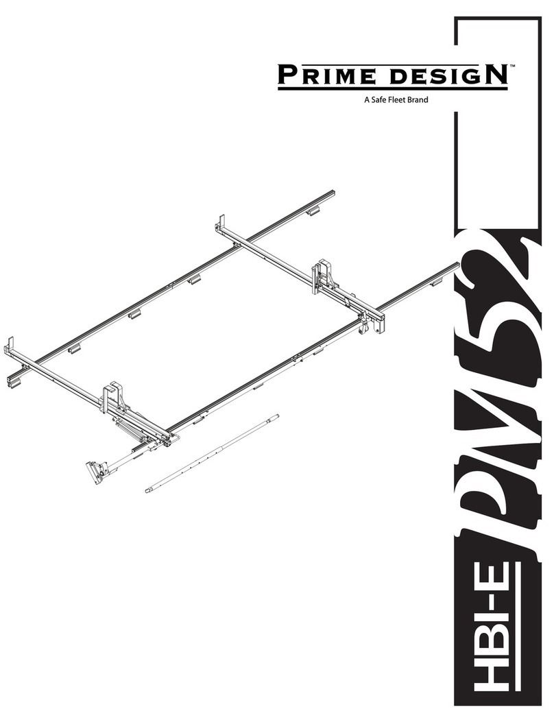
Safe Fleet PRIME DESIGN HBI-E-PM52 manual
Cub Cadet
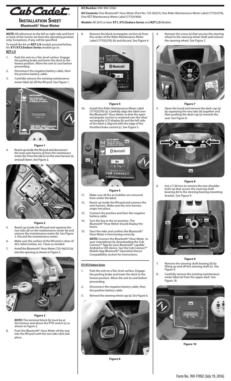
Cub Cadet 490-900-C066 Installation sheet

