Toro PA-17 WM Instruction Manual

1
Refer to the illustrated Parts Catalog for the de-
tails of parts used in assembling the Workman
Spreader Frame Kit.
NOTE: Right, Left, Front and Rear are
reference while seated in the operators posi-
tion.
. Install the T R APU Electric Clutch Kit as
per the instructions provided with that kit.
2. Remove top and sides of crate. Remove the
lag screw at the Frame Mounting Bracket to re-
move the Crate skid.
NOTE: The optional Flow Control Kit (Model
No. 4 403) should be installed on the PA- 7
Spreader BEFORE the Spreader is attached
to the mounting frame. (FIG. ) See the Set-
Up and Parts Catalog furnished with the Flow
Control Kit for the installation instructions.
3. Remove the Drive Shaft Cover and position
the Spreader onto the Mounting Frame.
4. Use lacquer thinner to remove the rust pre-
ventative coating from the Spreaders in-put shaft
and keyway. Insert the 1/4" square key into the
in-put shaft. See FIG. 1.
FIG.
1. Spreader In-Put Shaft 3. ptional Flow
2. End Yoke Control
5. Align the Spreader in-put shaft with the End
Yoke and slide the Spreader forward until the End
Yoke is fully engaged on the in-put shaft. D
N T TIGHTEN the set screw at this time.
FORM NO. 92-8237 REV. A
MODEL NO. 4 252-9000 & UP
PA- 7 WM FRAME KIT & SPREADER
FOR THE WORKMAN R VEHICLE
SET-UP AND
PARTS CATALOG
6. Loosen the fasteners on the Frames mount-
ing straps and align the hole in the Spreaders
rear mounting plate with the hole in the Mount-
ing Frame as shown in FIG. 2. Insert a 5/8" x 2"
bolt with washer through the holes to maintain
the alignment of the Spreader in-put shaft and
End Yoke.
FIG. 2
1. Rear Mounting Plate 2. U-Bolts
7. Align Frames mounting mounting straps with
the mounting lugs on the front of the Spreader.
Secure the Spreader to the straps with two 5/8" x
2-1/2" bolts, eight washers and two hex nuts. See
FIG. 3. Re-tighten mounting straps fasteners.
1. Mounting Straps 3. Cross Member
2. Mounting Lugs
FIG. 3
1398
1399
©The TORO Company - 999
All Rights Reserved
1397
2
8. Lift and secure the Mounting Frame and
Spreader approximately 12 inches above ground
level for easier access to fasteners used in secur-
ing the Spreader to the Mounting Frame.
9. Install hex nut and washer to 5/8" x 2" bolt at
rear mounting plate. See FIG. 2.
0. Insert two U-bolts over the tubular frame
of the Spreader and secure with four 3/8" flat
washers and lock nuts (FIG. 2).
. Secure the cross member of the Spreader
to the Mounting Frame with two 3/8" x 1" bolts,
four washers, and lock nut. See FIG. 3.
2. Tighten all fasteners securely. Apply thread
locking adhesive and tighten the set screw in the
End Yoke. Re-install the Drive Shaft Cover.
3. Install the Edge Trim on the Radiator Cover.
Mount the Radiator Cover on the Vehicle Frame
and secure with four 3/8" x 1" bolts and flat wash-
ers. n some models, it may be necessary to use
two nuts at rear holes.
4. Locate and remove two 1/2" bolts on each
side of the Workman frame and install the Attach-
ment Mounting Brackets, using the bolts and nuts
removed earlier. See FIG 4. Tighten the nuts
and bolts securely.
1. Attachment Mounting Bracket
NOTE: If the Workman vehicle is equipped
with the optional PTO Kit, remove the bottom
fasteners, loosen the top fasteners and tilt the
PTO Shield downward. This is necessary BE-
FORE the Mounting Frame can be assembled
to the Workman Frame.
5. Position the assembled Spreader and
Mounting Frame onto the Workman.
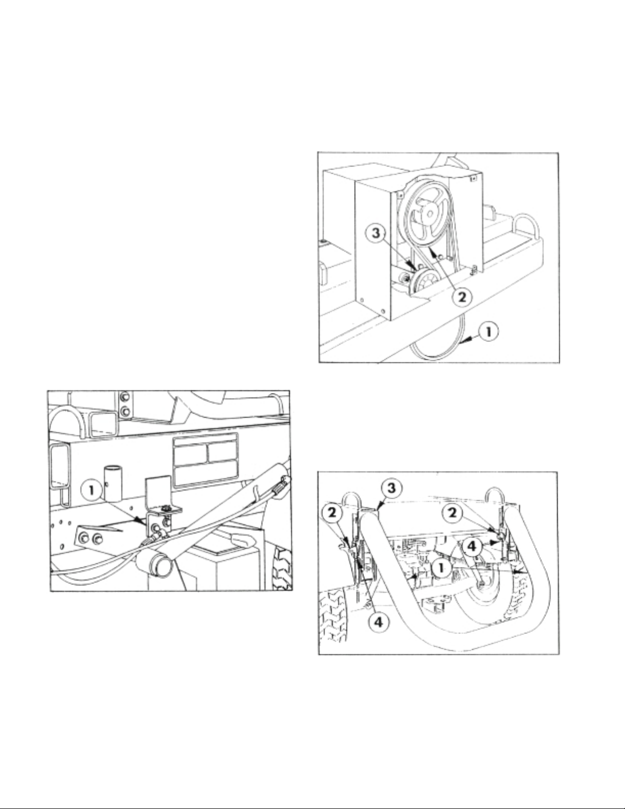
7. Remove the Knobs to release the hinged
door on the Belt Cover and install the Spreader
Spring as shown in FIG. 5. Install the Drive Belt
between the Gear Reducer Pulley and the
Workmans Electric Clutch Pulley. Close the cover
and re-install Knobs.
1. Drive Belt 3. Idler Pulley
2. Gear Reducer Pulley 4. Idler Spring
8. Mount the Rear Support to the Mounting
Frame and secure with two 1/2" x 3-1/4" bolts,
four flat washers, and two lock nuts on each side
of the Mounting Frame. Do not tighten bolts. See
FIG. 6.
1. Rear Support 3. Support Tube Plates
2. Mounting Pin 4. Lynch Pin
9. Slide the two 3/4" x 4-3/8" Mounting Pins
through the Support Tube Plates and the
Workmans frame. Secure with two Lynch Pins
on each Mounting Pin. Torque fasteners for Rear
Support to 75 ft. lbs.
FIG. 4
FIG. 5
FIG. 6
6. Secure the Mounting Frame to the Attach-
ment Mounting Brackets with two 1/2" x 1-1/2"
bolts four washers and lock nuts. See FIG. 4.
1400
1401
1402
3
If the Spreader is NOT EQUIPPED with the
optional Flow Control Kit, proceed as follows:
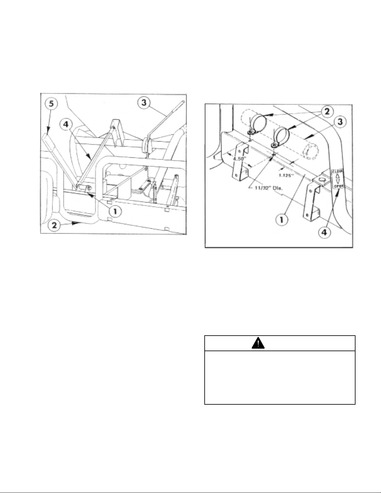
. Install the Lever Bracket Assembly on the
Workmans Seat Frame as shown in FIG. 7. Se-
cure with four 5/16" x 3/4" carriage bolts and nuts.
1. Lever Bracket Assy 4. Lever Bracket Brace
2. Seat Frame 5. Flow Control Handle
3 Flow Regulator Handle (in Close position)
(in Close Position)
2. Apply rust preventive oil to the Pivot Sleeve
and slide it inside the pivot tube on the Lever
Bracket Assembly, position a 1/2" flat washer and
insert the 1/2" x 4" bolt through the washer, the
pivot tube, the Lever Bracket Brace and the Con-
trol Lever. Secure with a lock nut.
3. Install the Lever Bracket Brace to the hole in
the Spreaders frame, using a 5/8" x 1-1/2" screw,
two washers and a lock nut.
4. Position the Flow Regulator and Flow Control
Handles in their CLOSE position as shown in FIG.
7.
5. Insert the Linkage Rod into the lower hole of
the Control Lever and secure with two 1/2" flat
washers and cotter pin.
6. Attach the adjustable clevis on the other end
of the Linkage Rod to the Spreaders Flow Regu-
lator Handle with a 1/2" x 1-1/2" clevis pin, two
washers and hairpin cotter. NOTE: The effec-
tive length of the Linkage can be shortened
or lengthened by loosening the jam nut and
turning the Adjustable Clevis. When length is
correct, re-tighten the jam nut.
Shown With R.H. Seat Back Removed
7. Position the Muaual Tube the passenger hand
side of the Seat Back Rest Channel, it will have to
be moved to the right hand side, with R-Clamps
posiotioned as shown in FIG. 8. If the existing hole
in that locatoin proceed as follows:
8. Using dimensions shown, locate, mark and
drill an 11/32" dia. hole in top of the right hand
Seat Back Rest Channel. Use a file to make a
square hole of the 11/32" dia. hole (for the car-
riage bolt head.)
NOTE: If the Spreader IS EQUIPPED with the
optional Flow Control Kit, skip Steps thru 6
and proceed to Step 7.
FIG. 7
FIG. 8
1403 1404
1. Back Rest Channel 3. Manual Tube
2. R-Clamps 4. pen/Close Decal
9. Re-install the R-Clamps and Manual Tube on
the right hand side of the channel, using the fas-
teners previously removed and hex nut provided.
See FIG. 8.
0. Remove backing and affix pen/Close De-
cal on Seat Frame. See FIG. 8.
DANGER
AN OVERLOADED SPREADER HOP-
PER CAN CAUSE A TIP OVER RESULT-
ING IN SERIOUS INJURY OR DEATH.
l Install the Level Limit and Capacity
700 LBS. Decals as instructed.
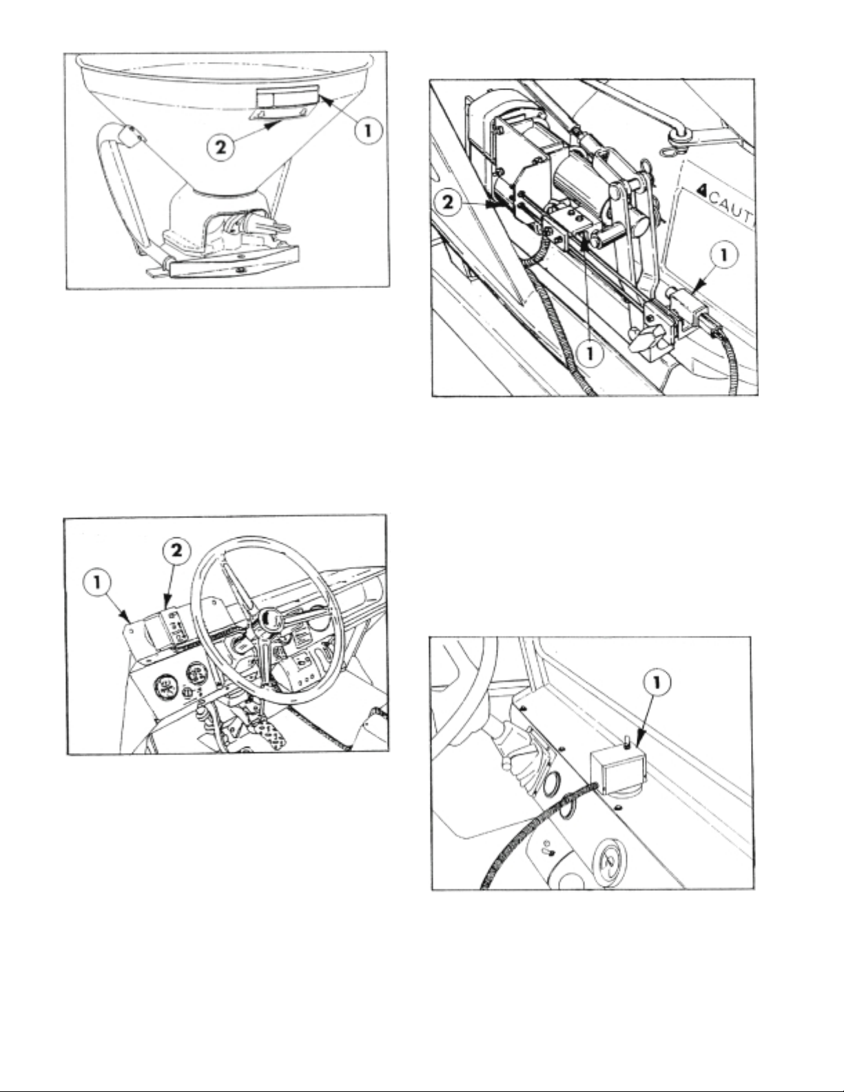
. Remove the backing and affix the Maximum
Sand Level Decal directly below the existing Ca-
pacity 1000 LBS. Decal, on the back of the
Spreader Hopper. See FIG. 9.
4
top of the Workman frame. Install Grommet in
hole.
7. Attach the Magnet and Control Box to the front
of the Enclosure as shown in FIG. 10.
1408
FIG. 2
1. Control Box
8. Re-connect the Wiring Harness to the Actua-
tor and Limit Switches.
9. Connect battery wires from the Wiring Har-
ness to the Workman Vehicles battery as de-
scribed in the Flow Control Kit instructions.
1. Limit Switch 2. Actuator
5. Slide the Grommet over the connectors.
6. Measure and mark the location, to drill a 2"
dia. hole in the rear of the Enclosure. Locate the
hole in a convenient location near the center of
the Enclosure, approximately 24 inches from the
1. Capacity 700 LBS. 2. Maximum Sand Level
Decal Decal
2. Remove the backing and affix the Capac-
ity 700 LBS. Decal over the Capacity 1000 LBS.
Decal, so it is completely covered.
INSTRUCTIONS FOR SPREADER EQUIPPED
WITH THE OPTIONAL FLOW CONTROL KIT:
. Remove two screws on the Workman dash
panel and use them to attach the Control Con-
sole Bracket to dash as shown in FIG. 10.
1. Console Mounting Brkt 2. Control Box
2. Route the Wiring Harness and Control Box
forward along the left side of the Workman frame
and connect the two battery wires to the Battery,
as described in the Flow Control Instructions.
3. Attach the Magnet and Control Box to the
Bracket attached to the Workman dash panel in
Step 22.
INSTRUCTIONS FOR SPREADER EQUIPPED
WITH THE OPTIONAL FLOW CONTROL, TO
BE USED ON WORKMAN EQUIPPED WITH
OPTIONAL ENCLOSURE.
4. Disconnect the Wiring Harness at the Actua-
tor and the two Limit Switches.
FIG. 9
FIG. 0
FIG.
1405
1407
1406
5
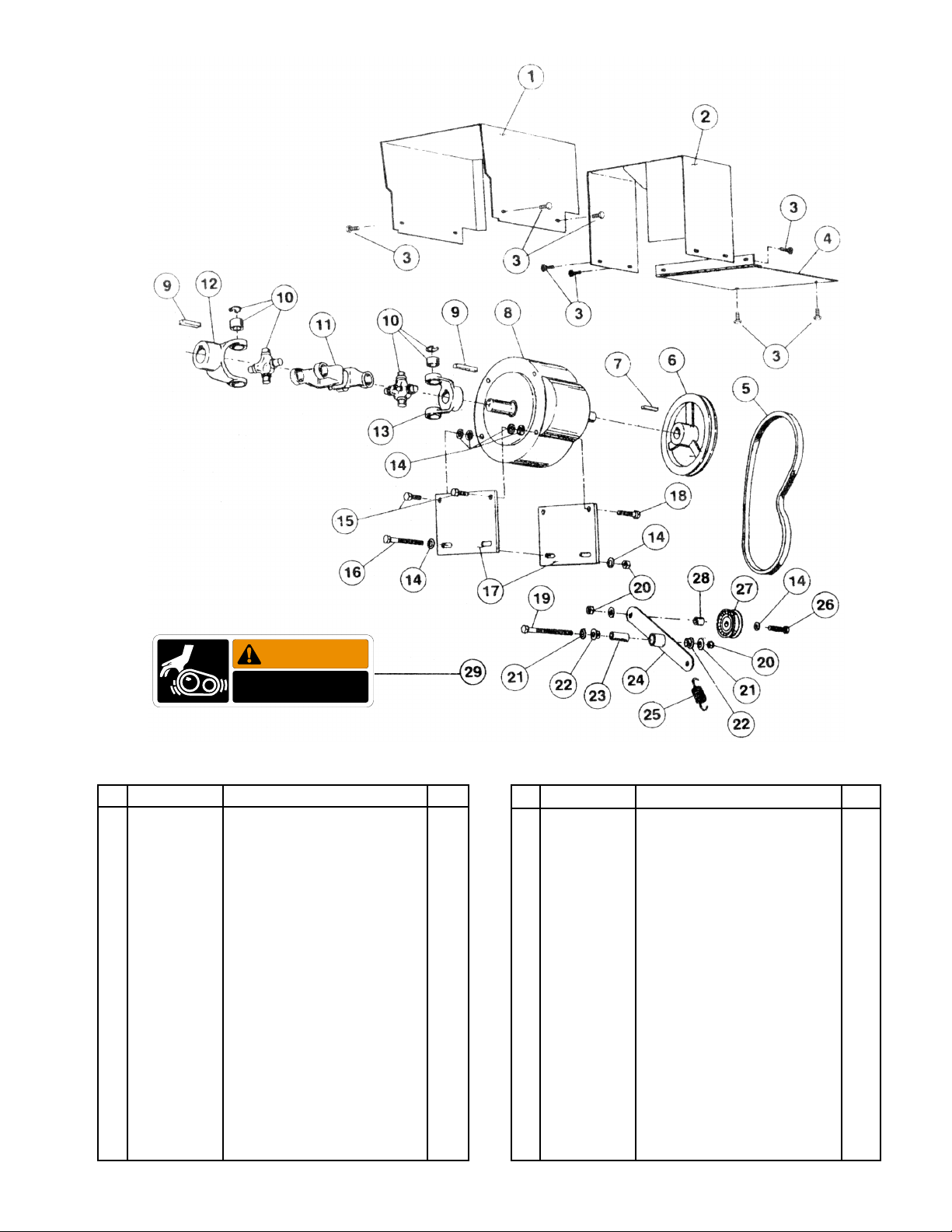
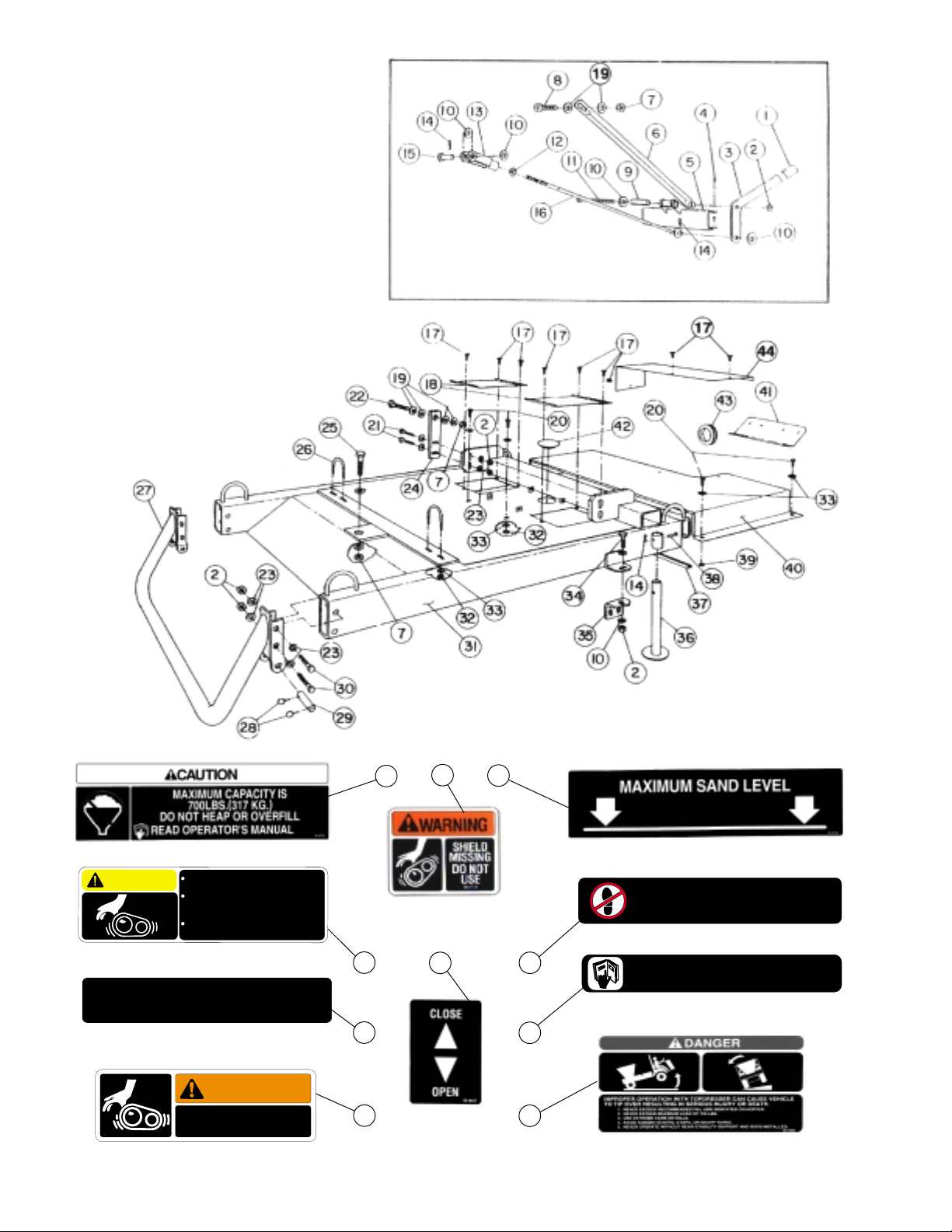
Ref Part No. Description Qty
1 93-6431 Drive Shaft Cover 1
2 92-8270 Belt Cover 1
3 32104-95 HWH - Self Tapping Screw 12
1/4 x 5/8"
4 92-8219 Belt Cover Door 1
5 92-8249 Drive Belt 1
6 92-8204 Speader Pulley 1
7 314110 Square Key, 3/16 x 1" 1
8 043003 Gear Multiplier 5:1 1
9 314233 Square Key, 1/4 x 1-1/2" 2
10 42554 Journal & Bearing 2
3247-3 Set Screw, 3/8 NC x 1/2" 4
11 43004 Double Center Yoke 1
12 42552 End Yoke, 1-3/16" Dia. 1
13 42553 End Yoke, 1" Dia. 1
14 3256-24 Flat Washer, 3/8" S.A.E. 10
Ref Part No. Description Qty
15 323-6 HHCS, 3/8 NC x 1" 2
16 323-38 HHCS , 3/8 NC x 4-3/4" 2
17 92-8205 Gearbox Plate 2
18 323-10 HCS, 3/8 NC x 5-1/2" 2
19 323-25 HHCS, 3/8 NC x 5-1/2" 1
20 32153-2 Lock Nut 4
21 3256-4 Flat Washer, 3/8" 2
22 256-258 Nylon Flange Bushing 2
23 92-8202 Idler Pivot Sleeve 1
24 92-8199 Idler Arm Ass'y 1
25 54-2730 Idler Spring 1
26 323-9 HHCS, 3/8 x 1-3/4" 1
27 041353 Idler Pulley 1
28 41488 Idler Spacer 1
29 80-8040 Decal - Rotating Members 1
SPREADER DRIVE
1409
WARNING
ROTATING MEMBERS
80-8040
6
NO RIDERS
75-5190
WARNING
ROTATING MEMBERS
80-8040
CAUTION
TO AVOID PERSONAL INJURY KEEP
ALL SHIELDS IN PLACE.
DISENGAGE AND SHUT OFF
ENGINE BEFORE SERVICING OR
UNCLOGGING MACHINE.
KEEP HANDS, FEET AND CLOTHING
AWAY FROM POWER-DRIVEN PARTS.
87-0450
NO STEP
36-3400
READ YOUR OPERATOR’S MANUAL FOR OPERATING AND
SAFETY INSTRUCTIONS. TO GET A REPLACEMENT MANUAL,
SEND MODEL AND SERIAL NUMBERS TO : THE TORO CO., 8111
LYNDALE AVE. S., MPLS., MN 55420
65-3090
Part No. 75-5190: Located on rear Rear Cover
2 - Located on sides of Rear Support Tube.
2 Located on Radiator Cver.
Part No. 80-8040: 2 - Locatied on Radiator Cover.
1 - Located on Belt Cover.
Part No. 65-3090: Located on top of Front Tube
Crossmember.
Part No. 36-3400: Located on Radiator Cover.
Part No. 87-0450: Located on top of Front Tube
Crossmember.
Part No. 92-4366: Located on R. H. and
L.H. side of Frame.
Part No. 88-8950: 1- Located
on Frame under Belt Cover.
1 - Located under PT .
Part No. 92-2741: Located on rear of Spreader Hopper. Part No.92-2742: Located on Hopper below
Decal No. 92-2741
Part No. 92-4447:
Located on Seat
Bar next to
Spreader Lever.
1410
THESE PARTS ARE N T USED WITH PTI NAL FL W
C NTR L KIT.
45 47 46
53 51
49
50
48
52
54

7
Ref Part No. Description Qty Ref Part No. Description Qty
SPREADER DRIVE
Lever Grip
Lock Nut, 1/2 NC
Lever
Carriage Bolt, 5/16 NC x 3/4"
Lever Pivot Bracket
Lever Bracket Brace
Lock Nut, 5/8 NC
HHCS, 5/8 NC x 1-1/2
Pivot Sleeve
Flat Washer, 1/2 USS
HHCS, 1/2 NC x 4"
Hex Jam Nut, 1/2" NF
Adjustable Clevis 1/2"
Hair Pin
Clevis Pin, 1/2 x 1-1/2"
Linkage Bar
HWH - Self Tapping Screw
1/4 x 5/8"
Service Door
Flat Washer, 5/8 USS
HHCS, 3/8 NC x 1"
HHCS, 1/2 NC x 2"
HHCS, 5/8 NC x 2-1/2"
Flat Washer, 1/2 SAE
Spreader Mount Plate
HHCS, 5/8 NC x 2
U-Bolt
Rear Support Tube (With decals)
Lynch Pin
Mounting Pin
92-8229
32153-5
92-8228
3230-1
92-8223
92-8230
32153-15
327-4
92-8235
3256-6
325-17
3220-5
92-0302
328967
283-68
92-8231
32104-57
92-8211
3256-7
323-6
325-8
327-7
3256-26
92-8210
327-6
92-2752
92-8269
92-1298
92-1233
1
11
1
4
1
1
4
1
1
10
1
1
1
4
1
1
9
2
12
6
4
2
16
2
1
2
1
4
2
1
2
3
4
5
6
7
8
9
10
11
12
13
14
15
16
17
18
19
20
21
22
23
24
25
26
27
28
29
HHCS, 1/2 NC x 3-1/4
Frame Ass'y. (With decals)
Lock Nut, 3/8 NC
Flat Washer, 3/8 USS
HHCS, 1/2 NC x 1-1/2"
Attachment Mounting Bracket
Jack Stand
Cover Trim
Clevis Pin, 1/2 x 2"
Hex Nut, 3/8 NC
Radiator Cover (With decals)
Trim 5-5/8" Long
Trim 26" Long
Control Console Bracket
(Flow Control w/o Enclosure)
Hole Plug, 3-1/2"
Grommet
(Flow Control w/ Enclosure)
Radiator Panel
(Air-cooled WM only)
Decal - Capacity 700 lbs.
Decal - Sand Level
Decal - Warning
Decal - No Sept
Decal - No Riders
Decal - Rotating Members
Decal - pen/Close
Decal - Read Manual
Decal - Personal Injury
Decal - Danger Tip
325-13
92-8291
32153-2
3256-4
325-6
92-2667
92-8250
92-8233
42195
3217-7
93-6199
9203627
42657
92-3679
42591
40764
93-6427
92-2741
92-2742
88-8950
36-3400
75-5190
80-8040
92-4447
65-3090
87-0450
92-4366
4
1
6
8
2
2
2
1
2
2
1
1
1
1
1
1
1
1
1
2
2
5
2
1
1
2
2
30
31
32
33
34
35
36
37
38
39
40
41
42
43
44
45
46
47
48
49
50
51
52
53
54

8
REF PART NO. DESCRIPTION QTY
GEAR MULTIPIER, 5:
1411
250 Housing Half
250 Housing Half
250 Gear, INTG HEL LH, 15T
250 Gear, HEL RH , 75T
250 Shim, .002 Red
250 Shim, .005 Blue
Spec. Shaft - utput
Ball Bearing
Cup Bearing
Cone Bearing
HHCS 3/8 NC x 1-3/4 (Grade 5)
Key, 3/16 sq x 3/4
Dowell Pin, 1/4 x 3/4
Seal
Seal
Skt. Pipe Plug, 1/4 NPT
43047
43048
43049
43050
43051
43052
43053
43054
43055
43056
323-9
43057
43058
43061
43060
43059
1
1
1
1
2
2
1
2
2
2
4
1
2
1
1
4
1
2
3
4
5
6
7
8
9
10
11
12
13
14
15
16
This manual suits for next models
1
Other Toro Automobile Accessories manuals


Popular Automobile Accessories manuals by other brands


Conceptronic
Conceptronic CCARHOLDTAB Multi Language Quick Guide

travall
travall TDG 1604 Fitting instructions

Spinder
Spinder RT1 Assembly instruction and safety regulations

Costway
Costway AT5565 user manual

Havis-Shields
Havis-Shields 18" Vehicle Specific Console for '04-08 Ford Econoline Van... Brochure & specs

Michelin
Michelin Wheely-Safe FITMENT PROCEDURE


