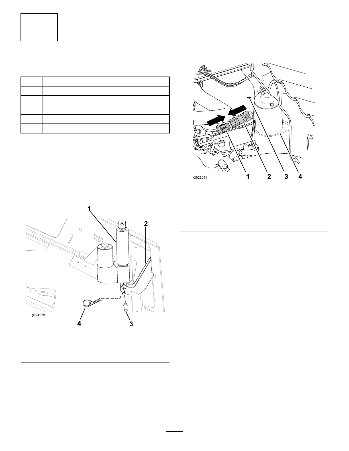
7.Presstheuppaddlethebed-liftswitchtoextend
therodoftheliftactuatorroduntiltheholeinthe
rodisalignswiththeholesintheinboardand
outboard-liftbrackets(Figure11).
Note:Selectthesetofholesinthebracket
forthegasolineanddieselmachines;referto
SafetyandInstructionalDecals(page1)forthe
holelocationsforthismachine.
g025012
Figure11
1.Locknut(1/2inch)5.Lift-actuatorrod
2.12.7mm(1/2inch)hole
forthehex-headbolt
6.12.7mm(1/2inch)hole
fortheclevispin
3.Hex-headbolt(1/2x5-1/2
inches)
7.Clevispin(3-1/2inches)
4.Hairpin
8.Securethelift-actuatorrodtotheliftbrackets
withtheclevispin(3-1/2inches)andhairpin
(Figure11).
Note:Tightenthelocknutandangenutuntil
theyaresnug.
9.Tightenthe4bolts(5/16x3/4inch)thatsecure
theinboardandoutboard-liftbracketstothebed
(Figure5)to15to16.6N-m(133to147in-lb).
10.Alignthehex-headbolt(1/2x5-1/2inches)
throughtheremaining12.7mm(1/2inch)holes
intheinboardandoutboard-liftbrackets(Figure
11)andsecureitwithalocknut(1/2inch)until
thenutissnug.
11.Tightentheangenutthatsecuresthebolt(5/16
inch)untilitissnug(Figure6).
5
RemovingthePropRod
NoPartsRequired
Procedure
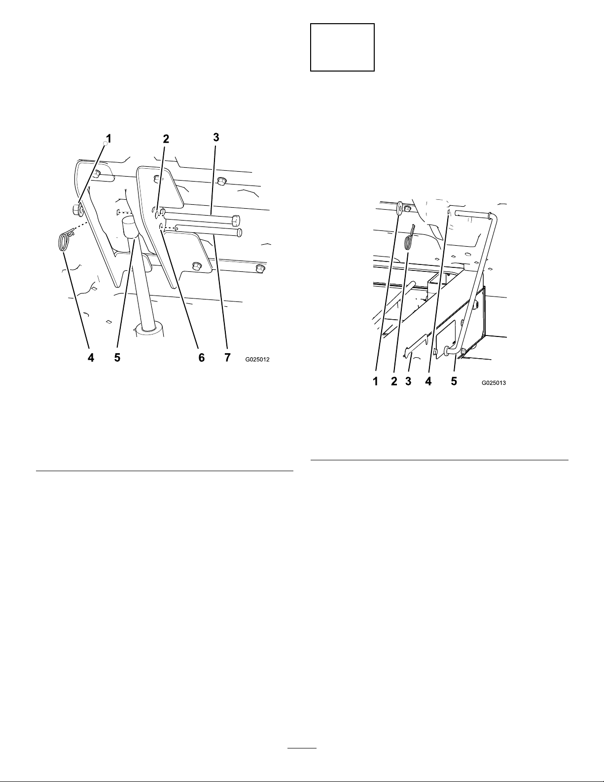
1.Removethehairpinandwasherthatsecurethe
proprodtothebottomofthebed(Figure12).
g025013
Figure12
1.Washer4.Bedhole
2.Hairpin5.Proprod
3.Slot(frame)
2.Slidetheproprodforwardtoremoveitfromthe
bracketontheframe(Figure12).
Note:Retaintheproprodcomponentsfor
futureuse.
Note:Iftheelectricboxliftiseverremoved,
installtheproprodandlatchrodagain,using
theexistingfastenersandtheprop-rodbracket.
8