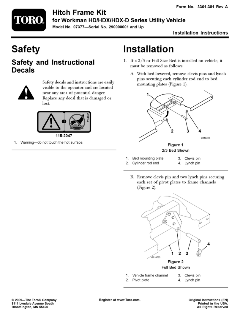
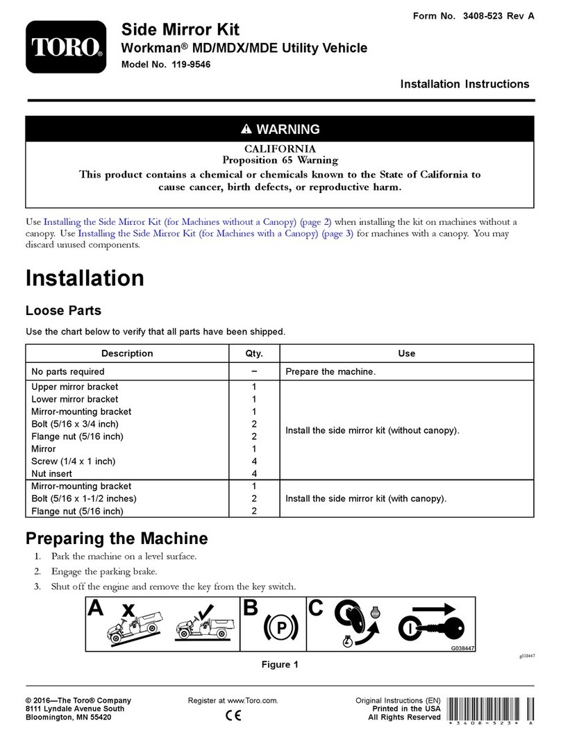
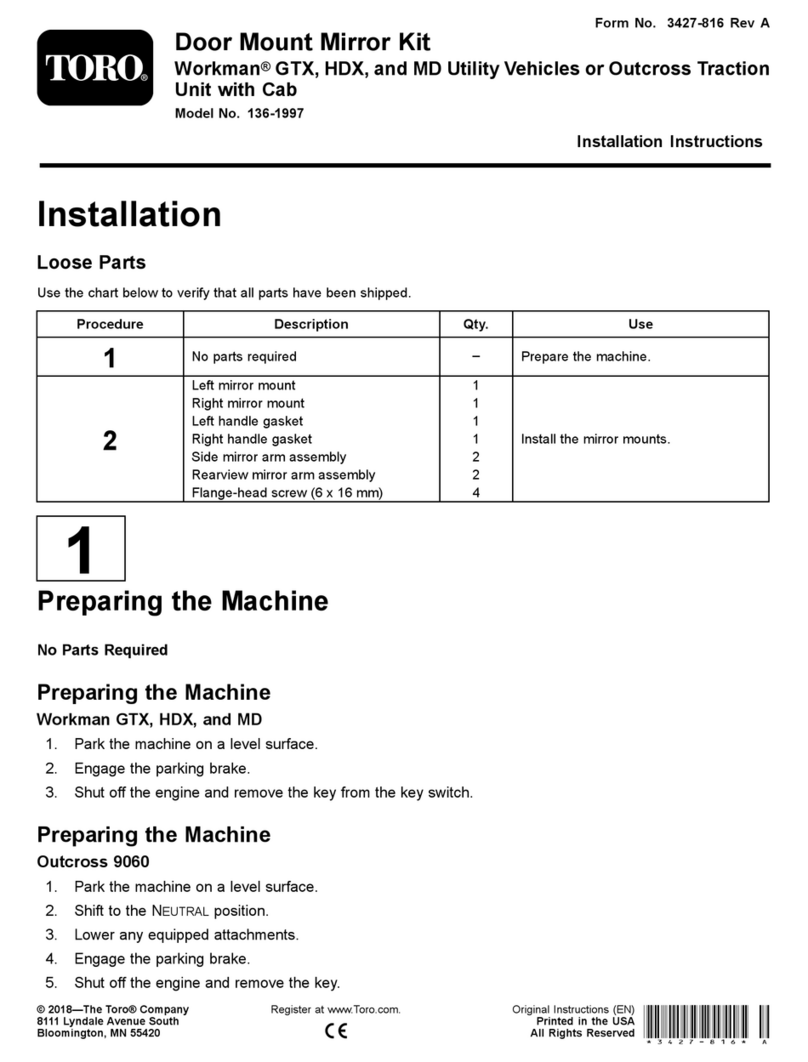
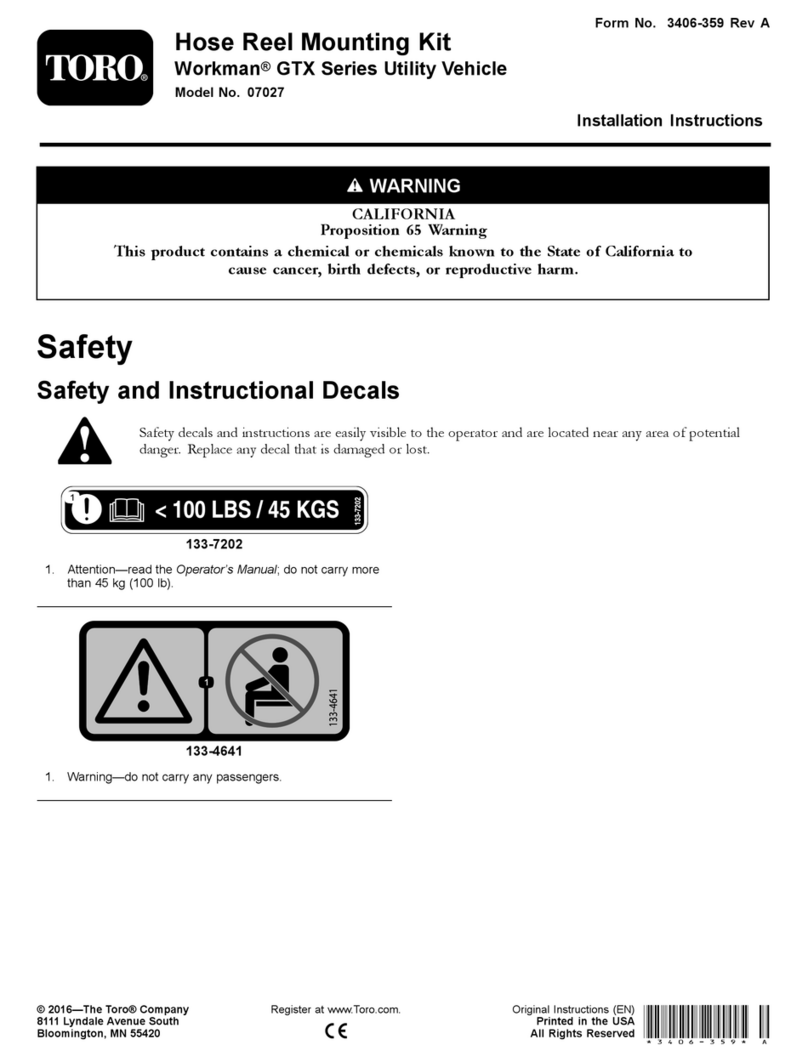
Toro 07419 User manual

FormNo.3457-578RevA
RearPTOKit
Heavy-DutyWorkman®Vehicles
ModelNo.07419
InstallationInstructions
Formachineswithserialnumbers239999999andbefore,decal93-9861isnotincludedinthekit.Youmust
purchasedecal93-9861separatelyandapplyit.
Safety
SafetyandInstructionalDecals
Safetydecalsandinstructionsareeasilyvisibletotheoperatorandarelocatednearanyarea
ofpotentialdanger.Replaceanydecalthatisdamagedormissing.
decal93-9861
93-9861
1.EngagePTO5.Entanglementhazard,
shaft
2.DisengagePTO6.ReadtheOperator's
Manual.
3.RearPTO7.Keepbystandersaway
fromthemachine.
4.Warning
decal93-9862
93–9862
1.Entanglementhazard—keepawayfrommovingparts;keep
allguardsandshieldsinplace.
©2022—TheToro®Company
8111LyndaleAvenueSouth
Bloomington,MN55420
Registeratwww.T oro.com.OriginalInstructions(EN)
PrintedintheUSA
AllRightsReserved*3457-578*

Installation
1
PreparingtheMachine
NoPartsRequired
Procedure
1.Parkthemachineonalevelsurface.
2.Formachinemodelswithautilitybed,perform
thefollowing:
A.Raisethebeduntiltheliftcylindersarefully
extended;refertotheOperator’sManual
forthemachine.
B.Removethebedsupportfromthestorage
bracketsonbackoftheROPSpanel(Figure
1).
g002397
Figure1
1.BedSupport
C.Pushthebedsupportontothecylinder
rod,makingsurethesupportendtabsrest
ontheendofcylinderbarrelandonthe
cylinderrodend(Figure2).
g009164
Figure2
1.Bedsupport3.Bed
2.Cylinderbarrel
3.Engagetheparkingbrake.
4.Shutofftheengineandremovethekey.
5.Disconnectthebatteryasfollows:
A.Squeezethebatterycovertoreleasethe
tabsfrombatterybase(Figure3).
g010326
Figure3
B.Removethebatterycoverfromthebattery
base(Figure3).
C.Removetheterminalofthepositivebattery
cablefromthebatterypost(Figure4).
Note:Ensurethattheterminalpositive
batterycabledoesnottouchthebattery
post.
2

g022071
Figure4
1.Terminalcover3.Batterypost
2.Positiveterminal4.Battery
2
InstallingthePTOControls
NoPartsRequired
InstallingtheLevers
Important:Usetheinstructionsinsteps1thru15
wheninstallingthekitonavehiclewithaserial
numbergreaterthan240000001;otherwiseskipto
ConnectingthePTOCable(page5).
1.Unscrewandremovealloftheknobsfromthe
consoleleversandfromthegearshiftlever
(Figure5).
g028744
Figure5
1.Consolelevers2.Gear-shiftlever
2.Removethe6screwsthatsecureoutsideedge
ofthecenterconsolecoverplatetotheframe
andremovethecoverplate(Figure6).
g028745
Figure6
1.Consolecoverplate3.Seat
2.Reservoirhose4.Shroud
3.Disconnectthereservoirhosefromtheradiator
andplugorclampthehosetoretainthecoolant
(Figure6).
4.Removethe8capscrewssecuringtheseats
andshroudtothemountingbrackets(Figure6).
Removeseatsandshroud.
5.Removethecotterpinsandclevispinsthat
securethecablestotheconsolelevers
(DifferentialLock,Hi–LowandHydraulicLift).
Retaincotterpinsandclevispins.
Note:Retainthecotterpinsandclevispins.
6.Removethenutandboltsecuringtheconsole
leverstoleverthesupportbracket(Figure7)
andtheremoveconsoleleverassemblyfrom
thelever-supportbracket.
3

g028746
Figure7
1.Nut3.Lever-supportbracket
2.Bolt4.Spacer
7.Removethespacer(Figure7)fromtheassembly
andinstallthenewPTOleverinit’splaceonthe
pivottube.
Note:PositiontheleverasshowninFigure8.
g028747
Figure8
1.PTOlever4.Pivottube
2.Flatwasher5.Spacer
3.Wavewasher
8.Installthepreviouslyremovedcomponentsonto
bolt,positioningeachasshowninFigure8.
9.Securethebolttotheleversupportbracketwith
thenutthatyouremovedpreviously(Figure8).
3
InstallingthePTOCable
NoPartsRequired
RoutingthePTOCable
1.RoutethePTOcableundertherearofthelever
supportbracket.
2.ConnectthePTOcableclevistotheholeinPTO
leverwithaclevispinandacotterpin(Figure9).
g028748
Figure9
1.PTOlever3.Clevispin
2.PTOcableclevis4.Cotterpin
3.SecurethePTOcabletoundersideofthelever
supportbracketwithaclampand2hex-socket
headself-tappingscrews(Figure10).
Note:ThePTOlevershouldbepositioned
soitisinlinewiththeHi–Lowlever(Engaged
position)whenthetransaxleisshiftedintothe
Lowposition.
4

g028749
Figure10
1.PTOcable3.Clamp
2.Leversupportbracket
4.Routethecable,alongtheexistingcables,and
tothecablebracketmountedatfrontleftcorner
ofthetransaxle(Figure11).
g028750
Figure11
1.PTOCable3.Jamnut
2.Cablebracket
5.LoosentherearjamnutsonthePTOcableand
inserttheendofcableintotheopeninginthe
bracket.LooselysecurethePTOcabletothe
bracketwiththejamnuts.
6.Installtheshroud,seats,consolecoverplate,
andleverknobsontothemachine;refertostep
2in2InstallingthePTOControls(page3).
Note:WhenthePTOisengaged,thelever
mustnotcontactthecenterconsoleplate.
ConnectingthePTOCable
Important:Accomplishtheinstallationstepsin
ConnectingthePTOCable(page5)onlywhen
installingthekitonamachinewithaserialnumber
priorto239999999;otherwiseskipto4Installing
thePTOtotheTransaxle(page6).
Note:Someofthepartsrequiredtoinstallthiskit
onmachineswithserialnumberspriorto239999999
arenotincludedinthekit,butarelistedintheparts
catalog.
1.Removealloftheknobsfromthecenterconsole
levers(Figure12).
g028751
Figure12
1.Centerconsolecover2.PTOlever(shown
installed)
2.Removethe6screwsthatsecuretheoutside
edgeofcenterconsolecoverplatetotheframe
andremovecoverplate(Figure12).
3.ConnectthePTOcableclevistothebottom
holeinPTOleverwithaclevispinandcotter
pin(Figure13)
5

g028752
Figure13
1.PTOlever4.PTOleversupport
2.PTOcable5.Self-tappingscrews
3.Clamp
4.SecurethePTOcabletothePTOleversupport
withaclampand2selftappingscrews(Figure
13).
5.InsertotherendofthePTOlevercablethrough
theopeninginrightsideoftheconsoleand
throughthecableholderintherearofthe
console(Figure14).
Note:Routethecable,alongtheexisting
cablestothecablebracketmountedatfrontleft
cornerofthetransaxle.
g028750
Figure14
1.PTOCable3.Jamnut
2.Cablebracket
6.Loosentherearjamnutsoncableandinsert
theendofcableintotheopeninginthebracket.
LooselysecurethePTOcabletothebracket
withthejamnuts.
7.Usingthe3selftappingscrewssuppliedinthe
kit,mountthePTOleversupporttotherightside
ofconsole.
Note:Theleverlocationisshowningure8.
8.Cleanconsoleplateandinstalltheoperation
decaltotheconsolenexttoPTOlever,locating
thedecalasshowninFigure15.
g028754
Figure15
1.Console2.Operationdecal
9.Installtheconsolecoverplateandthelever
knobstomachine.
Note:WhenthePTOisengaged,thelever
mustnotcontactthecenterconsoleplate.
4
InstallingthePTOtothe
Transaxle
NoPartsRequired
RemovingtheTransaxleCover
Plate
Note:Theremainingstepspertaintoinstalling
thekitonallvehiclesunlessotherwisespecied.
1.Disconnectthehydraulichosefromthettingon
transaxlecoverplate(Figure16).
Note:Capendofhosetopreventcontaminants
fromenteringhose.
6

g028755
Figure16
1.Transaxlecoverplate3.Fitting
2.Hydraulichose
2.Removethettingfromcoverplate.
3.InstallthettingintothefrontofthenewPTO
andpositionttingasshowninFigure17.
g028756
Figure17
1.PTO2.Fitting
4.Removethe5bolts,lockwashersandnut
thatsecurethecoverplatetothetransaxle
andcarefullyremovecoverplatetoprevent
damagingtheO–ringseal(Figure17).
Note:Retainfastenersforinstallationlater.
InstallingthePTO
1.Installthe2alignmentpinsintotheholesinthe
transaxle,atlocationsshowningure14.
2.Usingthemountingbolts,lockwashersandnut,
thatyouremovedfromthetransaxlecoverplate,
mountthePTOassemblyontotransaxle(Figure
18).
Note:WhenmountingthePTOassembly,make
surethatO-ringispositionedproperlyingroove
ontransaxle.IfO–ringisdamaged,replaceit.
g028757
Figure18
3.Removethecapfromthedisconnectedhydraulic
hoseandinstallthehosetottingonthePTO
withclampthatyoupreviouslyremoved.
Note:Makesurehoseandttingareclean
beforeconnectionismade.
4.MovethePTOleveratthecenterconsoleallthe
wayback(towardstherearoftheconsole)and
thePTOleverarm(Figure19)onthetransaxle
totherightside(passengerside).
g028758
Figure19
1.PTOleverarm3.PTOSwitchconnector
2.Cableclevis
5.Adjustthecableclevisorjamnutsorboththat
securethecabletothebracket,untiltheclevis
7

pinwilldropfreelythroughthealignedmounting
holesintheclevisandleverarm(Figure19).
6.Securetheclevispinwiththecotterpin,tighten
jamnutthatsecuresthecabletocableclevis,
andtightenthejamnutsthatsecurethecable
tothebracket.
7.Removethejumpercablefromthewireharness
locatedinfrontofPTO.
8.Routethewireharnessunderthepositive
batterycableandconnecttheconnectorofthe
wiringharnessintothePTOswitchconnector.
9.MountthePTOshieldtorearframetubewith4
capscrews,2spacers,and4locknuts(Figure
20).
g028759
Figure20
1.PTOShield
10.Applythewarningdecaltolower-rearcrosstube
nexttoexistingdecal,justabovehitchpoint
(Figure21).
g028760
Figure21
1.Rearcrosstube2.Warningdecal
11.Usingthe5cabletiessuppliedinkit,securethe
PTOcabletotheexistingwiring.
5
CompletingthePTO
Installation
NoPartsRequired
Procedure
1.Connectthebatterycablestothebatteryand
installthebatterycover;referto1Preparingthe
Machine(page2).
2.Testtheinterlocksystem;refertoCheckingthe
InterlockSystemintheOperator’sManual.
3.Shutofftheengineandinspectthemachinefor
hydraulicuidleakswherethePTOhousing
mountsontothetransaxle.
Note:Repairalluidleaks.
4.StarttheengineandoperatethePTO.
5.Removethecylinderlockfromthebed-lift
cylinderandstowitinthebracketsattheback
oftheROPSpanel;referto1Preparingthe
Machine(page2).
6.Lowerthebedandshutofftheengine.
8

Operation
WARNING
Thevehiclemaymoveunexpectedlyifthe
PTOisengagedandthevehicleisshiftedinto
gear,whichcouldresultinseriousinjuryto
abystander.
•Donotshiftthetransmissionintogearuntil
thePTOattachmenthasstoppedrotating,
eveniftheclutchisdepressed.
•Ensurethatnobystandersarenearthe
PTOoutputshaftorthefrontorrearof
vehicle.
DANGER
Anuncoveredrotatingsplinecancatch
clothingandresultinseriousinjuryordeath.
•Whenanattachmentisnotconnectedto
thePTOshaft,disengagethedrivetothe
PTObypullingbackonPTOlever.
•ThePTOincludesashield.Thisshield
mustremaininstalledonthevehicleandin
goodcondition.
•AlwaysdisengagethePTOandshutoffthe
enginebeforecouplinganyattachmentto
thePTOshaft.
CAUTION
Usingattachmentswithhighinertia(i.e.
mowersorblowers)willincreasetheamount
offorcerequiredtoshiftthevehicleandwill
damagethetransaxleiffrequentlyshifted.
•Donotshiftthevehiclewhilethevehicleis
movingifthePTOisengaged.
•Alwaysusetheoptionaloverrunningclutch
whenpoweringahigh-inertiaattachment
withthePTO.
DescriptionofOperation
ThePTOtakespowerfromtheengine,throughthe
transaxle,andsuppliespowerthroughastandard
540rpm-splinedshaftattherearofthevehicle.PTO
powercanbeusedforbothmobileandstationary
attachments.
Note:RefertoattachmentOperator’sManualforrpm
recommendations.
9

MobilePTOOperation
Important:WhenoperatingthePTO,themachine
mustnotbemovingwhenPTOisstarted.
1.Engagetheparkingbrake.
2.ShiftthetransmissionintotheNEUTRALposition.
3.Fullydepresstheclutchpedalandstartthe
engine.
Note:TheenginewillnotcrankunlessthePTO
leverisintheOFFposition.
4.ShiftthePTOleverasfollows:
Important:Donotengageordisengage
PTOwhilemovingotherwisedamagetothe
PTOwilloccur.Alwaysstopvehiclebefore
shiftingPTO.
•Formachineswithserialnumbers
239999999andbefore,movePTOlever
fullyforwardtotheENGAGEposition.
•Formachineswithserialnumbers
240000000andafter,movePTOleverfully
rearwardtotheENGAGEposition.
5.Shiftthetransmissionintothedesiredgear.
6.Disengagetheparkingbrake.
7.Slowlyreleasetheclutchpedal.
TostopthePTOoperation,fullydepresstheclutch
pedalandmovePTOlevertotheDISENGAGEposition.
Note:YoumaystopthePTOmomentarilybyfully
depressingtheclutchpedalandallowingmachineto
cometoacompletestop.
StationaryPTOOperation
Important:WhenoperatingthePTO,themachine
mustnotbemovingwhenPTOisstarted.
1.Engagetheparkingbrake.
2.ShiftthetransmissionintotheNEUTRALposition.
3.Fullydepresstheclutchpedalandstartthe
engine.
Note:TheenginewillnotcrankunlessthePTO
leverisintheDisengageposition.
4.ShiftthePTOleverasfollows:
Important:Donotengageordisengage
PTOwhilemovingotherwisedamagetothe
PTOwilloccur.Alwaysstopvehiclebefore
shiftingPTO.
•Formachineswithserialnumbers
239999999andbefore,movePTOlever
fullyforwardtotheENGAGEposition.
•Formachineswithserialnumbers
240000000andafter,movePTOleverfully
rearwardtotheENGAGEposition.
5.Slowlyreleasetheclutchpedal.
TostopthePTOoperation,fullydepressclutchpedal
andshiftPTOlevertotheDISENGAGEposition.
Note:YoumaystopthePTOmomentarilybyfully
depressingtheclutchpedalandallowingtransaxle
andPTOtocometoacompletestop.
10

DeclarationofIncorporation
ModelNo.SerialNo.ProductDescriptionInvoiceDescriptionGeneralDescriptionDirective
07419—RearPTOKit,Heavy-Duty
WorkmanVehiclesREARPTOKITUtilityVehicle2006/42/EC
RelevanttechnicaldocumentationhasbeencompiledasrequiredperPartBofAnnexVIIof2006/42/EC.
Wewillundertaketotransmit,inresponsetorequestsbynationalauthorities,relevantinformationonthispartly
completedmachinery.Themethodoftransmissionshallbeelectronictransmittal.
ThismachineryshallnotbeputintoserviceuntilincorporatedintoapprovedT oromodelsasindicatedonthe
associatedDeclarationofConformityandinaccordancewithallinstructions,wherebyitcanbedeclaredin
conformitywithallrelevantDirectives.
Certied:AuthorizedRepresentative:
MarcelDutrieux
ManagerEuropeanProductIntegrity
ToroEuropeNV
Nijverheidsstraat5
2260Oevel
Belgium
TomLangworthy
EngineeringDirector
8111LyndaleAve.South
Bloomington,MN55420,USA
October25,2022

UKDeclarationofIncorporation
ModelNo.SerialNo.ProductDescriptionInvoiceDescriptionGeneralDescriptionRegulation
07419—RearPTOKit,Heavy-Duty
WorkmanVehiclesREARPTOKITUtilityVehicleS.I.2008No.1597
RelevanttechnicaldocumentationhasbeencompiledasrequiredperSchedule10ofS.I.2008No.1597.
Wewillundertaketotransmit,inresponsetorequestsbynationalauthorities,relevantinformationonthispartly
completedmachinery.Themethodoftransmissionshallbeelectronictransmittal.
ThismachineryshallnotbeputintoserviceuntilincorporatedintoapprovedT oromodelsasindicatedonthe
associatedDeclarationofConformityandinaccordancewithallinstructions,wherebyitcanbedeclaredin
conformitywithallrelevantDirectives.
Thisdeclarationhasbeenissuedunderthesoleresponsibilityofthemanufacturer.
TheobjectofthedeclarationisinconformitywithrelevantUKlegislation.
AuthorizedRepresentative:
MarcelDutrieux
ManagerEuropeanProductIntegrity
ToroU.K.Limited
SpellbrookLaneWest
Bishop'sStortford
CM234BU
UnitedKingdom
TomLangworthy
EngineeringDirector
8111LyndaleAve.South
Bloomington,MN55420,USA
October25,2022
Table of contents
Other Toro Automobile Accessories manuals
Popular Automobile Accessories manuals by other brands

ULTIMATE SPEED
ULTIMATE SPEED 279746 Assembly and Safety Advice

SSV Works
SSV Works DF-F65 manual

ULTIMATE SPEED
ULTIMATE SPEED CARBON Assembly and Safety Advice

Witter
Witter F174 Fitting instructions

WeatherTech
WeatherTech No-Drill installation instructions

TAUBENREUTHER
TAUBENREUTHER 1-336050 Installation instruction
