Toro 34230 User manual

FormNo.3435-715RevA
Stand-OnE-Spreader/Sprayer
ModelNo.34230—SerialNo.400000000andUp
Registeratwww.Toro.com.
OriginalInstructions(EN)*3435-715*A

ItisaviolationofCaliforniaPublicResourceCode
Section4442or4443touseoroperatetheengineon
anyforest-covered,brush-covered,orgrass-covered
landunlesstheengineisequippedwithaspark
arrester,asdenedinSection4442,maintainedin
effectiveworkingorderortheengineisconstructed,
equipped,andmaintainedforthepreventionofre.
Theenclosedengineowner'smanualissupplied
forinformationregardingtheUSEnvironmental
ProtectionAgency(EPA)andtheCaliforniaEmission
ControlRegulationofemissionsystems,maintenance,
andwarranty.Replacementsmaybeorderedthrough
theenginemanufacturer.
WARNING
CALIFORNIA
Proposition65Warning
Theengineexhaustfromthisproduct
containschemicalsknowntotheStateof
Californiatocausecancer,birthdefects,
orotherreproductiveharm.
Batteryposts,terminals,andrelated
accessoriescontainleadandlead
compounds,chemicalsknownto
theStateofCaliforniatocause
cancerandreproductiveharm.Wash
handsafterhandling.
Useofthisproductmaycauseexposure
tochemicalsknowntotheStateof
Californiatocausecancer,birthdefects,
orotherreproductiveharm.
Introduction
Thisstand-onspreadersprayerisintendedforuse
bytrainedoperatorsinresidentialandcommercial
applications.Themachineisprimarilydesignedfor
chemicaldistributionusedforturfcareorsnow/ice
removalatresidentialgrounds,parks,sportselds,
andoncommercialgrounds.Usingthisproductfor
purposesotherthanitsintendedusecouldprove
dangeroustoyouandbystanders.
Readthisinformationcarefullytolearnhowtooperate
andmaintainyourproductproperlyandtoavoid
injuryandproductdamage.Youareresponsiblefor
operatingtheproductproperlyandsafely.
Visitwww.Toro.comforproductsafetyandoperation
trainingmaterials,accessoryinformation,helpnding
adealer,ortoregisteryourproduct.
Wheneveryouneedservice,genuineToroparts,or
additionalinformation,contactanAuthorizedService
DealerorT oroCustomerServiceandhavethemodel
andserialnumbersofyourproductready.Figure1
identiesthelocationofthemodelandserialnumbers
ontheproduct.Writethenumbersinthespace
provided.
Important:Withyourmobiledevice,youcan
scantheQRcode(ifequipped)ontheserial
numberplatetoaccesswarranty,parts,andother
productinformation.
g248806
Figure1
1.Modelandserialnumberlocation
ModelNo.
SerialNo.
©2019—TheToro®Company
8111LyndaleAvenueSouth
Bloomington,MN554202
Contactusatwww.Toro.com.
PrintedintheUSA
AllRightsReserved

Contents
Safety.......................................................................4
Safety-AlertSymbol............................................4
GeneralSafety...................................................4
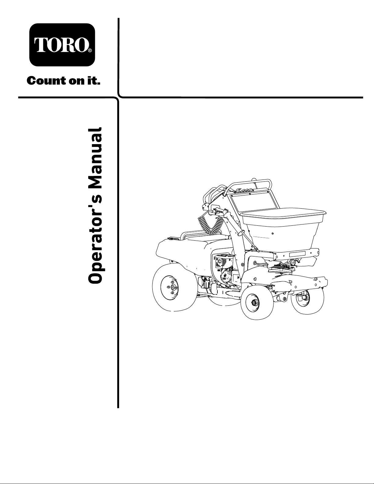
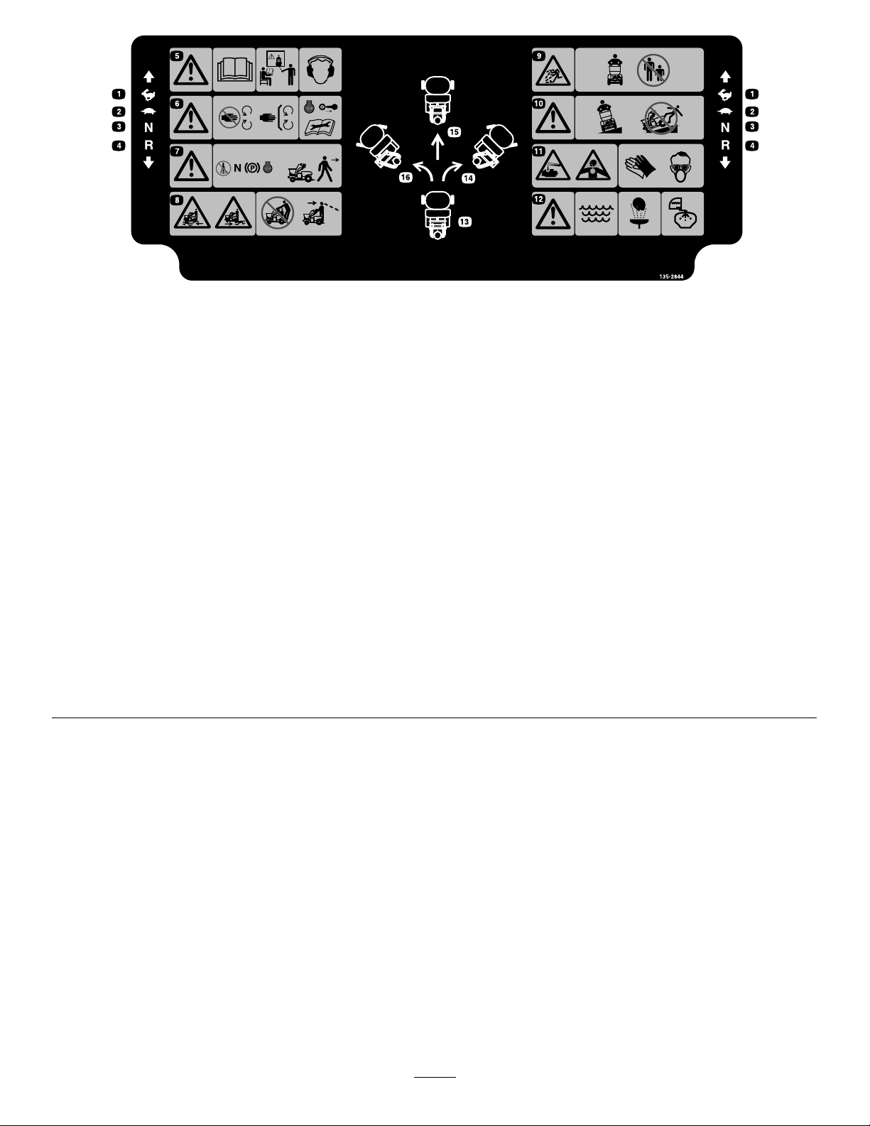
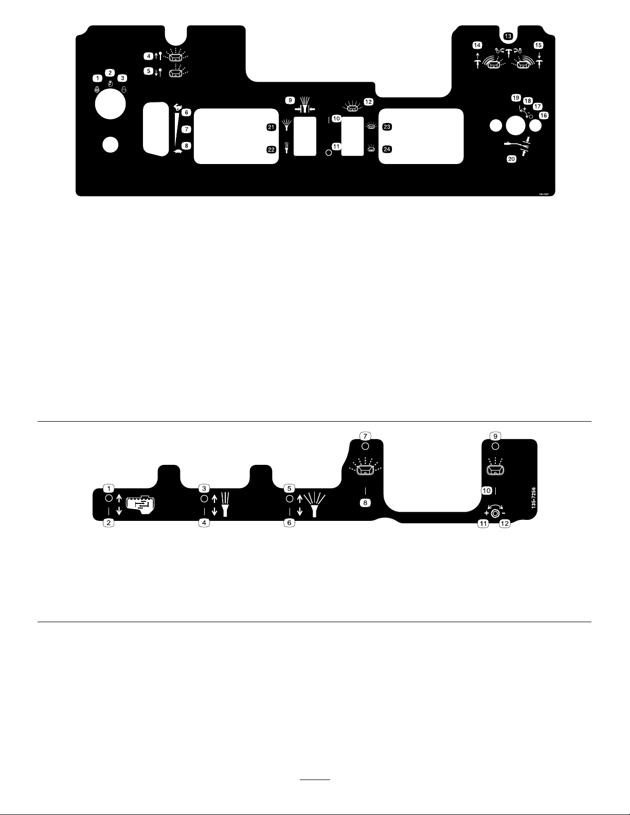
SafetyandInstructionalDecals..........................5
Setup........................................................................9
1CheckingtheTireAirPressure.........................9
2CheckingtheEngine-OilLevel.........................9
3CheckingtheTransaxle-FluidLevel.................9
4ConnectingtheBattery..................................10
ProductOverview...................................................10
Controls............................................................11
MachineControls...........................................11
EngineControls............................................12
SpreaderControls.........................................13
SprayerControls...........................................14
Specications..................................................16
BeforeOperation.................................................17
BeforeOperationSafety...................................17
PerformingDailyMaintenance..........................18
CheckingtheSafetyInterlockSystem...............18
FuelSpecication.............................................19
UsingStabilizer/Conditioner.............................19
FillingtheFuelTank..........................................19
DuringOperation.................................................20
DuringOperationSafety...................................20
OperatingtheMachine.....................................22
OperatingtheSpreader....................................25
OperatingtheSprayer......................................37
AfterOperation....................................................49
AfterOperationSafety......................................49
CleaningandLubricatingtheSpreader.............50
CleaningtheSprayer........................................51
TransportingtheMachine.................................53
Maintenance...........................................................55
MaintenanceSafety..........................................55
RecommendedMaintenanceSchedule(s)...........56
NotationforAreasofConcern...........................56
Pre-MaintenanceProcedures..............................57
PreparingtheMachine......................................57
Lubrication..........................................................57
LubricatingtheGreaseFittings.........................57
EngineMaintenance...........................................58
ServicingtheAirCleaner..................................58
EngineOilSpecication....................................58
CheckingtheEngine-OilLevel..........................59
ChangingtheEngineOil...................................59
ServicingtheSparkPlug...................................61
CleaningtheSparkArrester..............................61
FuelSystemMaintenance...................................62
DrainingtheFuelSystem..................................62
ElectricalSystemMaintenance...........................63
ServicingtheBattery.........................................63
RemovingandInstallingtheBattery..................65
Jump-StartingtheMachine...............................66
ServicingtheFuses..........................................67
DriveSystemMaintenance..................................68
CheckingtheAirPressureintheTires...............68
TorqueingtheAxleBoltsandLug
Nuts..............................................................68
AligningtheFrontWheels.................................68
ServicingtheTransaxle....................................70
ControlsSystemMaintenance.............................70
AdjustingthePatternControlCableforthe
Spreader.......................................................70
MaintainingtheChassis.......................................71
CheckingtheMachineforLoose
Hardware......................................................71
MaintainingtheSprayerSystem...........................72
CheckingSprayerSystem................................72
Cleaning..............................................................72
CleaningtheEngineandtheExhaust
SystemArea.................................................72
CleaningtheDebrisfromtheMachine...............72
RemovingtheEngineShroudandCleaning
theCoolingFins............................................72
WasteDisposal.................................................73
Storage...................................................................73
PreparingtheMachineforExtendedor
WinterStorage..............................................73
Troubleshooting......................................................75
SpreaderFaultCodes.......................................75
SprayerFaultCodes.........................................76
Schematics.............................................................82
3

Safety
ThefollowinginstructionsarefromANSIstandard
B71.4-2017.
Safety-AlertSymbol
Thesafety-alertsymbol(Figure2)isusedbothin
thismanualandonthemachinetoidentifyimportant
safetymessagesthatyoumustfollowtoavoidan
accident.
ThissymbolmeansAttention!BecomeAlert!Your
SafetyIsInvolved!
g000502
Figure2
Safety-alertsymbol
Thesafety-alertsymbolappearsaboveinformation
whichalertsyoutounsafeactionsorsituationsandis
followedbythewordDanger,Warning,orCaution.
Dangerindicatesanimminentlyhazardoussituation
which,ifnotavoided,willresultindeathorserious
injury.
Warningindicatesapotentiallyhazardoussituation
which,ifnotavoided,couldresultindeathorserious
injury.
Cautionindicatesapotentiallyhazardoussituation
which,ifnotavoided,mayresultinminorormoderate
injury.
Thismanualuses2otherwordstohighlight
information.Importantcallsattentiontospecial
mechanicalinformationandNoteemphasizesgeneral
informationworthyofspecialattention.
GeneralSafety
Thismachineiscapableofamputatinghandsandfeet
andofthrowingobjects.T orodesignedandtestedthis
machinetoofferreasonablysafeservice;however,
failuretocomplywithsafetyinstructionsmayresultin
injuryordeath.
•Read,understand,andfollowallinstructionsand
warningsintheOperator’sManualandother
trainingmaterials,onthemachine,theengine,and
attachments.Alloperatorsandmechanicsshould
betrained.Iftheoperator(s)ormechanic(s)cannot
readthismanual,itistheowner’sresponsibilityto
explainthismaterialtothem;otherlanguagesmay
beavailableonourwebsite.
•Onlyallowtrained,responsible,andphysically
capableoperatorswhoarefamiliarwiththesafe
operation,operatorcontrols,andsafetysignsand
instructionstooperatethemachine.Neverallow
childrenoruntrainedpeopleoperateorservicethe
equipment.Localregulationsmayrestricttheage
oftheoperator.
•Alwaysuseappropriatepersonalprotective
equipment(PPE)toguardagainstcontactwith
chemicals.
•Donotoperatethemachineneardrop-offs,
ditches,embankments,water,orotherhazards.
•Donotputyourhandsorfeetnearmoving
componentsofthemachine.
•Neveroperatethemachinewithdamagedguards,
shields,orcovers.Alwayshavesafetyshields,
guards,switchesandotherdevicesinplaceandin
properworkingcondition.
•Stopthemachine,shutofftheengine,andremove
thekeybeforeservicing,fueling,orunclogging
themachine.
4

SafetyandInstructionalDecals
•Keepallsafetysignslegible.Removeallgrease,
dirt,anddebrisfromsafetysignsandinstructional
labels.
•Replaceallworn,damaged,ormissingsafety
signs.
•Whenyouinstallreplacementcomponents,ensure
thatcurrentsafetysignsareafxedtothose
components.
•Ifyouhaveinstalledanattachmentoraccessory,
ensurethatcurrentsafetysignsarevisible.
•Familiarizeyourselfwiththefollowingsafetysigns
andinstructionlabels.Theyarecriticaltothesafe
operationofyourmachine.
decal133-8062
133-8062
decal126-2620
126-2620
1.Pullleveruptodisengage
thebrake.
2.Pushleverdownto
engagethebrake.
decal135-6949
135-6949
1.MainFuse,20A3.Startrelay
2.Regulator,20A4.GND-ShutdownRelay
decal126-2621
126-2621
1.Unlocktopushmachine.3.Locktodrivemachine.
2.Readtheinstructions
beforeservicingor
performingmaintenance.
decal126-4994
126-4994
1.Cutting/dismembermenthazard—keepawayfrommoving
parts.
2.Warning—donotusetheupperfrontlocationsastiedown
points,onlyusethespeciedtie-downpoints;seethe
Operator’sManualforlocation.
5

decal126-5186
126-5186
1.ReadtheOperator'sManualbeforeservicingthemachine
orperformingmaintenance.
4.Formoreinformationonservicingtherearaxleshafts,read
theOperator'sManual.
2.Greasethesteeringpivotsevery100hours.5.Checkthetirepressure—90kPa(13psi)every50hours.
3.Checkthehydraulicuidlevelevery50hours.6.ReadtheOperator'sManual.
6

decal135-2844
135-2844
1.Fast
2.Slow
3.Neutral
4.Reverse
5.Warning-ReadtheOperator’sManual.Donotoperatethismachineunlessyouaretrained.Wearhearingprotection.
6.Warning-Stayawayfrommovingparts;keepallguardsinplace.Stopengineandremovekeybeforeadjusting,servicing,
orcleaning.
7.Warning-Disengagesprayercontrols,movedrivelevertoneutralposition,engageparkingbrake,andstopenginebeforeleaving
theoperator’sposition.
8.Crushing/dismembermenthazardofbystanders-DoNotcarrypassengers,lookforwardanddownwhenoperatingthemachine,
lookbehindanddownwhenreversing.
9.Thrownobjecthazard-DoNotoperatewhenpeopleandpetsareinthearea.
10.Warning-operateacrossslopesnotupanddown.Loadsmayshiftonslopesorwhenturning.DoNotoperateonwetslopes–use
extremecautionwhenoperatingonslopes.
11.Causticliquid/chemicalburnandtoxicgasinhalationhazards-wearhand,skin,eye,andrespiratoryprotection.
12.Warning-Usefresh,cleanwater:
-forrst-aidwashing
-forrinsingthetank.
13.Neutral
14.Movethesteeringcontrolrighttoturnright.
15.Movethesteeringcontroltothecentertogostraight.
16.Movethesteeringcontrollefttoturnleft.
7

decal135-7247
135-7247
1.Engine-Off13.Spreaderpatterncontrol-rotatecounterclockwisetounlock;
rotateclockwisetolock.
2.Engine-On14.Spreadpatterncontrol-pullhandleupifheavyonleftside.
3.Engine-Start15.Spreadpatterncontrol-pushhandledownifheavyonright
side.
4.Deector-Pullknobuptoopen16.Spraywandpressurecontrol-Off
5.Deector-Pushknobdowntoclose17.Spraywandpressurecontrol-Decrease
6.Throttle-Fast18.Spraywandpressurecontrol-Increase
7.Continuousvariablesetting19.Spraywandpressurecontrol-On
8.Throttle-Slow20.Spraywandpressurecontrol
9.Spraypressurecontrol21.Increasepressure
10.On22.Decreasepressure
11.Off23.Increasespreadpattern
12.Granularspinnercontrol24.Decreasespreadpattern
decal135-7256
135-7256
1.Agitation—Off5.Widespray—Off9.Narrowspreader—Off
2.Agitation—On6.Widespray—On10.Narrowspreader—On
3.Narrowspray—Off7.Widespreader—Off11.Narrowspreaderow—increase
4.Narrowspray—On8.Widespreader—On12.Narrowspreaderow—decrease
8

Setup
LooseParts
Usethechartbelowtoverifythatallpartshavebeenshipped.
ProcedureDescriptionQty.Use
4Nopartsrequired–Connectthebattery.
MediaandAdditionalParts
DescriptionQty.Use
Operator'sManual1Readbeforeoperatingthemachine.
Key2Startthemachine.
1
CheckingtheTireAir
Pressure
NoPartsRequired
Procedure
Checktheairpressureinthefrontandreartires,and
ifnecessary,addairtotheappropriatepressure;refer
toCheckingtheAirPressureintheTires(page68).
2
CheckingtheEngine-Oil
Level
NoPartsRequired
Procedure
Theenginecomeswithoil;checktheengine-oillevel
and,ifnecessary,addtotheappropriatelevel;referto
EngineOilSpecication(page58)andCheckingthe
Engine-OilLevel(page59).
3
Checkingthe
Transaxle-FluidLevel
NoPartsRequired
Procedure
Thetransaxlecomeswithuid;checktransaxle-uid
levelintheexpansiontank,andifnecessary,addto
theappropriatelevel;refertoServicingtheTransaxle
(page70).
9

4
ConnectingtheBattery
NoPartsRequired
Procedure
1.Removethebatterycoverfromthebatterybox
(Figure3).
g027115
Figure3
1.Batterybox5.Batterycover
2.Batterysupport6.Negativeterminal
3.Buckle7.Positiveterminal
4.Batterystrap
2.Installthepositivebatterycabletothepositive
(+)batteryterminalwithaangedboltand
angednut(Figure3).
3.Installthenegativebatterycabletothenegative
(–)batteryterminalwithaangedboltand
angednut(Figure3).
4.Installthecoveronthebatteryboxandsecure
thecoverandboxtothebatterytraywiththe
batterystrap(Figure3).
ProductOverview
g304841
Figure4
1.Motion/steeringcontrol5.Hopper
2.Engine/spreader—sprayer
controls
6.Impeller
3.Spraywand7.Sprayernozzles
4.Hoppercover
g304840
Figure5
1.Fuel-tankcap3.Sprayer-tankcap
2.Battery4.Platform
10

Controls
MachineControls
g304845
Figure6
1.Controlconsole5.Frontreferencebar
2.Steeringcontrol6.Reverse
3.Rearreferencebar7.Forward
4.Motion-controllever
(Neutralposition)
SteeringControl
Thesteeringcontrolislocatedbehindthecontrol
console(seeFigure6).
•Movethesteeringcontroltotherightorleftto
steerthemachinetotherightorleftrespectively.
•Movingthesteeringcontroltothecenterallows
themachinetosteerstraight.
Motion-ControlLever
Themotion-controllever,locatedinthecenterofthe
steeringcontrol,controlstheforwardandreverse
motionofthemachine(seeFigure6).
•Movethemotion-controlleverforwardorbackward
todrivethemachinerespectively.
Note:Themachinespeedisproportionaltothe
amountthatyoumovethemotion-controllever.
•Whenyoumovethemotion-controllevertothe
centerposition,themachineshouldstop.
Note:Whenyoureleasethemotion-controllever,
itshouldreturntotheNEUTRALposition.
Important:Ifthemotion-controlleverdoes
notreturntotheNEUTRALpositionwhenyou
releaseit,contactanAuthorizedService
Dealer.
Parking-BrakeLever
Theparking-brakeleverislocatedabovetheplatform
ontherightside(Figure7).
•Toengagetheparkingbrake,pushthe
parking-brakeleverdown.
Note:Thebrakeleverengagesaparkingbrake
inthetransaxle.
•Toreleasetheparkingbrake,pulltheleverup.
g025162
Figure7
1.Drive-wheel-releaselever3.Park-brakelever
2.Platform
Note:Whenparkingonasteepslope,chockorblock
thewheelsinadditiontoengagingtheparkingbrake.
Whentransportingthemachine,engagetheparking
brakeandbindthemachinetothetransportvehicle.
Drive-Wheel-ReleaseLever
Thedrive-wheel-releaseleverislocatedabovethe
platformontheleftside(Figure7).
Usethedrive-wheel-releaselevertodisengagethe
hydrostatic-drivesystemtomovethemachineby
hand.
•Topushorpullthemachine,movethe
drive-wheel-releaseleverup.
•Tooperatethemachine,movethe
drive-wheel-releaseleverdown.
11

EngineControls
g304856
Figure8
1.Ignitionswitch3.Throttle
2.Choke4.Enginehourmeter
(sprayerandinformation
display)
IgnitionSwitch
Theignitionswitchislocatedattheleftsideofthe
controlconsole(Figure8).
Usetheignitionswitchtostartandrun,orshutoffthe
engine.Theignitionswitchhas3positions:STOP,
RUNandSTART.
Note:Youmustengagetheparkingbraketostart
theengine.
ChokeControl
Thechokecontrolislocatedattheleftsideofthe
controlconsole;youuseittohelpstartacoldengine
(Figure8).
Note:Donotstartorrunawarmenginewiththe
chokeintheONposition.
•Pulluponthechokecontroltosetthechoketo
theONposition.
•Pushdownonthechokecontroltosetthechoke
totheOFFposition.
ThrottleControl
Thethrottlecontrol(theredlever)islocatedattheleft
sideofthecontrolconsole(Figure8).
HourMeter(SprayerandInformationDisplay)
Thehourmeterdisplaysinthesprayerandinformation
displayislocatedtotherightofthethrottle,atthe
bottomofthecontrolconsole(Figure8).
Thehourmeterrecordsthenumberofhoursthatthe
machinehasoperated.Hourmetertimedisplays
whenthekeyisintherunpositionandthesprayer
controlswitchisshutoff.
Fuel-ShutoffValve
Thefuel-shutoffvalveislocatedatthefront,rightside
oftheenginebelowthefueltank(Figure9).
Note:Closethefuel-shutoffvalvewhenyoudonot
usethemachineforafewdays,transportthemachine
toandfromthejobsite,orparkthemachineinsidea
building.
g248833
Figure9
1.Fuel-shutoffvalve(rightsideoftheengine)
12

SpreaderControls
g304859
Figure10
1.Deector-gatecontrol5.Spreader-patterncontrol
2.Heavydistribution
granular-gatelever
6.Impellercontrolswitch
3.Lightdistribution
granular-gatelever
7.Spreaderandinformation
display
4.Flow-rateadjustment
knob—lightdistribution
granulargate
DeectorGateControl
Thedeector-gatecontrolislocatedtotheabovethe
throttleonthecontrolconsole(Figure10).
Usethedeector-gatecontroltotemporarilystop
thedischargeofgranularmaterialsattheleftside
ofthespreader.Closethedeectorgatewiththe
controlwhenitisnotdesirabletobroadcastgranular
materialsontosidewalks,parkinglots,orpatios.
•Pushtheknobforthedeector-gatecontroldown
toclosethegateandtemporarilydeectthe
granularmaterials.
•Pulltheknobuptoopenthedeectorgateforfull
granularbroadcasting.
HeavyDistributionGranular-GateLever
Theheavydistributiongranular-gateleveristhefourth
leverlocatedatthetopcenterofthecontrolconsole
(Figure10).
•Tobroadcastawidepatternofgranularmaterial,
pulltheheavydistributiongranular-gatelever
rearwardtothefullopenposition.
•Toclosetheimpellergate,pushtheheavy
distributiongranular-gateleverforwardfullclosed
position.
LightDistributionGranular-GateLever
Thelightdistributiongranular-gateleveristhefth
leverlocatedatthetopcenterofthecontrolconsole
(Figure10).
•Tobroadcastanarrowpatternofgranularmaterial,
pullthelightdistributiongranular-gatelever
rearwardfullytothelimitedOPENposition.
•Toclosetheimpellergate,pushtheheavy
distributiongranular-gateleverforwardfully.
Note:Onlytheheavydistributiongranular-gate
leverclosestheimpellergate.Pushingtheheavy
distributiongranular-gateleverforwardalsoresets
thelightdistributiongranular-gatelevertothe
forwardposition.
Spreader-PatternControl
Thespreader-patterncontrolislocatedtotheright
ofthedeector-gatecontrolatthecontrolconsole
(Figure10).
Usethespreader-patterncontroltobroadcasta
heavierpatternofgranularmaterialtotheleftorright
sideofthemachine.
•Tobroadcastaheavierpatterntotheleft,unlock
thespreader-patterncontrol,pullthecontrolup
slightly,andlockthecontrol.
•Tobroadcastaheavierpatterntotheright,unlock
thespreader-patterncontrol,pushthecontrol
downslightly,andlockthecontrol.
Flow-RateAdjustmentKnob—lightDistribution
GranularGate
Theow-rateadjustmentknobislocatedbelowthe
heavydistribution-andlightdistributionimpeller-gate
levers(Figure10).
Usetheow-rateadjustmentknobtocontrol
thedischargerateofgranularmaterialfromthe
hopperontotheimpellerwhenthelightdistribution
granular-gateleverisintheOPENposition(limited).
•Rotatethenarrow-spreaderdistribution-ow-rate
knobclockwisetodecreasethedischargerateof
granularmaterialfromthehopper.
•Rotatethedistributionow-rate-knob
counterclockwisetoincreasethedischargerateof
granularmaterialfromthehopper.
ImpellerControlSwitch
Theimpellercontrolswitchislocatedtotheleftofthe
Impeller-speeddisplay,atthebottomofthecontrol
console(Figure10).
Usetheimpellercontrolswitchtoruntheelectric
motorthatdrivestheimpeller.
13

SpreaderandInformationDisplay
Thespreaderandinformationdisplayislocatedbelow
thedistributionimpeller-gateleversatthebottomof
thecontrolconsole(Figure10).
Thespreaderandinformationdisplayshowsthe
followinginformation:
•Thespreadercontrollerrmwareversion
•Anhourmeterforthespreader-impellermotor
•Thespeedoftheimpellermotorasapercentof
motor-rotationspeed
•Faultcodes
Drop-rateCamandLinkage
Thedrop-ratecamandlinkagearelocatedatthefront
ofthemachineandbelowthehopperonthespreader
(Figure11).
g027033
Figure11
1.Slot–maximumposition2.Linkage
Usethedrop-ratecamtosetthemaximumamountof
materialtobedispensedthroughtheimpellergate
andontotheimpeller.
Theslotinthecam,aftersetting9onthecam,
allowsyoutoopentheimpellergatetothemaximum
position.Youcanusethissettingfordrysand,ice
melt,orothermaterialsthataredifculttospread.
Note:Usecamsetting9maywhenyouarecleaning
outthehopper.
SprayerControls
g304858
Figure12
1.Tank-agitationlever5.Sprayerandinformation
display
2.Narrow-spraypatternlever6.Sprayer-pumpswitch
3.Wide-spraypatternlever7.Spray-wandpressure
control
4.Sprayerwand
Tank-AgitationLever
Thetank-agitationleverislocatedonthecontrol
console(Figure12).
Settingthetank-agitationlevertotheONposition
allowsthesprayerpumptocirculatethecontentinthe
spraytanktokeepthechemicalsolutionmixed.
•Pullthetank-agitationlevertocirculatethecontent
inthespraytank.
•Pushthelevertostopcirculatingthecontentin
thespraytank.
Note:Donotuseagitationwhilespraying.Shut
offthetankagitationtoensureproperspray
distribution.
Note:Runtheenginespeedaboveidleandrunthe
sprayerpumpforthetankagitationtoworkeffectively.
Narrow-SprayPatternLever
Thenarrow-spraypatternleverislocatedonthe
controlconsole(Figure12).
•ToturnONthesprayerinanarrow-spraypattern
(thecenternozzleonly),pullthenarrow-spray
patternlevertowardyou.
•ToturnOFFthesprayer,pushthenarrow-spray
patternleverawayfromyou.
14

Wide-SprayPatternLever
Thewide-spraypatternleverislocatedonthecontrol
console(Figure12).
•ToturnONthesprayerinawide-spraypattern(the
rightandleftnozzles),pullthewide-spraypattern
levertowardyou.
•ToturnOFFthesprayer,pushthewide-spray
patternleverawayfromyou.
Spray-WandTriggerandTriggerLock
Thespray-wandtriggerandtriggerlockarelocated
onthebottomofthespray-wandhandle(Figure12
andFigure13).
•Tousethespraywand,holdthehandleofthe
wandsqueezethetrigger.
•TolockthetriggertotheONposition,fullysqueeze
thetriggeragainstthehandleandthenlatchthe
triggerlockoverthetrigger;tounlockthetrigger,
unlatchthetriggerlockfromthetrigger.
•Releasethetriggertostopthespray.
g304906
Figure13
1.Triggerlock3.Trigger
2.Spray-wandhandle
SprayerandInformationDisplay
Thesprayerandinformationdisplayislocatedto
therightofthethrottle,atthebottomofthecontrol
console(Figure12).
Thesprayerandinformationdisplayshowsthe
followinginformation:
•Sprayercontrollerrmwareversion
•Hourmeterfortheengine
•Hourmeterforthesprayer-pumpmotor
•Batteryvoltage
•Spray-systempressure
•Faultcodes
Sprayer-PumpSwitch
Thesprayer-pumpswitchislocatedtotheleftofthe
hourmeterandspraypressuredisplay,onthecontrol
console(Figure12).
Usethesprayer-pumpswitchtostarttheelectric
motorthatdrivesthesprayerpumpandrecirculation
pump,adjustthesprayersystempressure,andshut
offsprayerpumpandrecirculationpumpmotors.
Spray-WandPressureControl
Thespray-wandpressurecontrolislocatedtothe
rightoftheimpeller-speeddisplay,attherightsideof
thecontrolconsole(Figure12).
Usethespray-wandpressurecontrolthespray-system
pressureatthespraywand.
TankDrainValve
Thetankdrainvalveislocatedattheleftsideand
underthesprayertank(Figure15).
Usethetankdrainvalvetoemptythesprayertank
ofliquidchemicals.
g027226
Figure14
1.Handle(openposition)3.Sprayertank
2.Tankdrainvalve
•Toopenthevalve,rotatethehandleofthetank
drainvalve90°clockwise(leverin-linewithvalve).
•Toclosethevalve,rotatethehandle90°
counterclockwise.
Sprayer-Pump-SupplyValve
Thesprayer-pump-supplyvalveislocatedatthe
rightsideofthemachineandunderthesprayertank
(Figure15).
15

Usethesprayer-pump-supplyvalvetoshutoffthe
owofliquidchemicalstothepump.
g259738
Figure15
1.Sprayertank3.Handle(openposition)
2.Sprayer-pump-supply
valve
•Toopenthevalve,rotatethehandlevalve90°
clockwise(leverin-linewithvalve).
•Toclosethevalve,rotatethehandle90°
counterclockwise.
Specications
Overallwidth90cm(35.5
inches)
Overalllength171cm(67.5
inches)
Overallheight131cm(51.5
inches)
Weightsprayertankand
hopperempty
227kg(500lb)
onlyhopperfull307kg(676lb)
onlysprayertank
full
309kg(682lb)
sprayertankand
hopperemptyand
1extrabagof
granularmaterial
inthetank
412kg(909lb)
Maximum
machineweight
loadedmachine+
operator
≤513kg(1130lb)
Hoppercapacity79kg(175lb)
SpreaderCast1.2m(4ft)
through6.7(22
ft)
Sprayertank
capacity
76L(20US
gallon)
Narrowpattern1.5m(5ft)
MaximumSpray
WidthWidepattern3.4m(11ft)
Maximumground
speed
forward9kph(5.5mph)
16

Operation
Note:Determinetheleftandrightsidesofthe
machinefromthenormaloperatingposition.
BeforeOperation
BeforeOperationSafety
GeneralSafety
•Evaluatetheterraintodeterminewhataccessories
andattachmentsareneededtoproperlyand
safelyperformthejob.Useonlyaccessoriesand
attachmentsapprovedbyToro.
•Inspecttheareawhereyouwillusetheequipment,
andremoveallrocks,toys,sticks,wires,
bones,andotherforeignobjectsthatmaybe
contaminatedbychemicalsand/oraffectthe
stabilityofthemachine.
•Wearappropriateclothing,includingsafety
glasses,substantialslip-resistantfootwear,and
hearingprotection.Tiebacklonghairandavoid
looseclothingorjewelrythatmaygettangledin
movingparts.
•Donotoperatethemachinewhilepeople,
especiallychildren,orpetsareinthearea.Stop
themachineandtheattachment(s)ifanyone
entersthearea.
•Donotll,calibrate,orcleanthemachinewhile
people,especiallychildren,orpetsareinthearea.
•Checkallsprayercomponentsforwearandleaks
beforeapplyingpressuretothesystem.Donot
usethemachineifitisleakingordamaged.
•Ensurethattheoperatorplatformiscleanandfree
fromchemicalresidueanddebrisbuildup.
•Checkthattheoperator-presencecontrols,safety
switches,andshieldsareattachedandfunctioning
properly.Donotoperatethemachineunlessthey
arefunctioningproperly.Frequentlycheckfor
wornordeterioratingcomponentsandreplace
themwiththemanufacturer’srecommendedparts
whennecessary.
ChemicalSafety
Chemicalsubstancesusedinthespreader-sprayer
systemmaybehazardousandtoxictoyou,
bystanders,animals,plants,soilsorotherproperty.
•Carefullyreadandfollowthechemicalwarning
labelsandSafetyDataSheets(SDS)forall
chemicalsusedandprotectyourselfaccordingto
thechemicalmanufacturer'srecommendations.
Ensurethataslittleskinaspossibleisexposed
whileusingchemicals.Useappropriatepersonal
protectiveequipment(PPE)toguardagainst
personalcontactwithchemicals,suchasthe
following:
–safetyglasses,goggles,and/orfaceshield
–chemical-resistantgloves
–rubberbootsorothersubstantialfootwear
–hearingprotection
–respiratororltermask
–cleanchangeofclothes,soap,anddisposable
towels,tobekepton-handintheeventofa
chemicalspill
•Ifyouareusingmorethan1chemical,readthe
informationabouteachchemical.Refuseto
operateorworkonthespreader-sprayerifthis
informationisnotavailable.
•Beforeworkingonaspreader-sprayersystem,
ensurethatthesystemhasbeentriplerinsedand
neutralizedaccordingtotherecommendations
ofthechemicalmanufacturer(s)andthatallthe
valveshavebeencycledthreetimes.
•Verifythereisanadequatesupplyofcleanwater
andsoapnearby,andimmediatelywashoffany
chemicalsthatcontactyou.
•Obtainpropertrainingbeforeusingorhandling
chemicals.
•Usethecorrectchemicalforthejob.
•Followthechemicalmanufacturer'sinstructions
forthesafeapplicationofthechemicalanddo
notexceedtherecommendedsystemapplication
pressure.
•Handlechemicalsinawell-ventilatedarea.
•Havecleanwateravailable,especiallywhenlling
thespraytank.
•Donoteat,drink,orsmokewhileworkingwith
chemicals.
•Donotcleanspraynozzlesbyblowingthrough
themorplacingtheminyourmouth.
•Alwayswashyourhandsandotherexposedareas
assoonaspossibleafternishingthework.
•Keepchemicalsintheiroriginalpackagesandina
safelocation.
•Properlydisposeofunusedchemicalsand
chemicalcontainersasinstructedbythechemical
manufacturerandyourlocalcodes.
•Chemicalsandfumesaredangerous;neverenter
thetankorhopper,anddonotplaceyourhead
overorintheopening.
•Followalllocal,state,andfederalrequirementsfor
spreadingandsprayingchemicals.
17

FuelSafety
Useextremecarewhenhandlingfuel.
Incertainconditionsgasolineisextremelyammable
anditsvaporsareexplosive.Areorexplosionfrom
gasolinecanburnyou,others,andcauseproperty
damage.
•Fillthefueltankoutdoorsonlevelground,inan
openarea,whentheengineiscold.Wipeupany
gasolinethatspills.
•Neverrellthefueltankordrainthemachine
indoorsorinsideanenclosedtrailer.
•Donotllthefueltankcompletelyfull.Fillthefuel
tanktothebottomofthellerneck.Theempty
spaceinthetankallowsthegasolinetoexpand.
•Neversmokewhenhandlinggasoline,andstay
awayfromanopenameorwheregasolinefumes
maybeignitedbyaspark.
•Storegasolineinanapprovedcontainerandkeep
itoutofthereachofchildren.
•Addfuelbeforestartingtheengine.Neverremove
thecapofthefueltankoraddfuelwhenengineis
runningorwhentheengineishot.
•Ifyouspillfuel,donotattempttostarttheengine.
Moveawayfromtheareaofthespillandavoid
creatinganysourceofignitionuntilthefuelvapors
havedissipated.
•Donotoperatethemachinewithouttheentire
exhaustsysteminplaceandinproperworking
condition.
•Incertainconditionsduringfueling,staticelectricity
canbereleased,causingaspark,whichcanignite
gasolinevapors.Areorexplosionfromgasoline
canburnyouandothersandcauseproperty
damage.
–Alwaysplacegasolinecontainersonthe
groundawayfromyourvehiclebeforelling.
–Donotllgasolinecontainersinsideavehicle
oronatruckortrailerbed,becauseinterior
carpetsorplastictruckbedlinersmayinsulate
thecontainerandslowthelossofanystatic
charge.
–Whenpractical,removegasoline-powered
equipmentfromthetruckortrailerandrefuel
theequipmentwithitswheelsontheground.
–Ifthisisnotpossible,thenrefuelsuch
equipmentonatruckortrailerfromaportable
containerratherthanfromagasoline-dispenser
nozzle.
–Ifyoumustuseagasoline-dispensernozzle,
keepthenozzleincontactwiththerimofthe
fueltankorcontaineropeningatalltimes
untilfuelingiscomplete.Donotuseanozzle
lock-opendevice.
•Gasolineisharmfulorfatalifswallowed.
Long-termexposuretovaporshascausedcancer
inlaboratoryanimals.Failuretousecautionmay
causeseriousinjuryorillness.
–Avoidprolongedbreathingofvapors.
–Keepyourfaceawayfromthenozzleand
gasolinetankorcontaineropening.
–Keepgasolineawayfromyoureyesandskin.
–Neversiphongasolinebymouth.
•Tohelppreventres,dothefollowing:
–Keeptheengineandtheengineareafree
fromaccumulationofgrass,leaves,excessive
greaseoroil,andotherdebristhatcan
accumulateintheseareas.
–Cleanupoilandfuelspillsandremove
fuel-soakeddebris.
–Allowthemachinetocoolbeforestoringthe
machineinanyenclosure.Donotstorethe
machinenearaameoranyenclosedarea
whereopenpilotlightsorheatappliancesare
present.
PerformingDaily
Maintenance
Beforestartingthemachineeachday,performthe
followingdaily-checkprocedures:
•CheckingtheEngine-OilLevel(page59)
•CheckingtheSafetyInterlockSystem(page18)
•CheckingtheMachineforLooseHardware(page
71)
CheckingtheSafety
InterlockSystem
ServiceInterval:Beforeeachuseordaily
CAUTION
Ifinterlockswitchisdisconnectedordamaged
themachinecouldoperateunexpectedly
causingpersonalinjury.
•Donottamperwiththeinterlockswitch.
•Checktheoperationoftheinterlockswitch
dailyandreplacedamagedswitchbefore
operatingthemachine.
Important:Ensurethatthesafetymechanisms
onyourmachineareconnectedandinproper
operatingconditionpriortooperatingyour
machine.
18

Thesafetyinterlocksystemisdesignedtopreventthe
enginefromstartingunlessyouengagetheparking
brake.
TestingtheStarterInterlock
ServiceInterval:Beforeeachuseordaily
1.Movethemachinetoalevelsurface.
2.Chockthewheelsofthemachine.
3.Disconnectthespark-plugwires.
4.Releasetheparkingbrake.
5.Withthemotion-controlleverintheNEUTRAL
positionturnthekeytotheSTARTposition.
Note:Thestartermustnotrotatetheengine.
•Ifthestarterrotatestheengineofyour
machine—themachinedoesnotpass
thistest,donotoperateit.Contactyour
authorizedT orodistributor.
•Ifthestarterdoesnotrotatetheengine—the
machinedoespassthetest:engagethe
parkingbrake,connectthespark-plugwire
tothesparkplug,andremovethechock(s)
fromthewheels.
FuelSpecication
Petroleum
fuel
Useunleadedgasolinewithanoctaneratingof87
orhigher((R+M)/2ratingmethod).
Useanunleaded-gasolineblendwithupto10%
ethanol(gasohol)or15%MTBE(methyltertiary
butylether)byvolumeisacceptable.Ethanoland
MTBEarenotthesame.
Ethanol
blended
fuel
Gasolinewith15%ethanol(E15)byvolumeis
notapprovedforuse.Neverusegasolinethat
containsmorethan10%ethanolbyvolume,such
asE15(contains15%ethanol),E20(contains
20%ethanol),orE85(containsupto85%
ethanol).Usingunapprovedgasolinemaycause
performanceproblemsand/orenginedamage
whichmaynotbecoveredunderwarranty.
Important:Forbestresults,useonlyclean,fresh
fuel(lessthan30daysold).
•Donotusegasolinecontainingmethanol.
•Donotstorefueleitherinthefueltankorfuel
containersoverthewinterunlessyouuseafuel
stabilizer.
•Donotaddoiltogasoline.
Using
Stabilizer/Conditioner
Useafuelstabilizer/conditionerinthemachineto
providethefollowingbenets:
Important:Donotusefueladditivescontaining
methanolorethanol.
Addthecorrectamountoffuelstabilizer/conditioner
tothegasoline.
Note:Afuelstabilizer/conditionerismosteffective
whenmixedwithfreshgasoline.Tominimizethe
chanceofvarnishdepositsinthefuelsystem,always
usefuelstabilizer.
FillingtheFuelTank
Fueltankcapacity:6.8L(1.8USgallons)
Note:Refuelingtheengineisdifcultwhenusinga
largerrefuelingcontainersuchasacontainerwitha
19L(5USgal)capacity.
Tomakefuelingthemachineeasier,usea4to8L(1
to2USgal)fuelcontainerandafunnel.
1.Parkthemachineonalevelsurfaceandshut
offtheengine.
2.Allowtheenginetocool.
3.Cleanaroundthefuel-tankcapandremoveit
(Figure16).
g249048
Figure16
4.Fillthetankwithfuel(Figure16)towithin6to13
mm(1/4to1/2inch)fromthetopofthetank.Do
notllintothellerneckofthetank.
Important:Donotllthetankmorethan
6mm(1/4inch)fromthetopofthetank
becausethefuelneedsroomtoexpand.
5.Installthefuel-tankcapsecurely.
6.Wipeupanyspilledfuel.
19

DuringOperation
DuringOperationSafety
GeneralSafety
Useyourfullattentionwhenoperatingthemachine.
Donotengageinanyactivitythatcausesdistractions;
otherwise,injuryorpropertydamagemayoccur.
•Runningtheenginewillcauseengineparts,
especiallythemufer,tobecomeextremelyhot.
Severeburnscanoccuroncontact,anddebris,
suchasleaves,grass,andbrush,cancatchre.
–Allowengineparts,especiallythemufer,to
coolbeforetouchingthem.
–Removeaccumulateddebrisfromthemufer
andenginearea.
•Engineexhaustcontainscarbonmonoxide,which
isanodorless,deadlypoisonthatcankillyou.Do
notruntheengineindoorsorinasmall,conned
areawherecarbonmonoxidefumescancollect.
•Chemicalsarehazardousandcancausepersonal
injury.
–Readthedirectionsonthechemicallabels
beforehandlingthechemicalsandfollow
allmanufacturerrecommendationsand
precautions.
–Keepchemicalsawayfromyourskin.Should
contactoccur,washtheaffectedarea
thoroughlywithsoapandcleanwater.
–Weargoggles,gloves,andanyotherprotective
equipmentrecommendedbythechemical
manufacturer.
–Theowner/usercanpreventandisresponsible
foraccidentsthatmaycausepersonalinjuryor
propertydamage.
–Thismachinewasdesignedfor1operatoronly.
Donotcarrypassengersandkeepallothers
awayfrommachineduringoperation.
–Donotoperatethemachineundertheinuence
ofalcoholordrugs.
–Operateonlyindaylightorgoodarticiallight.
–Donotoperatethemachinewhenthereisthe
riskoflightning.
–Beawareofweatherconditionsandcheck
thatspraynozzles,patterns,andvolumeare
suitable.
–Keepawayfromholes,ruts,bumps,rocks,
andotherhiddenhazards.Usecarewhen
approachingblindcorners,shrubs,trees,tall
grassorotherobjectsthatmayhideobstacles
orobscurevision.Uneventerraincould
overturnthemachineorcauseyoutoloseyour
balanceorfooting.
–Donotoperatethemachinewithdamaged
guards,shields,orcovers.Alwayshavesafety
shields,guards,switchesandotherdevicesin
placeandworkingproperly.
–Keepclearofthedischargeareaatalltimes.
–Keepyourhandsandfeetawayfrommoving
parts.Ifpossible,Donotmakeanyadjustments
whileengineisrunning.
•Yourhands,feet,hair,clothing,oraccessories
canbecomeentangledinrotatingpartsandcause
seriousinjury.
–Donotoperatethemachinewithoutguards,
shields,andsafetydevicesinplaceand
workingproperly.
–Keepyourhands,feet,hair,jewelry,orclothing
awayfromrotatingparts.
•Beawareofthespreading/sprayingpathand
directthedischargeawayfromothers.Avoid
dischargingmaterialagainstawallorobstruction
asthematerialmayricochetbacktowardyou.
•Bealert,slowdown,andusecautionwhenmaking
turns.Lookbehindyouandtothesidebefore
changingdirections.Donotspreadorsprayin
reverseunlessitisabsolutelynecessary.
•Stopspreadingorsprayingwhilemakingtight
turnstominimizeunevendistributionpattern,
applicationrate,andchemicaldrift.
•Chemicalsmaydriftandcauseinjurytopeople
andanimals;itmayalsodamageplants,soil,or
otherproperty.
•Donotchangetheenginegovernorsettingor
overspeedtheengine.
•Ensurethatalldrivesareinneutralandengage
theparkingbrakebeforestartingtheengine.
•Parkthemachineonlevelground.Shutoffthe
engine,waitforallmovingpartstostop,remove
key,andengagetheparkingbrakebeforedoing
thefollowing:
–Checking,cleaning,orworkingonthemachine
–Clearingblockages
–Leavingthemachine;donotleavearunning
machineunattended.
•Shutofftheengine,waitforallmovingpartsto
stop,andengageparkingbrakebeforerefueling.
•Tragicaccidentscanoccurifyouarenotalerttothe
presenceofchildren.Childrenareoftenattracted
tothemachineandthespreader-sprayingactivity.
Neverassumethatchildrenwillremainwhereyou
lastsawthem.
20
Table of contents
Other Toro Paint Sprayer manuals

Toro
Toro Spray Master 34235 Manual

Toro
Toro MULTI-PRO 1100 User manual

Toro
Toro 41568 User manual

Toro
Toro Multi-Pro 5800 User manual

Toro
Toro Multi Pro 5800 User manual

Toro
Toro 41107 User manual

Toro
Toro 41440 Specifications

Toro
Toro Multi Pro 5800 User manual

Toro
Toro Spray Master User manual

Toro
Toro 125-8120 User manual

Toro
Toro 41165 User manual

Toro
Toro Multi-Pro 1250 User manual

Toro
Toro Multi Pro 41240 User manual

Toro
Toro Multi Pro WM User manual

Toro
Toro 41164 User manual

Toro
Toro 41564 User manual

Toro
Toro Multi Pro 1200 User manual

Toro
Toro Multi Pro 5800-D User manual

Toro
Toro SprayMaster 34246 User manual

Toro
Toro 34215 User manual