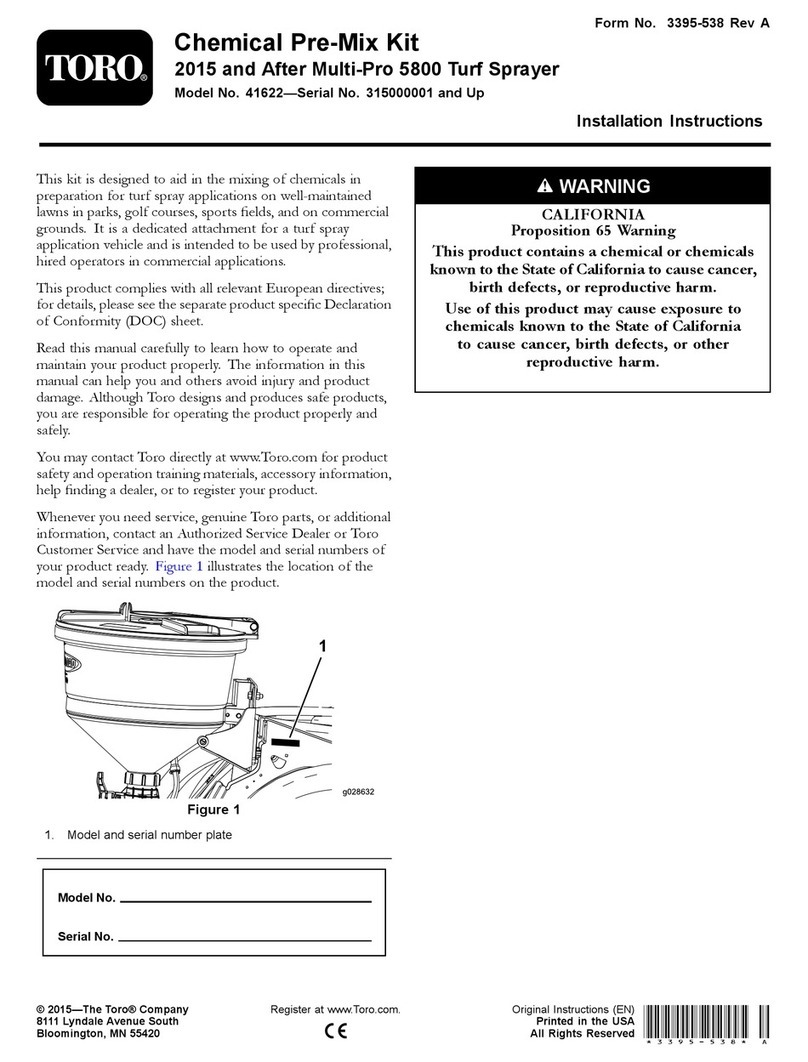
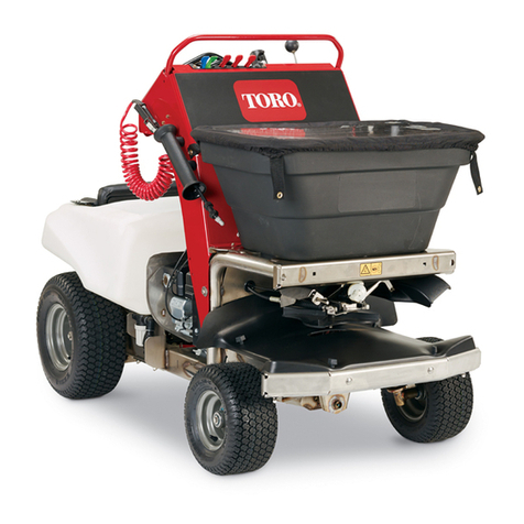
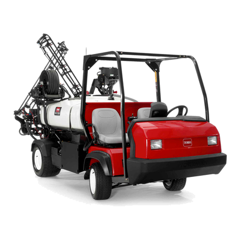
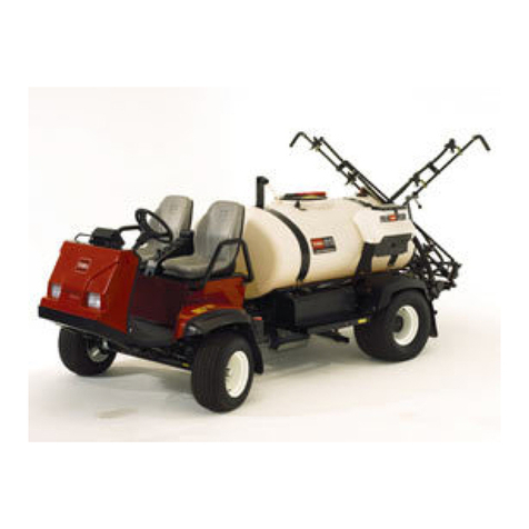
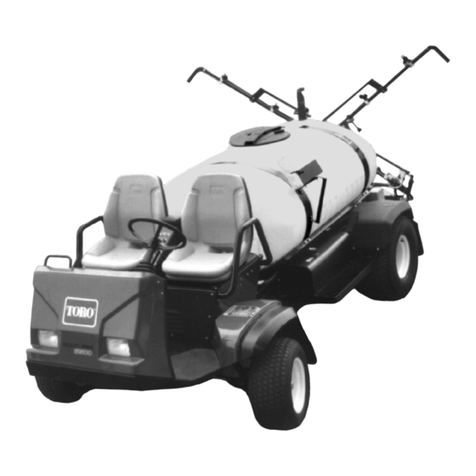
Toro 41249 User manual

FormNo.3414-228RevC
FoamMarkerKit
Serialnumber400000000andAfterMultiPro®1750,5800,and
WMTurfSprayer
ModelNo.41249—SerialNo.317000001andUp
Operator'sManual
Safety
Note:Determinetheleftandrightsidesofthemachinefromthenormaloperatingposition.
SafetyandInstructional
Decals
Safetydecalsandinstructionsareeasilyvisibletotheoperatorandarelocatednearanyarea
ofpotentialdanger.Replaceanydecalthatisdamagedormissing.
decal112-7890
112-7890
1.Foamoutput3.Decrease
2.Increase
Setup
LooseParts
Usethechartbelowtoverifythatallpartshavebeenshipped.
ProcedureDescriptionQty.Use
1Nopartsrequired–Preparethemachine
2Foamtubingassembly(bulk)1Preparethetubing.
©2022—TheToro®Company
8111LyndaleAvenueSouth
Bloomington,MN55420
Registeratwww.T oro.com.OriginalInstructions(EN)
PrintedintheUSA
AllRightsReserved*3414-228*

ProcedureDescriptionQty.Use
Regulatingvalve,capmount1
Regulatingvalve,mount1
3Decal(112-7890)1
Installthefoamcontrolvalve.
4Foammarkernishingkit(sold
separately)1Installthefoammarkernishingkitand
thebracket.
Foamtube1
5Cableties8Routethefoamtubes.
Compressionnut(blue)2
Compressionnut(white)2
Brackets4
Spacers4
Setscrews4
Mountingrod2
6
Foam-nozzleassemblies2
Installthefoamnozzles.
7Nopartsrequired–Connecttheboomsectiontubes.
SeparateinstructionsforinstallingthefoammarkerkitaredenotedineachstepoftheSetup,wherespecic
proceduresaredifferentfrom1machinetoanother.Pleaselookfortheheadingdescribinginstructionsspecic
tothemachinethatyouareworkingwithbeforeproceedingwitheachstepoftheSetup.
Note:Thisfoammarkerkitrequiresamountingbracketspecicallydesignedforyourmachine.Before
installingthiskit,contactanauthorizedT orodistributortoobtaintheFoamMarkerFinishingKitforyourmachine.
1
PreparingtheMachine
NoPartsRequired
Procedure
CAUTION
Chemicalsarehazardousandcancause
personalinjury.
•Readthedirectionsonthechemicallabels
beforehandlingthechemicalsandfollow
allmanufacturerrecommendationsand
precautions.
•Keepchemicalsawayfromyourskin.
Shouldcontactoccur,washtheaffected
areathoroughlywithsoapandcleanwater.
•Weargogglesandanyotherprotective
equipmentrecommendedbythechemical
manufacturer.
1.Parkthemachineonalevelsurface,engagethe
parkingbrake,andshutoffthesprayerpump.
2.Lowertheouterbooms.
3.Shutofftheengineandremovethekey.
4.Cleanthesprayer;refertoCleaningtheSprayer
inthemachineOperator’sManual.
2
PreparingtheTubing
Partsneededforthisprocedure:
1Foamtubingassembly(bulk)
Procedure
1.Measurethelengthoftubingfromthebulkloop
andcutitaccordingtothetablesthatfollow.
Note:Setasidetheremainingtubing.
2.Ateachendofthecuttubinglengths,remove7
to10cm(3to4inches)oftheblacksheathto
exposetheblueandcleartubing.
Note:ForMultiPro5000Seriesmachines,use
onlyasectionofcleartubeforthecompressor
totankloop.
2

MultiPro1750Sprayers
ClearandBlue
Tubes
Quantity
Rightboomfoamtubes5.5m(18ft)1
Leftboomfoamtubes4.9m(16ft)1
Foamdensitycontrol
tubes
N/AN/A
Compressortotank
loop-backtube
92cm(3ft)1
MultiPro5800Sprayers
Clear
andBlue
Tubes
QuantityClear
Tube
Only
Quantity
Rightboom
foamtubes
4.3m(14
ft)
1N/AN/A
Leftboom
foamtubes
4.9m(16
ft)
1N/AN/A
Foamdensity
controltubes
4.9m(16
ft)
1N/AN/A
Compressor
totanktubes
N/AN/A92cm
(3ft)
1
WMMultiProSprayers
ClearandBlue
Tubes
Quantity
Rightboomfoamtubes5.5m(18ft)1
Leftboomfoamtubes4.9m(16ft)1
Foamdensitycontrol
tubes
N/AN/A
Compressortotank
loop-backtube
92cm(3ft)1
3
InstallingtheFoamControl
Valve
Partsneededforthisprocedure:
1Regulatingvalve,capmount
1Regulatingvalve,mount
1Decal(112-7890)
InstallingtheFoamControlValve
1750SeriesandWM(Workman)TurfSprayer
Systems
1.Locatetheblacktankcapontheendofthe
foam-markertankassembly(Figure1).
g206580
Figure1
1.Tankcap4.Blueltertube(insidethe
tank)
2.Fittingonthetankcap
(connectedwiththeblue
ltertube)
5.Gasket
3.Bluecompressionnut6.Cap-mountedregulating
valve
2.Unscrewthetankcapandliftitfromthetank
enoughtoseetheblueltertube(Figure1).
3

3.Removethebluecompressionnutfromthe
ttingonthetankcapconnectedtotheblue
ltertubeinsidethetank(Figure1).
4.Installthecap-mountedregulatingvalveand
gasketontothettingofthetankcapand
positionthevalveasshowninFigure1.
InstallingtheTankLoop-Back
TubingattheTank
MultiPro1750SeriesandWM(Workman)Turf
SprayerSystems
1.Assemblebluecompressionnut(Figure2)that
youremovedinstep3ofInstallingtheFoam
ControlValve(page3)ontothebluetubeofthe
compressortotankloop-backtubingthatyou
cutin2PreparingtheTubing(page2).
g206581
Figure2
1.Fitting(cap-mounted
regulatingvalve)
4.Fittingonthetankcap
2.Bluecompressionnut5.Whitecompressionnut
3.Bluetube(compressorto
tankloop-backtubing)
6.Whitetube(compressorto
tankloop-backtubing)
2.Assemblethebluetubeandbluenutintothe
ttingofthecap-mountedregulatingvalve,and
tightenthecompressionnutbyhand(Figure2).
3.Threadthetankcapontotheneckofthetank.
4.Removethewhitecompressionnutfromthe
ttingonthetankcap(Figure2).
5.Assemblewhitecompressionnutontotheclear
tubeofthecompressortotankloop-backtubing
(Figure2).
6.Assemblethecleartubeandwhitenutintothe
ttingofthecap,andtightenthecompression
nutbyhand.
InstallingtheTankLoop-Back
TubingattheCompressor
MultiPro1750SeriesandWM(Workman)Turf
SprayerSystems
1.Routethecompressortotankloop-backtubes
92cm(3ft)fromthecaptothecompression
nutsatthesideofthecompressor(Figure3).
4

g206595
Figure3
MultiProWMsprayershown;MultiPro1750sprayeris
similar
1.Towardthecompressor5.Cap-mountedregulating
valve
2.Cleartube—compressor
totankloop-backtube92
cm(3ft)
6.Compressionnut
(blue—compressortting)
3.Whitecompression
nut—cap
7.Compressionnut
(white—compressor
tting)
4.Bluetube—compressorto
tankloop-backtube92cm
(3ft)
2.Removethewhitecompressionnutand
assembleitontothecleartube(Figure3).
3.Assemblethecleartubeandwhitecompression
nutontothettingatthesideofthecompressor,
andtightenthewhitecompressionnutbyhand
(Figure3).
4.Removethebluecompressionnutfromthe
ttingatthesideofthecompressor(Figure3).
5.Assemblethebluetubeandbluecompression
nutontothettingatthesideofthecompressor,
andtightenthebluecompressionnutbyhand
(Figure3).
ConnectingtheLoop-BackTube
andFoamDensityTubesatthe
TankandCompressor
MultiPro5800SeriesSprayers
1.Removethewhitecompressionnut(Figure4)
ttingatthecapforthetank,andassembleit
ontothecleartube92cm(3ft).
g411634
Figure4
1.Cleartube—92cm(3ft)4.Compressionnut
(blue—captting)
2.Cleartube—foamdensity
tubes4.9m(16ft)
5.Frontofthemachine
3.Compressionnut
(white—captting)
2.Assemblethecleartubeandwhitecompression
nutontothettingatthecapforthetank,and
tightenthewhitecompressionnutbyhand
(Figure4).
5

3.Routethefreeendofthecleartube92cm(3ft)
fromthettingofthecaptothettingattheside
ofthecompressorwiththewhitecompression
nut(Figure4andFigure5).
g411623
Figure5
1.Compressionnut
(white—compressor
tting)
4.Bluetube—foamdensity
tubes4.9m(16ft)
2.Cleartube—foamdensity
tubes4.9m(16ft)
5.Compressionnut
(blue—compressortting)
3.Cleartube—92cm(3ft)
4.Removethewhitecompressionnut(Figure5)
andassembleitontothecleartube92cm(3ft).
5.Assemblethecleartubeandwhitecompression
nutontothettingatthesideofthecompressor,
andtightenthewhitecompressionnutbyhand
(Figure5).
6.Removethebluecompressionnutfromthe
ttingatthesideofthecompressor(Figure5).
7.Assemblethebluecompressionnutontothe
bluetube(Figure5)ofthefoamdensitytubes
4.9m(16ft).
8.Assemblethebluetubeandbluecompression
nutontothettingatthesideofthecompressor,
andtightenthebluecompressionnutbyhand
(Figure5).
9.Removethebluecompressionnutfromthe
ttingatthecapforthetank(Figure4).
10.Assemblethebluecompressionnutontothe
cleartube(Figure4)ofthefoamdensitytubes
4.9m(16ft).
11.Assemblethecleartubeandbluecompression
nutontothettingatthecapforthetank,
andtightenthebluecompressionnutbyhand
(Figure4).
RoutingtheFoam-Density-Control
Tubes
MultiPro5800SeriesSprayers
1.Routethefoamdensitytubes4.9m(16ft)
forwardfromthetankandcompressorbracket
(locatedbelowthechemicaltankandbehind
thefueltank)alongtheframechannelofthe
machine,andtowardtheareaundertheseat
box(Figure6).
g007700
Figure6
1.Foamtube2.Fueltank
2.Lifttheseat,andcontinuetoroutethetube
forwardalongthewireharnessofthemachine,
throughthesupportclamp,andundertheoor
plate(Figure7).
g195758
Figure7
MultiPro5800sprayershown
1.Frontofthemachine3.Supportclamp
2.Tubepair14.9m(16ft)
3.Routethetubetothevalvemount.
•Formodelyear2015andearliersprayers:
Routethetubealongtheexistingwire
harnessthroughtheconsoleopening(Figure
9).
6

Note:Theconsoleopeningisunderneath
thevalvemount.
g206084
Figure8
1.Tubepair14.9m(16ft)3.Valvemount
2.Consoleopening
•Formodelyear2016andlatersprayers:
Routethetubealongtheexistingwire
harnessthroughtheconsoleopeningandto
thefrontoftheseatbase(Figure8).
g206083
Figure9
1.Consoleopening
(underneaththevalve
mount)
3.Valvemount
2.Tubepair14.9m(16ft)
4.Securethetubestotheexistingwireharness
withcableties(Figure9orFigure8).
InstallingtheFoamDensityTubes
andtheFoamControlValve
MultiPro5000SeriesSprayers
1.Loosenandremovethecompressionnutsfrom
thevalvebody(Figure10).
Note:Retainandsetasidethecompression
nuts.
g206568
Figure10
1.Whitetube4.Valvebody
2.Compressionnut5.Valvemount
3.Jamnut6.Bluetube
2.Loosenandremovethejamnutfromthevalve
(Figure10).
Note:Retainandsetasidethejamnut.
3.Usethepreviouslyremovedjamnuttosecure
thevalvetothevalvemount(Figure10).
4.Insertthebluetubeandthewhitetubeintoa
compressionnut(Figure10).
5.Securetheblueandwhitetubestothevalveby
screwingthecompressionnutontothevalve
(Figure10).
6.InstallthedecalasshowninFigure11orFigure
12.
7

g206499
Figure11
MultiPro5800modelyear2015andearlier
1.Valve3.Decal112-7890
2.Valvemount
g206522
Figure12
MultiPro5800modelyear2016andlater
1.Valve3.Valvemount
2.Decal112-7890
4
InstallingtheFoamMarker
FinishingKitandthe
Bracket
Partsneededforthisprocedure:
1Foammarkernishingkit(soldseparately)
Seetheinstallationinstructionsthatcamewith
thefoammarkernishingkit.
5
RoutingtheFoamTubes
Partsneededforthisprocedure:
1Foamtube
8Cableties
RoutingtheFoamTubestothe
Booms
1.Installthefoamtubestothebooms.
Note:Installtheshorterlengthoftubetothe
boomonthesamesideasthebracket;install
thelongertubetotheboomonthesideopposite
ofthebracket.
A.Ontherightboom,installthefoamtube
alongtherearsideoftheuppersupport
pole(Figure13).
Important:Thefoamtubeswillbe
pinchedwhentheboomsareinthe“X”
transportpositioniftheyareinstalledon
thewrongside.
8

g197029
Figure13
MultiPro5000Seriesshown
1.Foamtubeontheright
boom
2.Cableties
B.Aligntheendofthetubewiththeendofthe
uppersupportpole.
Note:Useacabletietosecurethefoam
tubetothebraceusingtheholesinthe
brace(Figure14).
Note:Leaveasmallexcessoftubeat
theendoftheboomtoallowtheboomto
extend.
g007660
Figure14
1.Cabletie
C.Continuetoroutethetubealongtheexisting
boomsupplytube.
Note:Usetiestosecurethetubetothe
braceatthepositionsshowninFigure15.
g007655
Figure15
1.Cableties
D.Repeattheprocessfortheleftboom,but
routethetubealongthefrontsideofthe
uppersupportpole.
Important:Thefoamtubeswillbe
pinchedwhentheboomsareinthe“X”
transportpositioniftheyareinstalledon
thewrongside.
2.Routethe2foamtubesfromtheboomsforward
tothesideofthemachinewiththemounting
bracket(Figure16).
Important:Donotroutethetubeswhere
theywillbepinchedorpulledoutofplace.
g023900
Figure16
MultiPro1750Sprayer
1.Cableties2.Tube
9

g197028
Figure17
MultiPro5800Sprayer
1.Cableties2.Tube
g196997
Figure18
MultiProWMSprayer
1.Cableties2.Tube
3.Usethewiretiesprovidedtosecurethefoam
tubestotheexistingwiringharnessortheboom
supplytubes.
6
InstallingtheFoamNozzles
Partsneededforthisprocedure:
2Compressionnut(blue)
2Compressionnut(white)
4Brackets
4Spacers
4Setscrews
2Mountingrod
2Foam-nozzleassemblies
AssemblingtheCompression
Nuts
1.Assemblethebluecompressionnutontothe
blue(uid)tube(Figure19).
g196925
Figure19
1.Bluetube3.Cleartube
2.Bluecompressionnut4.Whitecompressionnut
2.Assemblethewhitecompressionnutontothe
clear(air)tube(Figure19).
3.Repeatsteps1and2forfoamtubesofthe
boomattheothersideofthemachine.
InstallingtheBrackets
1.Locatethefoamnozzlemountingbracketsand
thespacers.
2.Installtherstbracket3to4inchesfromtheend
oftheupperboomtube.
3.Assemblethebracketandspacerasshown
(Figure20).
Note:Installbothsetsofbracketclampsatthe
rearwardsideoftheupperboomtube.
10

g007666
Figure20
1.Upperboomtube3.Spacer(noteorientation)5.Clampscrew7.Setscrew
2.Lowerhalfofthebracket
clamp
4.Lowerhalfofthebracket
clamp
6.Spacernut8.Mountingrod
4.Installthesecondbracketassembly7to10cm
(3to4inches)inboardfromtherstbracket.
5.Installasetscrewinthetopholeofeachspacer.
6.Installthemountingrod,withthesplineend
outward,intotheholesinthespacers.
Note:Usethesetscrewstosecuretherodin
thedesiredposition.
7.Repeatsteps2through6fortheboomatthe
othersideofthemachine.
11

InstallingtheFoamNozzles
1.Locatethefoamnozzlesinloosepartsand
installanozzletothemountingrodasshown
(Figure21).
g007667
Figure21
1.Spline-endmandrel3.Bluetubeandblue
compressionnut
2.Foamnozzle4.Cleartubeandwhite
compressionnut
2.Connectthebluetubetotheupperbarbandthe
cleartubetothelowerbarb.
3.Securethetubeswiththecompressionnutsthat
youinstalledinAssemblingtheCompression
Nuts(page10).
4.Repeatsteps1through3fortheboomatthe
othersideofthemachine.
7
ConnectingtheBoom
TubesattheCompressor
NoPartsRequired
Procedure
1.Routethefoamtubesfortherightboomas
showninFigure22.
g411476
Figure22
1.Bluetubes6.Electricalconnector
2.Liquidtting(leftboom)7.Airtting(rightboom)
3.Airtting(leftboom)8.Liquidtting(rightboom)
4.Foamtubes(left
boom)—MultiPro1750
andWMMultiProSeries
4.9m(16ft)orMultiPro
5800Series4.9m(16ft)
9.Cleartubes
5.Foamtubes(right
boom)—MultiPro1750
andWMMultiProSeries
5.5m(18ft)orMultiPro
5800Series4.3m(14ft)
2.Insertthecleartubeintotheairttingattheside
compressorplate(Figure22).
3.Insertthebluetubeintotheliquidttingatthe
sidecompressorplate(Figure22).
4.Routethefoamtubesfortheleftboomasshown
inFigure22.
12

5.Insertthecleartubeintotheairttingattheside
compressorplate(Figure22).
6.Insertthebluetubeintotheliquidttingatthe
sidecompressorplate(Figure22).
Operation
UsingtheControls
Rightboomswitch—Thisswitchactivatesthe
compressor,generatingaowofwaterandairtothe
rightboomsection.
Leftboomswitch—Thisswitchactivatesthe
compressor,generatingaowofwaterandairtothe
leftboomsection.
Note:Youcandropthefoamsimultaneouslyfrom
bothboomsections.
Indicatormarkings—Thesemarkingsarelocatedon
thesideofthetank;theyindicatethesolutionlevel
inthetank.
Foamregulatoradjustmentvalve—Thisvalve
controlstheconsistencyofthefoamsolution.
Adjustingthevalve,openingorclosing,controls
theamountofsoapsolutiondeliveredtothefoam
nozzles.Increasingtheowresultsinlarger,more
frequentfoamdrops;decreasingtheowresultsin
smaller,lessfrequentfoamdrops.
Note:Useafoamwithawaterymarkerconsistency
maybehelpfulonwindydays.
Pressurereliefvalve—Pulltheredtabonthetank
capoutwardtorelievepressureinthetank.
FillingtheTankand
AdjustingtheFoamDensity
Important:Flushthesystemwithcleanwater
aftereachuse,especiallyafterusinghardwater.
Donotapplylubricatingoils,grease,orother
petroleumproductstothecompressormotor
assembly.
1.EnsurethatthefoamcompressorOn/Offswitch
isintheOFFposition.
2.Pulloutontheredpressure-relieftab,and
removetheblackcapfromthetank.
3.Pourtheproperamountofwaterintothetank,
andthenaddfoamconcentratethroughthe
openinginthetopofthetankaccordingtothe
manufacturer’sinstructions.
Important:ExtremepHlevels(hardnessor
softness)ofthewaterwillaffecttheamount
offoamconcentrateneeded.
4.Installthecaponthetankandtightenitbyhand.
5.Fortheinitialoperation,openthefoam
densityadjustmentvalve1/8to1/4turn
counterclockwise(Figure23).
13

g207605
Figure23
1.1/4turnopen
6.Startoperatingthemarkingsystemandmakea
testpatternontheground.
Note:Whenyourststartthemarkingsystem,
allow1to2minutesforthefoamtoowthrough
theline.
7.Adjustthefoamdensityadjustmentvalveto
obtainthedesiredconsistencyandsprayas
normal.
Note:Ifyouleavethefoaminthelineformore
than2hours,itmaybecomewatery.Before
operatingafterabreakof2ormorehours,run
themachinefor1to2minutestoremovethe
excesswater.
Ifthefoaminthemachineisverywatery,do
thefollowing:
A.Closethefoamdensityadjustmentvalve
completely.
B.Operatefor2minutes.
C.Wait1minuteandthencheckthe
consistencyofthefoam.
D.Adjustthefoamtoachievethedesired
consistency.
Maintenance
Winterizing
1.Movethevehicleontoalevelsurface,engage
theparkingbrake,stopthepump,andshutoff
theengine.
2.Atthetankcap,pulloutontheredpressure-relief
tab.
3.Removethetankcapfromthetank.
4.Removethehairpinthatsecuresthestrapand
tanktothecompressor.
5.Emptythetankofallsoapandliquids.
6.Assemblethetanktothecompressorwiththe
strapandhairpin.
7.Assemblethecapontothetankandtightenthe
cap.
8.Startthefoam-markercompressorandruneach
foam-markernozzlefor5minutes.
Note:Thisremovesthesolutionfromthe
solenoidsandpreventsdamagefromfreezing.
9.Shutoffthefoam-markercompressor,and
removethekeyfromthekeyswitch.
10.Disassemblethefoamnozzlesandreplacethe
foamsponges.
14

Storage
1.Movethevehicleontoalevelsurface,setthe
parkingbrake,stopthepump,shutoffthe
engine,andremovethekey.
2.Relievepressurewithintankbyopeningthe
tankllcap,installthetankllcap,andhand
tightenit.
3.Disconnecttheairandliquidtubingfromthe
tank.
Note:Replaceairandliquidtubingtogether
withthesuppliedtubingcoupler.
4.Disassemblethefoamnozzlesandreplacethe
foamsponges.
5.Emptythetankofallsoapandliquidstoavoid
damagingthetankfromfreezing.
15

EEA/UKPrivacyNotice
Toro’sUseofYourPersonalInformation
TheT oroCompany(“T oro”)respectsyourprivacy.Whenyoupurchaseourproducts,wemaycollectcertainpersonalinformationaboutyou,eitherdirectly
fromyouorthroughyourlocalTorocompanyordealer.T orousesthisinformationtofullcontractualobligations-suchastoregisteryourwarranty,
processyourwarrantyclaimortocontactyouintheeventofaproductrecall-andforlegitimatebusinesspurposes-suchastogaugecustomer
satisfaction,improveourproductsorprovideyouwithproductinformationwhichmaybeofinterest.Toromayshareyourinformationwithoursubsidiaries,
afliates,dealersorotherbusinesspartnersinconnectiontheseactivities.Wemayalsodisclosepersonalinformationwhenrequiredbylaworin
connectionwiththesale,purchaseormergerofabusiness.Wewillneversellyourpersonalinformationtoanyothercompanyformarketingpurposes.
RetentionofyourPersonalInformation
Torowillkeepyourpersonalinformationaslongasitisrelevantfortheabovepurposesandinaccordancewithlegalrequirements.Formoreinformation
aboutapplicableretentionperiodspleasecontact[email protected].
Toro’sCommitmenttoSecurity
YourpersonalinformationmaybeprocessedintheUSoranothercountrywhichmayhavelessstrictdataprotectionlawsthanyourcountryofresidence.
Wheneverwetransferyourinformationoutsideofyourcountryofresidence,wewilltakelegallyrequiredstepstoensurethatappropriatesafeguardsare
inplacetoprotectyourinformationandtomakesureitistreatedsecurely.
AccessandCorrection
Youmayhavetherighttocorrectorreviewyourpersonaldata,orobjecttoorrestricttheprocessingofyourdata.T odoso,pleasecontactusbyemail
at[email protected].IfyouhaveconcernsaboutthewayinwhichTorohashandledyourinformation,weencourageyoutoraisethisdirectlywithus.
PleasenotethatEuropeanresidentshavetherighttocomplaintoyourDataProtectionAuthority.
374-0282RevC
Table of contents
Other Toro Paint Sprayer manuals

Toro
Toro GeoLink 41624 User manual

Toro
Toro 41188 User manual

Toro
Toro Multi-Pro 5800 User manual

Toro
Toro Multi Pro 41118 User manual

Toro
Toro 41605 User manual

Toro
Toro Multi Pro 1250 User manual

Toro
Toro Ultra Sonic Boom 130-8227 User manual

Toro
Toro Multi Pro 5800 User manual
Toro
Toro Spray Master Series User manual

Toro
Toro MultiPro 1200 User manual

Toro
Toro 41164 User manual

Toro
Toro Pro Control XP User manual

Toro
Toro 41199 User manual

Toro
Toro Multi-Pro 1250 User manual

Toro
Toro 41621 User manual

Toro
Toro 136-0457 User manual

Toro
Toro 41177 Multi-Pro 1250 User manual

Toro
Toro Multi-Pro 5800 User manual

Toro
Toro 41593 User manual

Toro
Toro 41594 User manual