manuals.online logo
Brands
  1. Home
  2. •
  3. Brands
  4. •
  5. Toro
  6. •
  7. Paint Sprayer
  8. •
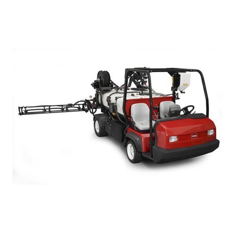
  9. Toro Ultra Sonic Boom 130-8229 User manual

Toro Ultra Sonic Boom 130-8229 User manual

FormNo.3396-881RevA
UltraSonicBoom™FinishingKit
2013andAfterMultiPro®5800TurfSprayer
ModelNo.130-8229
InstallationInstructions
Note:TheUltraSonicBoomLevelingKit(Toropartnumber41219)isrequiredtoinstallthiskit.
Note:Determinetheleftandrightsidesofthemachinefromthenormaloperatingposition.
WARNING
CALIFORNIA
Proposition65Warning
ThisproductcontainsachemicalorchemicalsknowntotheStateofCaliforniato
causecancer,birthdefects,orreproductiveharm.
LooseParts
Usethechartbelowtoverifythatallpartshavebeenshipped.
ProcedureDescriptionQty.Use
Valve-mountbracket1
Hydraulicmanifoldblock(ordered
separately)1
1Hydraulictting(orderedseparately)4
Installthevalve-mountbracket.
Mountingbracket1
Wiringharness1
Electroniccontroller(ordered
separately)1
Bolt(1/4x1-1/8inch)(ordered
separately)4
2
Locknut(1/4inch)(orderedseparately)4
Mounttheelectroniccontroller.
©2015—TheToro®Company
8111LyndaleAvenueSouth
Bloomington,MN55420
Registeratwww.T oro.com.OriginalInstructions(EN)
PrintedintheUSA
AllRightsReserved*3396-881*A
1
InstallingtheValve-Mount
Bracket
Partsneededforthisprocedure:
1Valve-mountbracket
1Hydraulicmanifoldblock(orderedseparately)
4Hydraulictting(orderedseparately)
Procedure
Note:Youcanndthehydraulicmanifoldblockand
hydraulicttingsintheUltrasonicBoomLevelingKit.
1.Disconnectthewiringharnessfromthehydraulic
manifoldblock(Figure1).
Figure1
1.Hose3.Wiringharness
2.Hydraulicmanifoldblock
2.Labelallthehosesconnectedtothehydraulicmanifold
blockanddisconnectthemfromtheblock(Figure1).
3.Loosenthe2hydraulicconnectorsontherightside
andthegaugeportontheleftsideofthehydraulic
manifoldblock(Figure2).
Figure2
Frontsideofthehydraulicmanifoldblock
1.Mountingbracket4.Gaugeport
2.Hydraulicconnector5.Nut(5/16inch)
3.Bolt(5/16x3inch)
4.Removethehydraulicmanifoldblockfromthe
mountingbracket(Figure2).
Note:Retainthefasteners.
5.Removeandretainthe2hydraulicconnectorsand
gaugeportfromthehydraulicmanifold(Figure2).
6.Removethemountingbracketfromthemachine
(Figure3).
Note:Retainthefasteners.
Figure3
1.Bolt(5/16x1inch)2.Nut(5/16inch)
2
7.Installthevalve-mountbracketusingthe2bolts(5/16
x1inch)and2locknuts(5/16inch)thatyoupreviously
removed(Figure4).
Figure4
1.Bolt(5/16x1inch)3.Valve-mountbracket.
2.Nut(5/16inch)
8.InstallthehydraulicttingsintoportsC1throughC4
inthenewhydraulicmanifoldblock(Figure5).
Figure5
Frontsideofthehydraulicmanifoldblock
1.Nut(5/16inch)4.Bolt(5/16x3inch)
2.Hydraulicconnector5.Gaugeport
3.Hydraulictting
9.Installthe2hydraulicconnectorsandgaugeporttothe
newhydraulicmanifoldblock(Figure5).
10.Installthenewhydraulicmanifoldblockontothe
valve-mountbracketwiththe2bolts(5/16x3inch)
and2locknuts(5/16inch)thatyoupreviouslyremoved
(Figure5).
11.Tightenthe2hydraulicconnectorsandgaugeport.
12.Tightenallttingsonthehydraulicmanifoldblockand
valve-mountbracket.
13.Installthehydraulichosesintothettingsinthe
correspondingportsonthehydraulicmanifoldblock.
Important:Ensurethatyouinstallthehoses
correctly.Thehose(3/8inch)fromthereturn
lterconnectstothe“T”portandtheotherhose
(3/8inch)connectstothe“P”port.Thehoses
fromthebaseendofthecylindersconnectports
C1andC3,andthehosesfromtherodendofthe
cylindersconnecttoportsC2andC4.
14.Purgethehydraulicsystem.RefertotheOperator’s
Manualforthemachine.
3
2
MountingtheElectronic
Controller
Partsneededforthisprocedure:
1Mountingbracket
1Wiringharness
1Electroniccontroller(orderedseparately)
4Bolt(1/4x1-1/8inch)(orderedseparately)
4Locknut(1/4inch)(orderedseparately)
Procedure
Note:Youcanndtheelectroniccontroller,bolts,and
locknutsintheUltrasonicBoomLevelingKit.
1.Behindthecontrolconsole,removetheknockoutplug
(Figure6).
Figure6
1.Knockoutplug2.Controlconsole
2.Removethe2boltsandinstallthemountingbracketto
themachineseatframe(Figure7).
Figure7
1.Mountingbracket2.Bolt
3.Securetheelectroniccontrollertothemounting
bracketwith4bolts(1/4x1-1/8inch)and4locknuts
(1/4inch)asshowninFigure8.
Figure8
1.Mountingbracket3.Bolt(1/4x1-1/8inch)
2.Locknut(1/4inch)4.Electroniccontroller
4.Routetheelectroniccontrollerterminalofthewiring
harnessthroughtheknockouthole.
4
5.Connecttheterminalofthewiringharnessintothe
electroniccontroller(Figure9).
Note:Thecontrollerconnectioniskeyedandcanbe
connectedinonly1way.
Figure9
1.Electroniccontroller2.Wiringharnessterminal
6.Routethewiringharnesstothehydraulicmanifold.
Figure10
7.ContinueinstallingtheUltraSonicBoomLevelingKit;
refertotheInstallationInstructionsforthekit.
5
Notes:
6
Notes:
7

Other Toro Paint Sprayer manuals

Toro Multi Pro 1750 User manual

Toro

Toro Multi Pro 1750 User manual

Toro Multi Pro 5800 41623 User manual

Toro

Toro Multi Pro 5800 41623 User manual

Toro 41177 Multi-Pro 1250 User manual

Toro

Toro 41177 Multi-Pro 1250 User manual

Toro Multi Pro 5800 User manual

Toro

Toro Multi Pro 5800 User manual

Toro 41440 Specifications

Toro

Toro 41440 Specifications

Toro Multi Pro 41240 User manual

Toro

Toro Multi Pro 41240 User manual

Toro 41581 User manual

Toro

Toro 41581 User manual

Toro Multi Pro 5800-D User manual

Toro

Toro Multi Pro 5800-D User manual

Toro 34230 User manual

Toro

Toro 34230 User manual

Toro Multi-Pro 5800 User manual

Toro

Toro Multi-Pro 5800 User manual

Toro 41593 User manual

Toro

Toro 41593 User manual

Toro Multi-Pro 5800 User manual

Toro

Toro Multi-Pro 5800 User manual

Toro 41228 User manual

Toro

Toro 41228 User manual

Toro Multi Pro 5800 User manual

Toro

Toro Multi Pro 5800 User manual

Toro 41198 Multi-Pro 1250 User manual

Toro

Toro 41198 Multi-Pro 1250 User manual

Toro 136-0457 User manual

Toro

Toro 136-0457 User manual

Toro Multi Pro 1200 User manual

Toro

Toro Multi Pro 1200 User manual

Toro 41249 User manual

Toro

Toro 41249 User manual

Toro Multi Pro 1200 User manual

Toro

Toro Multi Pro 1200 User manual

Toro Multi Pro 41118 User manual

Toro

Toro Multi Pro 41118 User manual

Toro Multi Pro 5800-D User manual

Toro

Toro Multi Pro 5800-D User manual

Toro MultiPro 1200 User manual

Toro

Toro MultiPro 1200 User manual

Toro 41188 User manual

Toro

Toro 41188 User manual

Toro Multi Pro WM 41240 User manual

Toro

Toro Multi Pro WM 41240 User manual

Popular Paint Sprayer manuals by other brands

Graco 248650 Repair and parts

Graco

Graco 248650 Repair and parts

HDX 1501HDXA user manual

HDX

HDX 1501HDXA user manual

Agrimate AM-708 user manual

Agrimate

Agrimate AM-708 user manual

AIRLESSCO SL810 Service & operation manual

AIRLESSCO

AIRLESSCO SL810 Service & operation manual

Fervi 0024 Operation and maintenance manual

Fervi

Fervi 0024 Operation and maintenance manual

KISANKRAFT KK-PSK-18 Operation manual

KISANKRAFT

KISANKRAFT KK-PSK-18 Operation manual

BODYSHOP Paintlight Use and maintenance manual

BODYSHOP

BODYSHOP Paintlight Use and maintenance manual

Milwaukee M4910-20 Operator's manual

Milwaukee

Milwaukee M4910-20 Operator's manual

POLINS GARDEN HOBBY 5 Original instructions

POLINS

POLINS GARDEN HOBBY 5 Original instructions

DeVilbiss FUNCY JGX-3C-343 Operation manual

DeVilbiss

DeVilbiss FUNCY JGX-3C-343 Operation manual

EINHELL 41.334.20 Original operating instructions

EINHELL

EINHELL 41.334.20 Original operating instructions

Graco 695 HI Operation

Graco

Graco 695 HI Operation

C.A. Technologies CPR quick guide

C.A. Technologies

C.A. Technologies CPR quick guide

Spraying Systems GunJet PW4000A user guide

Spraying Systems

Spraying Systems GunJet PW4000A user guide

Enduraplas IceMaster Systems Liquid Master W Series owner's manual

Enduraplas

Enduraplas IceMaster Systems Liquid Master W Series owner's manual

Graco 24H685 operation & maintenance

Graco

Graco 24H685 operation & maintenance

Toolland DTB10001 user manual

Toolland

Toolland DTB10001 user manual

IMC IMCNL-HD-PY02 Series Operation manual

IMC

IMC IMCNL-HD-PY02 Series Operation manual

manuals.online logo
manuals.online logoBrands
  • About & Mission
  • Contact us
  • Privacy Policy
  • Terms and Conditions

Copyright 2025 Manuals.Online. All Rights Reserved.