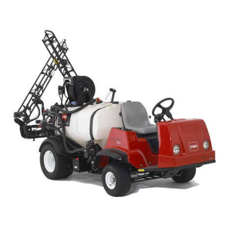
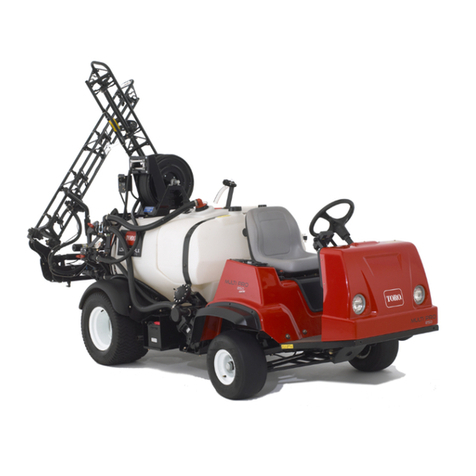
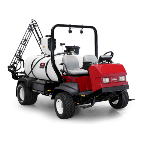
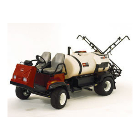
Toro Multi Pro 5800-D User manual

FormNo.3406-992RevA
ValveConversionKit
MultiPro®5800-DTurfSprayer
ModelNo.132-4276
InstallationInstructions
Thevalveconversionkitisakitthatreplacesthesprayercontrolvalvesandrelatedcomponentsforaturfsprayapplication
vehicle.
YoumaycontactTorodirectlyatwww .Toro.comforproductsafetyandoperationtrainingmaterials,accessoryinformation,
helpndingadealer,ortoregisteryourproduct.
WARNING
CALIFORNIA
Proposition65Warning
ThisproductcontainsachemicalorchemicalsknowntotheStateofCaliforniato
causecancer,birthdefects,orreproductiveharm.
UseofthisproductmaycauseexposuretochemicalsknowntotheStateofCalifornia
tocausecancer,birthdefects,orotherreproductiveharm.
Safety
WARNING
Chemicalsubstancesusedinthespraysystemmaybehazardousandtoxictoyou,bystanders,animals,
plants,soils,orotherproperty.
•Carefullyreadandfollowthechemicalwarninglabelsandmaterialsafetydatasheets(MSDS)forall
chemicalsusedandprotectyourselfaccordingtothechemicalmanufacturer'srecommendations.For
example,useappropriatepersonalprotectiveequipment(PPE),includingfaceandeyeprotection,
gloves,orotherequipmenttoguardagainstpersonalcontactwithachemical.
•Theremaybemorethan1chemicalusedandinformationoneachchemicalshouldbeassessed.
•Refusetooperateorworkonthesprayerifthisinformationisnotavailable.
•Beforeworkingonaspraysystem,ensurethatthesystemhasbeentriplerinsedandneutralized
accordingtotherecommendationsofthechemicalmanufacturer(s)andthatallthevalveshavebeen
cycled3times.
•Verifythatthereisanadequatesupplyofcleanwaterandsoapnearby,andimmediatelywashoffany
chemicalsthatcontactyou.
©2016—TheToro®Company
8111LyndaleAvenueSouth
Bloomington,MN55420
Registeratwww.Toro.com.OriginalInstructions(EN)
PrintedintheUSA
AllRightsReserved*3406-992*A

SafetyandInstructionalDecals
Safetydecalsandinstructionsareeasilyvisibletotheoperatorandarelocatednearanyareaofpotential
danger.Replaceanydecalthatisdamagedormissing.
127-6976
1.Decrease2.Increase
127-6979
1.Pump-returnow3.Agitationow
2.Flow
127-6981
1.Bypass-returnow3.Boomspray
2.Flow
127-6982
1.Pumpreturnow2.Boomspray
2

Installation
LooseParts
Usethechartbelowtoverifythatallpartshavebeenshipped.
ProcedureDescriptionQty.Use
1Nopartsrequired–Preparetoinstallthekit.
2Nopartsrequired–Disconnecttherearwireharnessfrom
theoptionalattachment.
3Nopartsrequired–Disconnectingthepressure-sensetube
forthedashgauge.
4Rearwireharness1Removetherearwireharnessforthe
machine.
5Nopartsrequired–Removethebypass,drain,andagitation
components.
6Nopartsrequired–Disassemblingthesupplyhose.
7Nopartsrequired–Removethevalvesupportand
boom-sectionvalves.
Sprayer-valveassembly1
Cover—52mm(2-1/16inches)1
Gasket—25x35mm(1x1-3/8inches)1
Flangeclamp—40to64mm(1-9/16to
2-1/2inches)1
Valvemount1
Flange-headbolts(5/16x1inch)5
8
Flangelocknuts(5/16inch)5
Assemblethevalvestothevalvemount.
9Nopartsrequired–Installthevalvemounttothemachine.
Screw(6-32x5/8inch)1
Handle1
Agitationthrottlevalve1
Bracket(nylon)1
Agitation-valvebracket1
Bolt(6x12mm)1
Agitationsupplyhose1
Agitation-nozzleassembly1
Agitationbypasshose—25x254mm
(1x10inches)1
Gasket—25x35mm(1x1-3/8inches)1
10
Flangeclamp—40to64mm(1-9/16to
2-1/2inches)1
Installtheagitationshutoffvalve,
nozzles,andhoses.
Manifoldsupplyhose(1x25inches)1
Gasket—25x35mm(1x1-3/8inches)1
11Flangeclamp—40to64mm(1-9/16to
2-1/2inches)1
Installthemanifoldsupplyhose.
3

ProcedureDescriptionQty.Use
Eductorshutoffvalve1
Shutoff-valvebracket1
Flangelocknuts(1/4inch)1
Gasket—25x35mm(1x1-3/8inches)1
Flangeclamp—40to64mm(1-9/16to
2-1/2inches)1
Agitationbypasshose—25x337mm
(1x13-1/4inches)1
Gasket—25x35mm(1x1-3/8inches)1
Flangeclamp—40to64mm(1-9/16to
2-1/2inches)1
Pressure-reliefhose—2.5x29.8cm(1
x11-3/4inches)1
Sprayersupplyhose—2.5x48.6cm(1
x19-1/8inches)1
12
Eductorsupplyhose—2.5x156.5cm
(1x61-5/8inches)1
Installtheshutoffvalveandhosesfor
thechemicalpremixkit.
Bypassanddrain-hoseassembly1
Supportclamp1
Flange-headbolt(5/16x3/4inch)1
13Washer(5/16inch)1
Installthesectionbypasshoseand
drain-hoseassembly.
Supplyhose—leftboomsection—2x
205cm(3/4x80-13/16inches)1
Supplyhose—centerboomsection—2
x58cm(3/4x22-13/16inches)1
14Supplyhose—rightboomsection—2x
170cm(3/4x66-13/16inches)1
Installthesprayernozzlehoses.
Flangeshutoffvalve1
Bracket(nylon)1
90°elbow(withpressureport)1
Gasket—25x35mm(1x1-3/8inches)1
Flangeclamp—40to64mm(1-9/16to
2-1/2inches)1
Washer(5/16x13/16inch)4
Bolt(6x16mm)4
Hoseclamp2
Quick-connecttting(socket)1
Straightbarbedtting(1/2inch)1
Hose—1.3x762cm(1/2x300inches)1
Hose—1.3x180cm(1/2x71inches)1
15
Cableties3
Installtheshutoffvalveandhosefor
theoptionalspraygunkitorelectric
hose-reelkit.
Rearwireharness1
16Cabletie3
Assembletherearwiringharnesstothe
machine.
17Nopartsrequired–Connecttherearwireharness.
18Jumperharness(optionalspraygunkit
orelectrichose-reelkit)1Connecttherearwireharnesstothe
OptionalAttachments
19Nopartsrequired–Connectthepressure-sensetubefor
thedashgauge.
20Nopartsrequired–Completetheinstallationofthevalve
conversionkit.
4

1
PreparingtoInstalltheKit
NoPartsRequired
PreparingtheMachine
1.Movethemachinetoalevelsurface(Figure1).
Figure1
2.Settheparkingbrake(Figure1).
3.Shutofftheengineandremovethekey(Figure1).
PreparingtheSprayerandOptional
RinseTank
1.Cleanthesprayer;refertoCleaningtheSprayerinthe
Operator’sManualforthemachine.
Important:Youmustcompletelyemptythe
sprayertankbeforeinstallingthevalveconversion
kit.
2.Formachineswiththeoptionaltank-rinsekit,
performthefollowing:Pumpthewaterfromthe
rinsetankintothesprayertank;refertoOperating
theRinseKitintheInstallationInstructionsforthe
Tank-RinseKit.
3.Drainthewaterfromthesprayertank(Figure2);refer
toCleaningtheSprayerintheOperator’sManualforthe
machine.
Figure2
1.Lynchpin5.Cable(lynchpin)
2.Mountpeg6.Flange-headbolt(5/16x
1inch)
3.Drainvalve7.Support(hydraulictank)
4.Flangelocknut(5/16inch)8.Rubberwasher
4.Removetheange-headbolt(5/16x1inch)andange
locknut(5/16inch)thatsecurethecableofthelynch
pintothehydraulic-tanksupport(Figure2).
Note:Retainthelynchpin,angelocknut,ange-head
bolt,and2rubberwashersforinstallationInstalling
theDrainValve(page36).
5

DisconnectingtheBattery
1.Extendtheleftandrightboomsectionstothe
horizontalposition.
2.RotatetheKEYSWITCHtotheOFFposition,and
removethekey;refertotheOperator’sManual.
3.Removethebatterycoveranddisconnectthenegative
(black—ground)cablefromthebatterypost(Figure
3andFigure4).
WARNING
Electricalsparkscancausethebatterygasses
toexplode,resultinginpersonalinjury.
Incorrectbatterycableroutingcoulddamage
thesprayerandcables,causingsparks.
•Alwaysdisconnectthenegative(black)
batterycablebeforedisconnectingthe
positive(red)cable.
•Alwaysconnectthepositive(red)battery
cablebeforeconnectingthenegative
(black)cable.
Batteryterminalsormetaltoolscouldshort
againstmetalsprayercomponents,causing
sparks.
•Whenremovingorinstallingthebattery,
donotallowthebatteryterminalstotouch
anymetalpartsofthesprayer.
•Donotallowmetaltoolstoshortbetween
thebatteryterminalsandmetalpartsof
thesprayer.
•Alwayskeepthebatterystrapinplaceto
protectandsecurethebattery.
G014029
1
2
3
Figure3
1.Batterycover3.Buckle
2.Strap
Figure4
1.Positivebatterycable3.Negativebatterypost
2.Positivebatterypost4.Negativebatterycable
4.Disconnectthepositive(red)cablefromthebattery
post(Figure4).
5.Tiltbothseatsforwardandsecurethembymoving
theproprodsintothedetentsattheendoftheslots
atthecenter-consolebase.
6.Allowtheenginetocoolcompletely.
6

2
DisconnectingtheRearWire
HarnessfromtheOptional
Attachments
NoPartsRequired
DisconnectingtheWireHarnessfrom
theOptionalSprayGunKitorElectric
Hose-ReelKit
1.Atthebackofthesprayertank,locatethewireharness
forthespraygunkitorelectrichose-reelkit(Figure5).
Figure5
1.Controlbox(spraygunkit
orelectrichose-reelkit)
3.6-socket(rearwire
harness)
2.6-pinconnector
(harness—spraygun
kitorelectrichose-reelkit)
2.Disconnectthe6-pinconnectoroftheharnessforthe
spraygunkitorelectrichosereel-kitfromthe6-socket
oftherearwireharness(Figure5).
DisconnectingtheCompressorforthe
Foam-MarkerKit
1.Atthebackofthefoam-markertank,locatethewire
harnessatthecompressor(Figure6).
Figure6
1.Compressor3.4-socketconnector(wire
harnessforthenishing
kit)
2.4-pinconnector(wire
harnessforthe
compressor)
2.Disconnectthe4-pinconnectorofthecompressor
harnessfromthefromthe4-socketconnectorofthe
rearwireharnessofthemachine(Figure6).
DisconnectingthePumpforthe
Tank-RinseKit
1.Atthebackofthemachine,presstogetherthesidesof
therinse-pumpcoverandliftthecoverupuntilthe
tabsofthecovercleartheslotsinthesaddleplate,and
removethecoverfromthemachine(Figure7).
Figure7
7

2.Disconnectthe6-pinconnectoroftherinse-pump
harnessfromthe6-socketconnectoroftherearwire
harness(Figure8).
Figure8
1.Rinsepump3.6-pinconnector
(rinse-pumpharness)
2.6-socketconnector(rear
wireharness)
DisconnectingtheWireHarnessfrom
theOptionalPro-ControlKit
Disconnectthe3-pinconnectoroftheow-meterharness
fromthe3socketconnectoroftherearwireharnessofthe
machine(Figure9).
Figure9
1.3-pinconnector
(ow-meterharness)
3.Flowmeter
2.3socketconnector(rear
wireharness—machine)
3
Disconnectingthe
Pressure-SenseTubefor
theDashGauge
NoPartsRequired
DisconnectingthePressure-Sense
TubefortheDashGauge—Machines
WithoutanOptionalHose-ReelKit
Note:Ifyourmachineisequippedwithanoptionalspray
gunkit,refertoDisconnectingPressure-SenseTubeand
SupplyHose—OptionalSpray-GunKitorElectricHose-Reel
Kit(page9).
1.Pressinthecollarforthetubecouplerintheported-cap
ttingoftheright-boom-sectionvalve(Figure10).
Figure10
1.Tubecoupler(endcap
oftheright-boom-section
valve)
3.Pressure-sensetube
2.Ported-captting
2.Pullthepressure-sensetubeforthedashgaugeoutof
thetubecoupler(Figure10).
8

DisconnectingPressure-SenseTube
andSupplyHose—OptionalSpray-Gun
KitorElectricHose-ReelKit
1.PressinthecollarsforthetubecouplersintheT-tting
inthepressureporttting(Figure11orFigure12).
Figure11
OptionalSprayGunKit
1.Tubecoupler(pressure
tting—bypassvalve)
3.Pressure-sensetube
(dash-pressuregauge)
2.Pressure-sensetube
(spraygunpressure
gauge)
Figure12
ElectricHose-ReelKit
1.Tubecoupler(pressure
tting—bypassvalve)
3.T-tting
2.Pressure-sensetube
(spraygunpressure
gauge)
4.Pressure-sensetube
(dash-pressuregauge)
2.Removethepressure-sensetubeforthedashgauge
fromthetubecoupler(Figure11orFigure12).
3.Removethepressure-sensetubeforthespraygun
pressuregaugeorfromthetubecoupler(Figure11or
Figure12).
4.RemovetheT-ttingfromthepressure-porttting
(Figure13).
Note:RetaintheT-ttingforinstallationin
ConnectingthePressureSense-Tube—OptionalSpray
GunKitorOptionalElectricHose-ReelKit(page52).
Figure13
1.Pressure-portttingtube2.T-tting
9

4
RemovingtheRearWire
HarnessfortheMachine
Partsneededforthisprocedure:
1Rearwireharness
DisconnectingtheFrontandRearWire
Harnesses
Note:Useamachinehoistwhendisconnectingthefront
andrearwireharnesses.
Figure14
1.Frontofthemachine2.Connectorinterfaces(frontandrearwireharnesses)
1.Fromunderthemachinealongtherightframetube,
locatetheelectricalconnectorsforthefrontandrear
wireharnessesofthemachine(Figure14).
2.Disconnectthe6pairsofconnectorsbetweenthefront
andrearwireharnessesasshowninFigure15through
Figure19.
10

Figure15
1.10-socket
connector—sprayer-harness
interconnect(frontwire
harness)
3.Frontofthemachine
2.10-pin
connector—sprayer-harness
interconnect(rearwire
harness)
Figure16
1.3-socketconnector—ow
meter(frontwireharness)
3.Frontofthemachine
2.3-pinconnector—ow
meter(rearwireharness)
Figure17
1.8-socket
connector—sprayer-harness
interconnect(frontwire
harness)
3.Frontofthemachine
2.8-pin
connector—sprayer-harness
interconnect(rearwire
harness)
Figure18
1.2-socketconnector—rinse
pump(frontwireharness)
3.Frontofthemachine
2.2-pinconnector—rinse
pump(rearwireharness)
Figure19
1.10-pin
connector—sprayer-harness
interconnect(frontwire
harness)
3.Frontofthemachine
2.10-socket
connector—sprayer-harness
interconnect(rearwire
harness)
3.Removethe3push-infastenersoftherearwireharness
thatsecuretheharnessattheholesintherightframe
tubeofthemachine(Figure20).
Figure20
1.Rearwireharness3.Frontofthemachine
2.Rightframetube4.Push-infastener
11

DisconnectingtheWireHarnessfrom
theSprayerComponents
1.Atthebackofthemachine(betweentherightframe
tubeandtherightfender),disconnectthe3-pin
connectorofthespeed-sensorharnessattheright
hydraulic-tractionmotorfromthe3-socketconnector
oftherearwireharness(Figure21).
Figure21
1.3-socketconnector(rear
wireharness)
3.Frontofthemachine
2.3-pinconnector
(hydraulic-motorharness
2.Atthebackofthemanifoldmount,disconnectthe
3-socketconnectorfromtheagitationvalveandthe
3-socketconnectorsfromthe3boom-sectionvalves
(Figure22).
Figure22
1.3-socketconnectors
(SPRAYGUNVALVE)
3.3-socketconnector
(AGITATIONVALVE)
2.3-socketconnectors
(RIGHTSPRAYVALVE/
CENTERSPRAYVALVE/
RIGHTSPRAYVALVE)
4.3-socketconnector
(EDUCTORVALVE)
3.Removethepush-infastenersthatsecuretherearwire
harnesstotheholesattheforwardsideandlowerplate
ofthemanifoldmount(Figure23).
Figure23
1.Manifoldmount(lower
plate)
3.Push-infasteners
2.Manifoldmount(forward
side)
4.Rearwireharness
4.Formachineswithouttheultra-sonicboomkit—atthe
backofthemachine,disconnectthefollowing2-socket
connectors(Figure24)forthelift-cylindermanifold
asfollows:
•Right—upsolenoid
•Left—upsolenoid
•Enablesolenoid
•Right—downsolenoid
•Left—downsolenoid
12

Figure24
1.Right—up(solenoidand
main-harnessconnector)
4.Enable(solenoidand
main-harnessconnector)
2.Left—up(solenoidand
main-harnessconnector)
5.Right—down(solenoid
andmain-harness
connector)
3.Frontofthemachine6.Left—down(solenoidand
main-harnessconnector)
5.Atthebackofthemachine—inboardofthesprayer
pump,disconnectthe2-socketconnectoroftherear
wireharnessfromthe2-pinconnectoroftherelayfor
thepump(Figure25).
Figure25
1.2-pinconnector(pump
relay)
3.Frontofthemachine
2.2-socketconnector(rear
wireharness)
6.Removethepush-infastenerthatsecurestherearwire
harness(Figure26)totheholesintherearcrosstube
(rearwardofthehydraulic-tractionmotors).
Figure26
1.Sprayerpump3.Rearwireharness
2.Rearcrosstube4.Push-infastener
7.Removethepressure-sensetubeforthedashgauge
fromtherearwireharnessfromthemachine(Figure
27).
Figure27
1.Pressure-sensetube
(dashgauge)
2.Rearwireharness
8.Removetherearwireharnessfromthemachine.
Note:Younolongerneedtherearwireharnessthat
youremovedfromthemachine.
13

5
RemovingtheBypass,Drain,
andAgitationComponents
NoPartsRequired
RemovingtheBypassandDrainHoses
1.Removetheretainerthatsecuresthe90°hosetting
totheadapterttingatthebottomofthesprayertank
(Figure28).
Note:RetaintheretainerforinstallationinInstalling
theTankDrainHose(page35).
Figure28
1.Adaptertting(bottomof
thesprayertank)
4.Towardthedrainvalve
2.Towardthebypassvalve5.90°hosetting
3.Retainer
2.Removethe90°hosettingfromtheadaptertting
(Figure28).
3.Removetheretainerthatsecuresthe90°hosettingto
theendofthebypassvalvefortherightboom-segment
valve(Figure29).
Figure29
1.Retainer3.90°hosetting(bypass
hose)
2.Socket(bypassvalve)
4.Removethe90°hosettingfromthebypassvalve
(Figure29).
Figure30
5.Removethebypassanddrainhosesfromthemachine
(Figure30).
6.Removethehoseclampthatsecuresthebarbedtting
ofthedrainvalvetothedrainhose,andremovethe
ttingfromthehose(Figure31).
Note:Retainthehoseclamp,drainvalveandbarbed
tting,andretainerforinstallationInstallingtheTank
DrainHose(page35).Younolongerneedthebypass
anddrainhoses.
14

Figure31
1.Retainer4.Hoseclamp
2.90°hosetting5.Barbedtting(drainvalve)
3.Drainhose
RemovingtheAgitationNozzlesand
Hoses
1.Atthesprayerpump,removethehoseclampthat
securestheagitationsupplyhosetothebarbedtting
oftheballvalve(Figure32).
Figure32
1.Hose(agitationsupply)3.Barbedtting(ballvalve)
2.Hoseclamp
2.Removetheagitationsupplyhosefromthebarbed
tting(Figure32).
3.Atthesideofthetank,removethe4retainersthat
securetheagitationnozzlestothebulkheadttingin
thewallofthetank(Figure33).
Figure33
1.Bulkheadtting3.Retainer
2.Agitationnozzle
4.Loosenall4nozzlesfromthebulkheadttings.
5.Removethenozzlesandattachedhosesfromthe
machine(Figure33).
Note:Retainthe4retainersforinstallationin
InstallingtheAgitation-NozzleAssembleandHoses
(page26).Younolongerneedthehoseclamp,agitation
nozzles,andtheattachedhoses.
15

RemovingtheAgitationThrottleValve
1.Atthetopofthesprayerpump,removethe2
ange-headbolt(5/16x3/4inch)thatsecurethe
agitationthrottlevalvetothethrottle-valvebracket
(Figure34).
Figure34
1.Agitationthrottlevalve4.Sprayer-pumpbracket
2.Throttle-valvebracket5.Flange-headbolt(1/4x
3/4inch)
3.Flange-headbolt(5/16x
3/4inch)
2.Removethe2ange-headbolt(1/4x3/4inch)that
securethethrottle-valvebrackettothesprayer-pump
bracket,andremovethebracketfromthemachine
(Figure34).
Note:Retainthe2ange-headbolt(1/4x3/4inch)
forinstallationAssemblingtheAgitationThrottleValve
(page25).Younolongerneedthe2ange-headbolt
(5/16x3/4inch)andagitationthrottlevalve.
3.Removetheretainerthatsecuresstraightbarbedtting
oftheagitationsupplyhosetotheagitationvalve
(Figure35).
Figure35
1.Straightbarbedtting3.Retainer
2.Agitationvalve
4.Removetheballvalveandagitationsupplyhosefrom
themachine(Figure35).
Note:Younolongerneedtheballvalveandagitation
supplyhose.
16

RemovingtheAgitationBypassand
SprayerSupplyHoses
1.Removetheretainerthatsecuresthestraightbarbed
ttingfortheagitationbypasshosetotheagitation
bypassvalve(Figure36).
Figure36
1.90°barbedtting(agitation
BypassHose)
4.Straightbarbedtting
(agitationBypassHose)
2.T-tting(upper)5.Agitationbypassvalve
3.Retainers
2.Removetheretainerthatsecuresthe90°barbedtting
fortheagitationbypasshosetotheupperT-tting
(Figure36).
3.Removetheagitationbypasshosefromthemachine
(Figure36).
4.Fullyloosentheynutforthesprayersupplyhose
fromthethreadedttingofthemastercontrolvalve
(Figure37).
Figure37
1.Straightbarbedtting
(sprayersupplyhose)
4.Threadedtting(master
controlvalve)
2.Flynut(sprayersupply
hose)
5.Retainer
3.Straightbarbedtting—y
nut(agitationsupplyhose)
6.T-tting(sprayerpump)
5.Removetheretainerthatsecuresthestraightbarbed
ttingofthesprayersupplyhoseandtheT-ttingat
thesprayerpump(Figure37).
6.Removethesprayersupplyhosefromthemachine
(Figure37).
Note:Retaintheretainersthatyouremovedinsteps
1,2,and5forinstallationInstallingtheSectionBypass
Hose(page28)and11InstallingtheManifoldSupply
Hose(page28).Younolongerneedtheagitation
bypassandsprayersupplyhoses.
17

RemovingtheFlowMeter
MachineswiththeOptionalProControlKit
1.Removethe2angeclampsthatsecuretheowmeter
totheangesoftheagitationcontrolvalveandtheleft
boom-segmentvalve(Figure38).
Figure38
1.Flange(agitationcontrol
valve)
4.Flowmeter
2.Flange(left-boom-section
valve)
5.Gasket
3.Boltandnut(boom-section
valve)
6.Flangeclamp
2.Removethe2gasketsandtheowmeterfromthe
machine(Figure38).
Note:Ifneeded,loosenthe4ange-headboltsand
the4angelocknutsthatsecurethe3boom-section
valvestothevalvesupport(Figure38).
6
DisassemblingtheSupply
Hose
MachineswiththeOptionalSprayGun
KitorElectricHose-ReelKitorEductor
Kit
NoPartsRequired
RemovingtheSprayGunfromthe
SupplyHose
MachineswiththeSprayGunKit
1.Removethehoseclampthatsecuresthesupplyhoseto
thehosebarbofthespraygun(Figure39).
Figure39
1.Supplyhose3.Hosebarb(spraygun)
2.Hoseclamp
2.Removethehosefromthehosebarb(Figure39).
Note:Retainthe2hoseclampsandspraygunfor
installationinInstallingtheSupplyHose—Machines
withtheOptionalSprayGunKit(page41).You
willremovethesupplyhosewiththevalvemountin
RemovingtheValveSupport(page20).
18

RemovingtheSupplyHosefromthe
HoseReel
MachineswiththeElectricHose-ReelKit
1.Removethehoseclampthatsecuresthesupplyhoseto
thestraight-hosebarbofthehosereel(Figure40).
Figure40
1.Supplyhose3.Straight-hosebarb
2.Hoseclamp
2.Removethehosefromthehosebarb(Figure40).
Note:Youwillremovethesupplyhosewiththevalve
mountinRemovingtheValveSupport(page20).
RemovingtheEductorSupplyHose
fromtheEductor
MachineswiththeOptionalEductorKit
1.Removetheangeclampthatsecuresthestraight
barbedttingoftheeductorsupplyhosetotheinlet
angeoftheeductor(Figure41).
Figure41
1.Flange(eductorinlet)3.Gasket
2.Straightbarbedtting4.Flangeclamp
2.Separatethestraightbarbedttingfromtheeductor
andremovethegasket(Figure41).
Note:Retaintheangeclampandgasketfor
installationinInstallingtheEductorSupplyHose(page
34).Youwillremovethesupplyhosewiththevalve
mountinRemovingtheValveSupport(page20).
19

7
RemovingtheValveSupport
andBoom-SectionValves
NoPartsRequired
RemovingtheBoom-SectionHoses
1.Attheouter-boomsection,removethehoseclamp
thatsecuresthesupplyhosefortheboomsectionto
thebarbedT-tting(Figure42).
Figure42
1.BarbedT-tting4.Hoseclamp
2.Supplyhose(outer-boom
section)
5.R-clamp
3.Outer-boomsection
2.RemovethehosefromtheT-tting(Figure42).
3.RemovethefreeendofthehosefromtheR-clamp
(Figure42).
4.Repeatsteps1through3forthesupplyhoseatthe
otherouter-boomsection.
5.Underthecenter-boomsection,removethehose
clampthatsecuresthesupplyhosefortheboom
sectiontothebarbedT-tting(Figure43).
Note:Retainthehoseclampsfromtheouterand
centerboomsectionsforinstallationin14Installing
theBoom-SectionHoses(page37);younolongerneed
theleft,center,andrightboom-sectionhoses.
Figure43
1.Center-boom-section
valve
4.Hose(center-boom
section)
2.Center-boomsection5.Hoseclamp
3.Leftsideofthemachine6.BarbedT-tting
RemovingtheValveSupport
Valvesupport,valves,andboom-sectionhosesweight:
approximately20.4kg(45lb).
Haveanotherpersonhelpyouremovethevalvesupport.
1.Removethe2Phillips-headscrews(#10x5/8inch)
and2washers(#10)thatsecurethelowerT-ttingto
thevalvesupport(Figure44).
Figure44
1.Valvesupport4.Phillips-headscrew(#10
x5/8inch)
2.T-tting(upper)5.T-tting(lower)
3.Washer(#10)
20
Other manuals for Multi Pro 5800-D
3
This manual suits for next models
1
Table of contents
Other Toro Paint Sprayer manuals

Toro
Toro Multi Pro 5800 User manual

Toro
Toro GeoLink 41623 User manual

Toro
Toro 34215 User manual

Toro
Toro 41605 User manual

Toro
Toro Multi Pro 5800-D User manual
Toro
Toro 41582 User manual

Toro
Toro Multi Pro 5800-G User manual

Toro
Toro 41198 Multi-Pro 1250 User manual

Toro
Toro Multi Pro WM User manual

Toro
Toro 41393TE Quick start guide