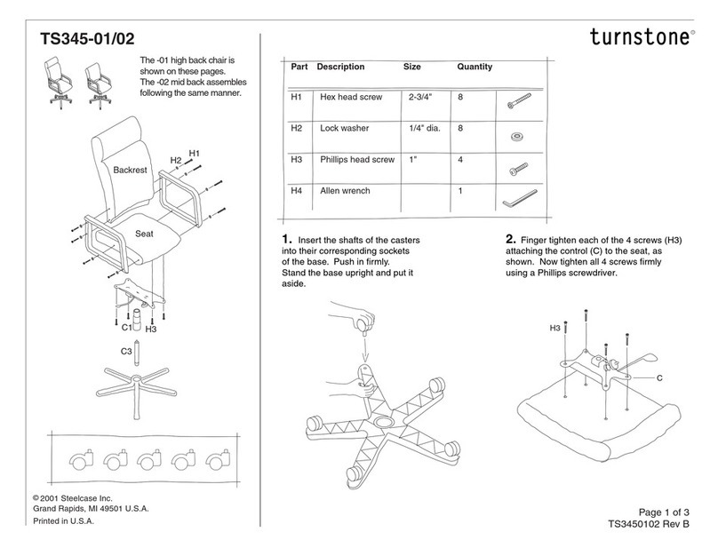
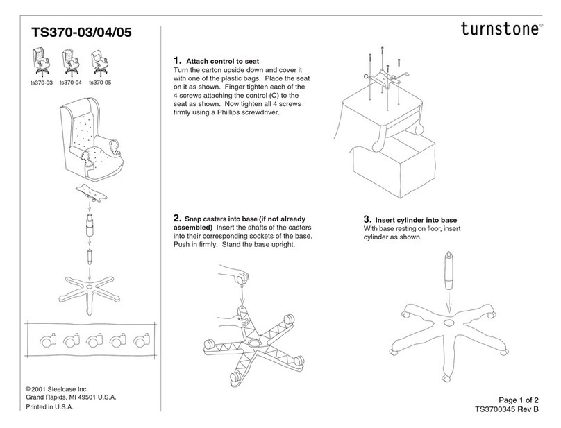
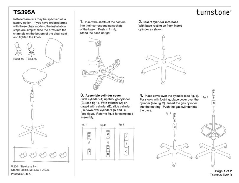
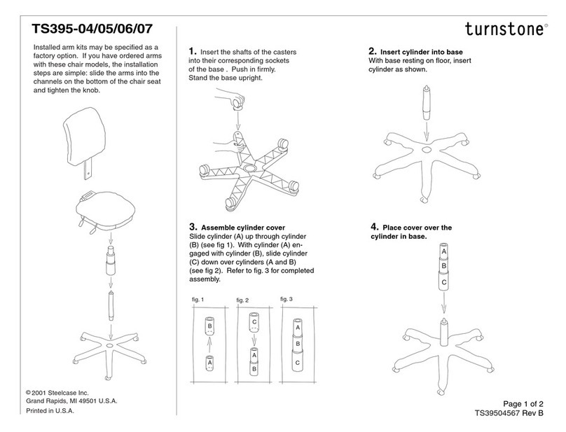
manuals.online logo
Brands
  1. Home
  2. •
  3. Brands
  4. •
  5. Turnstone
  6. •
  7. Indoor Furnishing
  8. •
  9. Turnstone Crank User manual

Turnstone Crank User manual

Page 1 of 30
939501205 Rev A
Crank Adjustable Units
Please identify the unit before selecting what section to follow
for assembly of product.
R
©2002 Steelcase Inc.
Grand Rapids, MI 49501 U.S.A.
Printed in U.S.A.
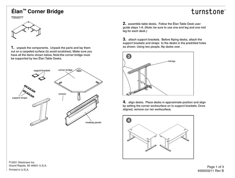
Extension Link Units with Standard Corner Units
Bilevel Corner Unit
Straight and Corner Units
Right
Extension
Left
Extension
Extension Link Units with Bilevel Corner Units
Section A
(begins on page 2)
Section B
(begins on page 7)
Section C
(begins on page 11)
Section D
(begins on page 21)
Right
Extension
Left
Extension
Extended
Both Sides
NOTE: Extension Units
are to be ordered separately
Extended
Both Sides
NOTE: Extension Units
are to be ordered separately
5 mm
Page 2 of 30
939501205 Rev A
Crank Handle
(Qty. 1)
Short Mounting
Screw
(Qty. 8)
Worksurface
Screw
(Qty. 6)
Foot Bolt
(Qty. 4)
Section A: Assembly instructions to assemble the following units:

45mm
5mm
Page 3 of 30
939501205 Rev A
Front
1. Flip the base upside down and without
cutting the tie wraps, put the feet on.
FOOT BOLTS
5
(optional)
Page 4 of 30
939501205 Rev A
Straight Standard
Corner Standard
2. Install grommet (black) into laminated
side of worksurface.

3. Install guide (white) into grommet.
4. Cut the tie wraps.

5. (Optional for STANDARD
units only) Install the "nut", "washer"
and "disk" to the gas cylinder (if not
already installed). Place gas cylinder
as shown.

NOTE: DO NOT attempt to screw or
compress the gas cylinder into place.

CAUTION: Cylinder under compression!
To avoid possible injury when servicing
cylinder, raise worksurface to uppermost
position and remove worksurface prior to
removing mounting plate. This will minimize
compression in the cylinder and facilitate
its removal.
2
3
GAS
CYLINDER
WASHER
NUT
DISK
Page 5 of 30
939501205 Rev A
Worksurface Screws
Standard Corner
Standard Straight
Rear
Front
Rear
Front
6. Place the worksurface on a protected
surface. Attach mounting plates on
worksurface, at the screw locations shown,
after aligning the pilot holes.
Page 6 of 30
939501205 Rev A
Corner Standard
Short Mounting Screws
Straight Standard
7
10
11
8
NOTE: If unit is placed with a gas
cylinder, adjust the unit to full height of
travel using crank handle.

7. Flip base upside down on a protected
surface.

NOTE: If base has gas cylinder, be
careful when inverting the base.

8. Mount top to base with short mounting
screws.

9. Flip unit to upright.

10. Remove Guides, retain for future
assembly.

11. Test: Using the crank handle, adjust
the unit to different heights to ensure unit
works properly.

Optional - if shrouds (ordered separately)
are installed in field.

12. Slide shroud over cross bars on
each leg of mechanism.

NOTE: To fully shroud the unit, repeat
this for both inside and outside of each
leg.
12
Page 7 of 30
939501205 Rev A
Crank Handle
(Qty. 1)
Short Mounting
Screw
(Qty. 8)
Worksurface
Screw
(Qty. 16)
Foot Bolt
(Qty. 4)
Section B: Assembly instructions to assemble the following units:

5mm 45mm
Page 8 of 30
939501205 Rev A
Front
1. Flip the base upside down and without
cutting the tie wraps, put the feet on.
FOOT BOLTS
Page 9 of 30
939501205 Rev A
Corner Bilevel
2. Install grommet (black) into laminated
side of worksurface.

3. Install guide (white) into grommet.
4. Place the worksurface on a protected
surface. Attach mounting plates on
worksurface.
23
Worksurface
Screws
Bilevel Corner
Rear
Front
Page 10 of 30
939501205 Rev A
6
9
10
7
5. Cut tie wraps.

6. Flip base upside down on a protected
surface.

7. Mount top to base with short mounting
screws.

8. Flip unit to upright.

9. Remove Guides, retain for future
assembly.

10. Test: Using the crank handle, adjust
both the front and the rear surfaces of the
unit to different heights to ensure unit
works properly.

Optional - if shrouds (ordered separately)
are installed in field.

11. Slide shroud over cross bars on
each leg of mechanism.

NOTE: To fully shroud the unit, repeat
this for both inside and outside of each
leg.
Corner Bilevel
Short Mounting Screws
11
Page 11 of 30
939501205 Rev A
Crank Handle
(Qty. 1)
Short Mounting
Screw
(Qty. 12 max)
Tie Strap
(Qty. 2 max)
Connector Plate
(Qty. 2 max)
Worksurface
Screw
(Qty. 12)
Spacer
(Qty. 1)
Foot Bolt
(Qty. 8 max)
Section C: Assembly instructions to assemble the following units:

5mm
Long Mounting
Screw
(Qty. 4)
Strap
Screw
(Qty. 8 max)
5mm
Connector
Plate Screw
(Qty. 16)
45mm
Page 12 of 30
939501205 Rev A
Front
1. Flip the base upside down and without
cutting the tie wraps, put the feet on.
FOOT BOLTS
NOTE: The large crossbar MUST
be in front for Standard Unit.
5
(optional)
Page 13 of 30
939501205 Rev A
Corner Standard
2. Install grommet (black) into laminated
side of worksurface.

3. Install guide (white) into grommet.
4. Cut the tie wraps.

5. (Optional for STANDARD)
Install the "nut", "washer" and "disk"
to the gas cylinder (if not already
installed). Place gas cylinder as shown.

NOTE: DO NOT attempt to screw or
compress the gas cylinder into place.

CAUTION: Cylinder under compression!
To avoid possible injury when servicing
cylinder, raise worksurface to uppermost
position and remove worksurface prior to
removing mounting plate. This will minimize
compression in the cylinder and facilitate
its removal.
2
3
GAS
CYLINDER
WASHER
NUT
DISK
Page 14 of 30
939501205 Rev A
8
7
8
Connector Plate
Connector Screw
Make sure the recessed holes are
facing away from the worksurface
at the holes that align with the
worksurface pilot holes.
6. Flip worksurface over on a protected surface.
Attach connector plates to corner worksurface.
7. Loop chain over sprocket making sure that
the extensions must have the crossbars to the front.

NOTE: Do not pull the chain in any direction as
this could affect the height of the base.

8. Cut tie wraps.

NOTE: The front of the feet must be pointed
towards the inside of workstation.

9. FOR UNITS EXTENDED ON BOTH SIDES:
Repeat the above 2 steps to attach the other
extended link.
Page 15 of 30
939501205 Rev A
10. Adjust the extension links so as to align
the slots.
Align
Page 16 of 30
939501205 Rev A
11. Install gas cylinder into open column of
extension bases.

NOTE: DO NOT attempt to screw in or compress
the gas cylinders into place.
CAUTION: Cylinder under compression! To avoid
possible injury when servicing cylinder, raise
worksurface to uppermost position and remove
worksurface prior to removing mounting plate. This
will minimize compression in the cylinder and
facilitate its removal.
GAS
CYLINDER
WASHER
NUT
DISK
optional
necessary
optional
necessary
necessary
Page 17 of 30
939501205 Rev A
Standard Unit
Extended on Both Sides
long
short
NOTE: No spacer needed
for extended on both sides
units.
Align
12. Place the long mounting screw into
the slots to prevent detachment of the
extensions.

13. Crank the unit using the crank
handle to top of travel. Make sure that
the gas cylinder sits BELOW the top
surface.

14. Attach standard mounting plates at
base/extension junction (one location for
extended, two locations for units
extended on both sides). Use long
mounting screws in the front and short
mounting screws in the back. Leave
screws loose.
14
13
12
Page 18 of 30
939501205 Rev A
15. (For single side Extended units
only) Place spacer as shown in one
location only - on non extended side to
ensure a level surface.

NOTE: Only one spacer needed per
assembly of single side extended unit.
Standard Unit
Extended Only
Right-Extended Unit
short
long
Never place a spacer
on the extension base.
Page 19 of 30
939501205 Rev A
16. Attach the mounting plates on the extensions using short
mounting screws. Leave screws loose.

17. Check if the unit is leveled at this point by measuring the
distance from the foot to the mounting plate. If not leveled then
undo steps 7 - 15 of this section. Pull chain of extension unit to
required height and redo steps 7 - 15 of this section.

18. Using the crank handle, crank and rotate several times to
ensure that the unit adjusts properly. Otherwise, remove
mounting plates, and redo step 17.
19. Place and install corner worksurface.

20. Mount top to base with worksurface screws
at the specified holes by aligning the mounting
plate holes to the worksurface pilot.
Standard Unit
Extended on Both Sides
short
mounting
screws
16
19
20
FOR STANDARD UNITS
WORKSURFACE SCREW
REAR
FRONT
Page 20 of 30
939501205 Rev A
26
24
Strap Screw
Worksurface Screw
21. Place extension surface onto connector
plates.

22. Attach connector plates with connector
plate screws.

23. Attach the strap using strap screws.

24. Rotate extension base slightly to line up
with the three pilot holes on the extension top
and drive worksurface screws.

25. Tighten all loose mounting plate screws.

26. Remove guides, retain for future
assembly.

27. Insert crank and rotate several times to
ensure that the unit adjusts properly.
TIP:
Level the extension with the base by
measuring the height from floor(or top of foot
casting). If not levelled, remove worksurface by
undoingall the worksurface screws; undo steps
to remove mounting plates, pull
chain to adjust height. Repeat measurement
above, do steps to attach mounting plate and
worksurface.

Optional - if shrouds (ordered separately) are
installed in field.

28. Slide shroud over cross bars on each leg
of mechanism.

NOTE: To fully shroud the unit, repeat this for
both inside and outside of each leg.
28

Other Turnstone Indoor Furnishing manuals

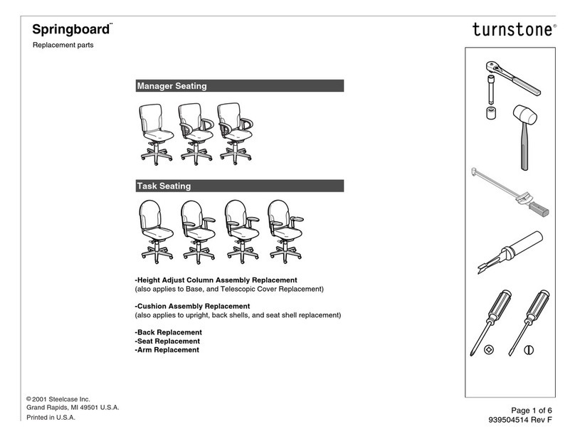
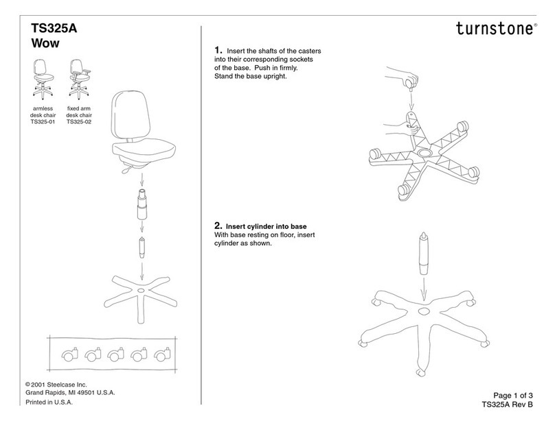
Turnstone Wow TS325 Series User manual

Turnstone

Turnstone Wow TS325 Series User manual

Turnstone TS 300A User manual

Turnstone

Turnstone TS 300A User manual

Turnstone Surprise TS305 User manual

Turnstone

Turnstone Surprise TS305 User manual

Turnstone Bassline OTTOMAN User manual

Turnstone

Turnstone Bassline OTTOMAN User manual

Turnstone Bivi Trunk User manual

Turnstone

Turnstone Bivi Trunk User manual

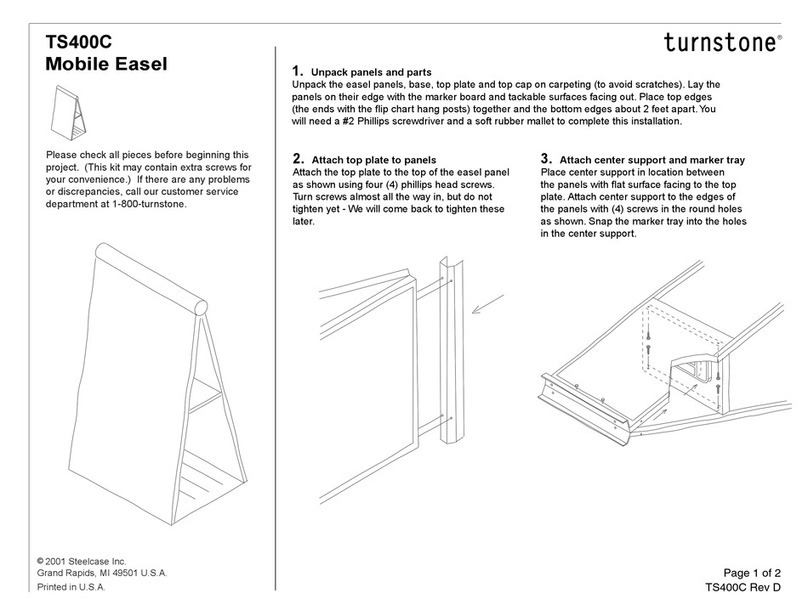
Turnstone TS400C User manual

Turnstone

Turnstone TS400C User manual

Turnstone Bivi User manual

Turnstone

Turnstone Bivi User manual

Turnstone TS345-01 User manual

Turnstone

Turnstone TS345-01 User manual

Turnstone TS 400A User manual

Turnstone

Turnstone TS 400A User manual

Turnstone TS395-02 User manual

Turnstone

Turnstone TS395-02 User manual

Turnstone Bivi Straight Screen User manual

Turnstone

Turnstone Bivi Straight Screen User manual

Turnstone Springboard User manual

Turnstone

Turnstone Springboard User manual

Turnstone TS345B User manual

Turnstone

Turnstone TS345B User manual

Turnstone TS370-03 User manual

Turnstone

Turnstone TS370-03 User manual

Turnstone Elan TS52077 User manual

Turnstone

Turnstone Elan TS52077 User manual

Turnstone Tour Counter User manual

Turnstone

Turnstone Tour Counter User manual

Turnstone TS395-04 User manual

Turnstone

Turnstone TS395-04 User manual

Turnstone Jenny Lounge Chair User manual

Turnstone

Turnstone Jenny Lounge Chair User manual

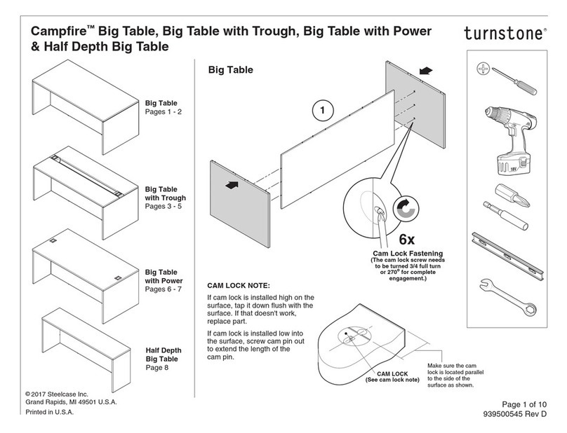
Turnstone Campfire User manual

Turnstone

Turnstone Campfire User manual
Turnstone Campfire User manual

Turnstone

Turnstone Campfire User manual

Turnstone TS395-12 User manual

Turnstone

Turnstone TS395-12 User manual

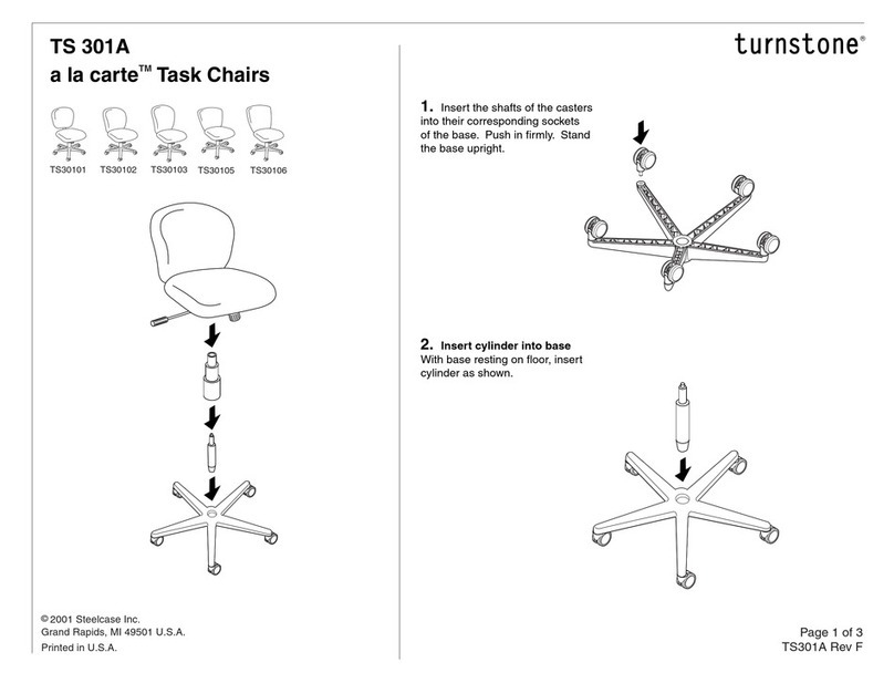
Turnstone A la carte TS 301A Series User manual
Turnstone

Turnstone A la carte TS 301A Series User manual

Turnstone Crew Task Chair User manual

Turnstone

Turnstone Crew Task Chair User manual
Popular Indoor Furnishing manuals by other brands

NRS Healthcare L97729 User instructions

NRS Healthcare

NRS Healthcare L97729 User instructions

Leggett & Platt Premium Models Series owner's manual

Leggett & Platt

Leggett & Platt Premium Models Series owner's manual

Next Claro 347876 Assembly instructions

Next

Next Claro 347876 Assembly instructions

Wholesale Interiors BBT 5264 Assembly instructions

Wholesale Interiors

Wholesale Interiors BBT 5264 Assembly instructions

Stevens Tot mate TM2182R quick guide

Stevens

Stevens Tot mate TM2182R quick guide

Courtyard Creations KTS6918 Assembly instructions

Courtyard Creations

Courtyard Creations KTS6918 Assembly instructions

Robern PUSH-TO-OPEN KIT installation instructions

Robern

Robern PUSH-TO-OPEN KIT installation instructions

DHP Hayley 5507096 manual

DHP

DHP Hayley 5507096 manual

Ditre Italia MONOLITH Assembling instructions

Ditre Italia

Ditre Italia MONOLITH Assembling instructions

E.N.Z. Engineering Ricoo FS0112 Assembly instructions

E.N.Z. Engineering

E.N.Z. Engineering Ricoo FS0112 Assembly instructions

velda 4i instructions

velda

velda 4i instructions

Whittier Wood 1200AFVCL Assembly instructions

Whittier Wood

Whittier Wood 1200AFVCL Assembly instructions

Coaster Heather 115141 Assembly instructions

Coaster

Coaster Heather 115141 Assembly instructions

Natural Signature VIRGINIA 25-4613T Assembly instructions

Natural Signature

Natural Signature VIRGINIA 25-4613T Assembly instructions

ASM FLY 23 FL 30 Assembly instructions

ASM

ASM FLY 23 FL 30 Assembly instructions

Coaster 193801 Assembly instructions

Coaster

Coaster 193801 Assembly instructions

U-Line H-3768 manual

U-Line

U-Line H-3768 manual

Birlea BROOKLYN FABRIC 4 Assembly instructions

Birlea

Birlea BROOKLYN FABRIC 4 Assembly instructions

manuals.online logo
manuals.online logoBrands
  • About & Mission
  • Contact us
  • Privacy Policy
  • Terms and Conditions

Copyright 2025 Manuals.Online. All Rights Reserved.