lower splash guard or skid plate, (Fig 1).
STEP 2
Place blocks or jack stands under the bumper to support it during
mounting bolt removal. Once the bumper has been safely
supported, remove the factory hardware attaching the bumper to
the end of the frame and remove the bumper assembly, (Figures
3A, 3B &4). WARNING!Assistance is required to hold the bumper
in place during hardware removal to prevent bumper from falling.
STEP 1
Remove the license plate from the bumper, (Figure 1). Next,
unplug the license plate lights, trailer plug and main wire harness.
NOTE: Bumper is designed to be compatible with larger 7-wire
universal trailer harness plug only.
PROCEDURE: REMOVE CONTENTS FROM BOX. VERIFY ALL PARTS
ARE PRESENT. READ INSTRUCTIONS CAREFULLY BEFORE
STARTING INSTALLATION. BUMPER IS HEAVY, ASSISTANCE IS
RECOMMENDED TO AVOID POSSIBLE INJURY OR DAMAGE TO THE
VEHICLE. IMPORTANT: OEM BUMPER REINFORCEMENT USED WITH
“STANDARD” TOW PACKAGE WITHOUT RECEIVER HITCH CANNOT
BE REINSTALLED. OE INTEGRATED “HD” HITCH, “MAX DUTY”
HITCH AND MOST AFTERMARKET RECEIVER HITCHES REQUIRED
FOR TOWING.
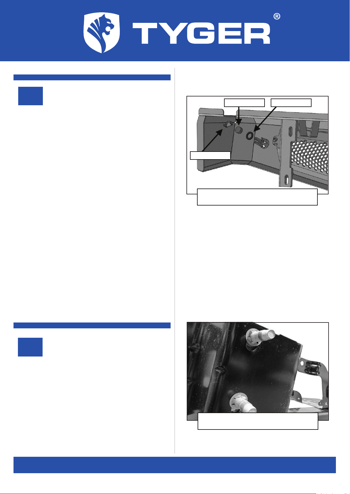
STEP 3
Unplug and remove sensors, (if equipped), from bumper. Next,
remove the license plate lights, spare tire access lock, (if
equipped) and trailer plug, (Figure 2). Release the wiring harness
from the clips attached to the back of the bumper. Move wire
harness away from bumper.
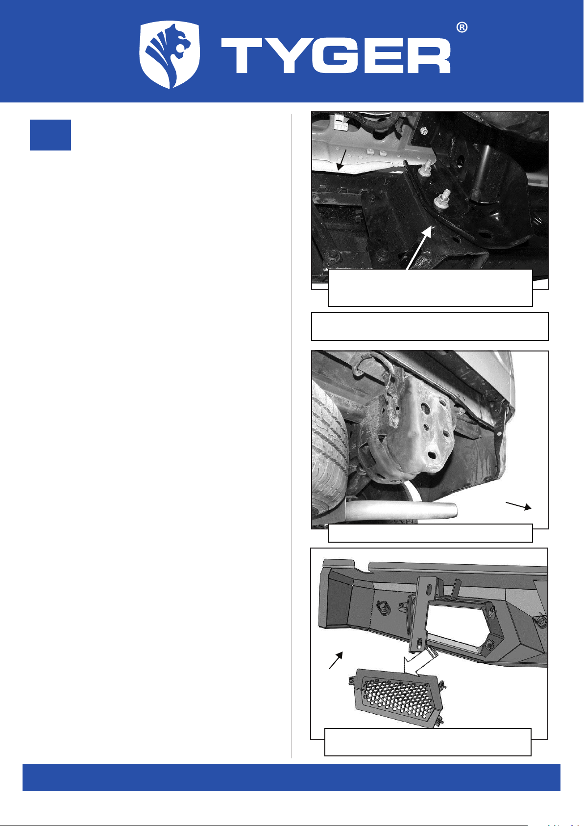
Remove the (3) factory hex nuts
attaching bumper assembly to frame
Rear
(Fig 3A) Note bumper with integrated receiver
hitch
Customer Support: www.TygerAuto.com/Contact
2/7
(Fig 1) Unplug and remove 7-wire trailer plug
Rear
(Fig 2) Unplug license plate lights
WARNING! Do not crawl under bumper unless the bumper is
properly supported on blocks or stands or the bumper may fall.