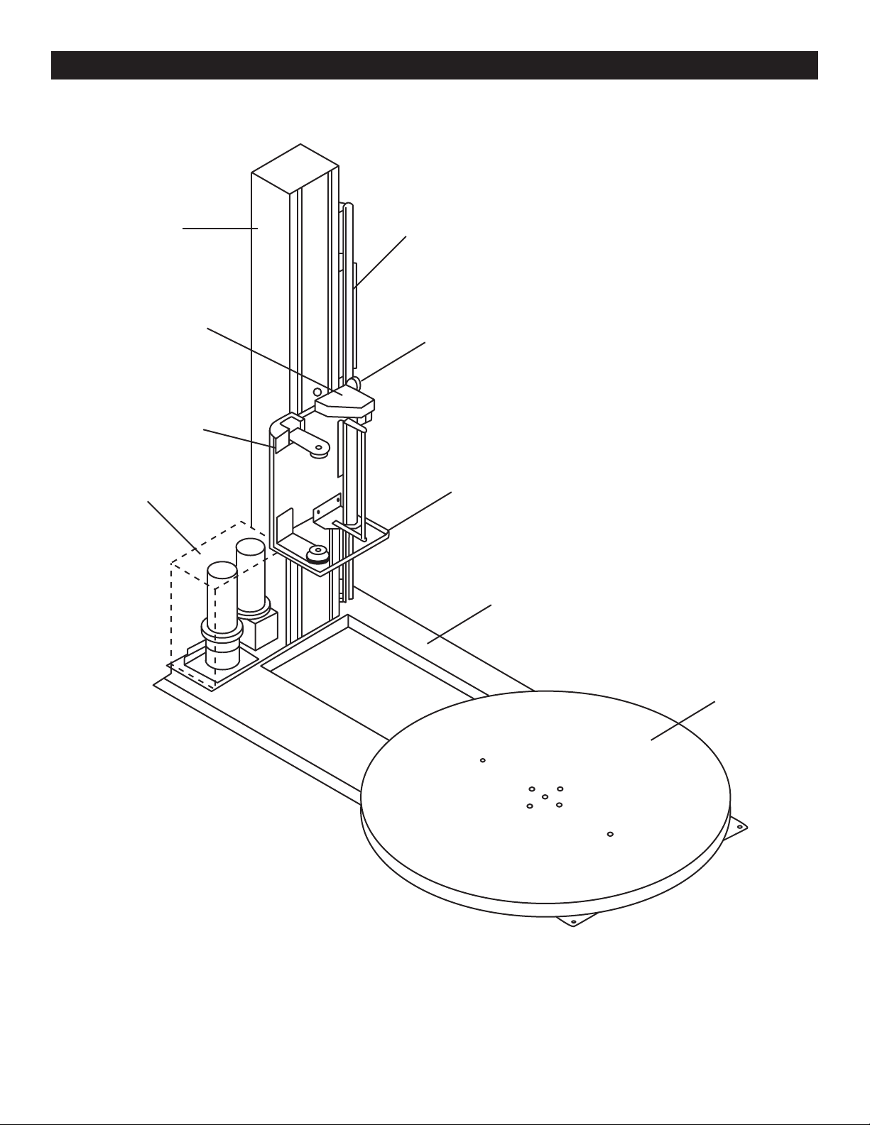
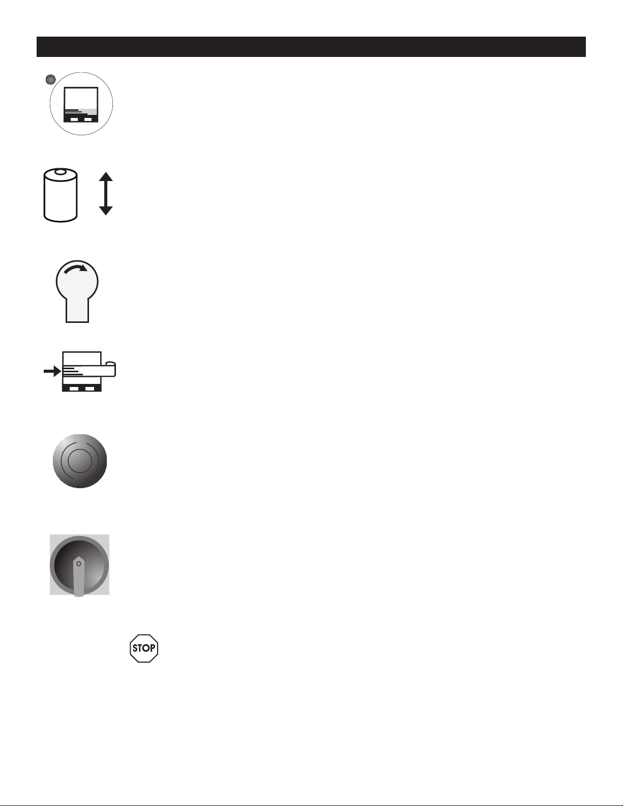
U-Line H-1675 User manual

0813 IH-1675PAGE 1 OF 11
πH-1675
110 "AutomAtic
stretcH wrAp
dispenser
1-800-295-5510
uline.com
SYSTEM SPECIFICATIONS
MACHINE DIMENSIONS
Length 99"
Width 60"
Height 129"
Turntable Diameter 59"
Turntable Height from Floor 3"
Wrapping Height 110 "
Operation Space 99 x 60 x 129"
Maximum Load Size 52 x 52 x 110"
Approximate Shipping Weight 1,250 lbs
ELECTRICAL SPECIFICATIONS
115 VAC, 60 Hz, Single-phase, 15 AMP
TURNTABLE SYSTEM
20 loads per hour (spiral)
12 RPM turntable maximum speed
4,000 lbs turntable maximum load capacity
FILM CARRIAGE / ELEVATOR SYSTEM
Adjustable raise and lower speeds
Automatic height detection photoelectric
sensor
FILM DELIVERY SYSTEM
Infinite / Manual Stretch Adjustment
10" Diameter Roll Capacity
20" Roll Width Capacity
CAUTION! Motor control equipment and
electronic controllers are connected to
hazardous line voltages. When servicing
drive and controllers, there may be exposed
components with housings or protrusions at or
above line potential. Extreme care should be
taken to protect against shock.
The user is responsible for conforming to all
applicable code requirements with respect to
grounding requirements. Do NOT use extension
cords to operate the equipment.
Disconnect AC input power before checking
components, performing maintenance,
cleaning up, and when the machine is not in
use. Do NOT connect or disconnect wires and
connectors while power is applied to circuit.
Wiring work should be performed only by
qualified personnel. There is a danger of
electric shock or fire.
WARNING! Loose clothing must NOT be worn
while the machine is in operation. Stay clear
of moving parts while the machine is running.

0813 IH-1675PAGE 2 OF 11
SYSTEM DESCRIPTION
Motor Box
Film Carriage
Stretch Handle
Tower Control Box
Tension Adjustment Knob
Foot Safety Bar
Seat
Turntable

0813 IH-1675PAGE 3 OF 11
SYSTEM SET-UP
MACHINE PLACEMENT
Place the Automatic Stretch Wrap Machine close to
an area where you will be wrapping your pallet loads.
Make sure that there is sufficient room to load/unload
the machine and that you do not stretch the wiring
cable. Remember, you will need to provide electrical
service to a 120 VAC, 15-AMP outlet.
FLOOR WEIGHT BEARING TOLERANCE
The floor must be able to bear the weight of the
machine, the weight of the maximum load, plus a
safety factor. The floor must also be able to tolerate
the stress of the machine’s operation. If fork trucks
will operate on the same weight bearing area, add
the weight of the trucks to the weight bearing stress
tolerance requirements.
MACHINE SET-UP
1. Place skidded machine close to the designated
wrap area. Remove all shipping fasteners holding
the machine to the pallet. The machine may be
crated with the tower tilted down with the motor
cover front carriage roller removed for shipping
purpose.
2. Place forks of the forklift through the tubes provided
at the rear base of the module, remove the
machine from these skids, and place it at the
designated wrap area.
3. If the OPTIONAL ramp (H-1071) is purchased:
Select a ramp position as illustrated below. The
ramp can be positioned anywhere in a 180° rotation
around the front of the turntable. There should be a
1/4"gap between the turntable and the ramp. The
ramp should be fully supported by the floor.
(See Figure 1)
1/4" Gap
180˚
Figure 1

0813 IH-1675PAGE 4 OF 11
1. The H-1675 will arrive with similar crating to what is shown
to the right. Please remove the protective packaging and
prepare the unit to stand up. (See Figure 2)
2. Once the machine has been successfully uncrated, the
next step is to begin erecting the tower. Start by leaning
the tower until fully upright. (See Figure 3)
CAUTION: Heavy Materials! Two or more
people are required for assembly.
3. Align the 5 bolts in the threaded inserts and tighten
completely. Next, the carriage will need to be
mounted to the tower. (See Figure 4)
CAUTION: Always have one or more people
supporting the tower while tightening bolts.
4. To mount the carriage, start by removing the bottom
4 bolts from the carriage mount bracket. (See Figure 5)
ASSEMBLY INSTRUCTIONS
Figure 2
Figure 3
Figure 4
Figure 5

0813 IH-1675PAGE 5 OF 11
TURNTABLE
ASSEMBLY INSTRUCTIONS CONTINUED
5. Loosen the top 2 bolts to hang the carriage in place.
(See Figure 6)
6. Align the top two bolts with slotted bolt holes at the top of
the carriage and hang in place. (See Figure 7)
7. The next step is to remount the photo sensor from its
protected shipping position. (See Figure 8)
8. Tighten up all 6 bolts on the back of the carriage.
(See Figure 9)
TURNTABLE
TURNTABLE
Figure 6
Figure 7
Figure 8
Figure 9

0813 IH-1675PAGE 6 OF 11
CONTROL BOX
TURNTABLE
SPEED
CARRIAGE
SPEED
START BANDING
BOTTOM
WRAPS
TOP
WRAPS
TURNTABLE
JOG
WRAP
MODES
SYSTEM
RESET
CARRAIGE
JOG
INFO

0813 IH-1675PAGE 7 OF 11
CONTROL BOX CONTINUED
LED DISPLAY
EO Emergency Stop Condition
- - System is normal
A Mode A Selected
B Mode B Selected
CO Continue operation by pushing START button
S System is in Manual
BUTTONS
WRAPPING MODE A - WRAP UP AND DOWN
The LED on the button’s upper left is on. In Mode A, the bottom wrap is applied first, and then
the top wrap follows. The film carriage comes down to its home position after wrapping cycle is
finished.
WRAPPING MODE B - WRAP UP ONLY
The LED on the upper left is on. In Mode B, after a bottom to top wrapping is completed, the
carriage stays on the top. The START button flashes at this point. To resume the operation, push
START. When the carriage reaches the bottom, the START button turns off. Push START button again
to begin a new cycle.
The TURNTABLE JOG button allows you to manually operate the turntable. When this button is
pushed, the light on the button’s upper left is on. Push START button to run the table. Pushing
the button again will stop the turntable and the light will turn off. This button may be used in
conjunction with the CARRIAGE JOG button.
The CARRIAGE JOG button allows you to manually operate the carriage. When this button is
pushed, one of the lights on the button’s upper right or left is on. The upper left light indicates
that the carriage will go up when the START button is pushed. Conversely, the upper right light
indicates the carriage will go down when the START button is pushed. To pause operation, simply
push this button again. Both indicator lights will go off. This button may be used in conjunction
with the TURNTABLE JOG button.
Push this RESET button, followed by the START button, to reset the system. The turntable will return to
its home position and the carriage will lower.
Push the TOP WRAPS button to select the number of top wraps desired (0 - 9).

0813 IH-1675PAGE 8 OF 11
CONTROL BOX CONTINUED
Push the BOTTOM WRAPS button to select the number of bottom wraps desired (0 - 9).
Turn the CARRIAGE SPEED adjustment knob clockwise to increase, and counterclockwise to
decrease the carriage speed. This allows you to adjust the overlap of your film.
Turn the TURNTABLE SPEED adjustment knob clockwise to increase, and counterclockwise to
decrease the turntable speed.
The BANDING button is used for applying multi-layer reinforcing wraps in automatic or manual
mode. Push and hold this button: the carriage will stop raising / lowering. When released, the
carriage will resume its movement.
The EMERGENCY STOP button stops the turntable in the event of emergency. This will NOT stop the
turntable instantly. The turntable will coast to a stop, depending on the load’s weight, after this
button is pushed.
This switches the main power ON or OFF.
WARNING! The FOOT SAFETY BAR, located underneath the film carriage works only when
the machine is ON. When the bar is activated, the main power will shut OFF. Releasing
the bar will reactivate the main power. Push START button to resume the operation.

0813 IH-1675PAGE 9 OF 11
MACHINE OPERATION
FILM LOADING
CAUTION! Be sure EMERGENCY STOP is pushed
in before threading the film and pulled out
when the film is threaded.
1. Place the film on the film mandrel.
2. Set the Stretch Handle to the OFF position to release
film tension.
3. Follow the Film Feed Diagram and thread the 6 foot
film tail ALL THE WAY through the rollers.
4. Set the Stretch Handle to the OFF position to release
film tension.
5. Rotate the Stretch Tension Adjustment
Knob clockwise to increase film tension or
counterclockwise to decrease film tension.
6. Attach the film securely to the pallet. Tying the end
of the film in a knot often helps secure the film to
the pallet.
NORMAL SYSTEM START-UP
1. Place the film on the film mandrel.
2. Set the Stretch Handle to the OFF position to release
film tension.
3. Thread the film as instructed and attach it to the
product.
4. Set the desired numbers for top and bottom wrap
counts.
5. Select wrapping mode A or B.
6. Press the START button to initiate cycle.
STOP CONDITION
1. In the event of an emergency, press the STOP
button. This cancels the current wrapping cycle
and immediately stops the system. The turntable will
coast to a stop.
2. Correct the problem
3. Pull the STOP button out and perform normal system
start-up procedure.
NOTE: After pressing the STOP button, wait for
at least 60 seconds before pulling the button
back out. This will allow the microcontroller
card to completely turn off.
APPLYING REINFORCEMENT WRAPS
1. Press the START button as normal to initiate cycle.
2. As the carriage travels up, press and hold the
BANDING button. The carriage will stop and
reinforcing wraps will be applied.
3. Letting go of the BANDING button will resume the
cycle.
LESS
STRETCH
50
0100
MORE
OFF
ON
Stretch Tension
Adjustment Knob
Film Feed
Diagram
Stretch Handle
(Off Position)
Stretch Tension
Indicator
Figure 10

0813 IH-1675PAGE 10 OF 11
SELF-TEST PROCEDURE
An operator may check the status of the machine
by running a self-test. If the procedure is carried out
properly, the INFO screen will display the location of the
problem(s).
To run the self-test, follow the procedure below:
1. Turn the turntable and carriage speed adjustment
knobs to maximum (clockwise) position.
2. Put a load on the turntable (about 3 feet tall).
3. While holding down the TURNTABLE JOG and
CARRIAGE JOG buttons, turn the main disconnect
switch ON.
4. Release the buttons after the screen shows “EE”.
5. Push the START button. The machine will run the test,
which takes approximately 2 minutes.
6. The screen will display the alarm code. Refer to the
table below for code information.
A1
F1
E1
G1
B1
C1
D1
B2
A2
C2
DISPLAY POSSIBLE PROBLEM LOCATION(S)
A1 Film carriage Safety Bar
EMERGENCY STOP button
Electrical enclosure safety switch
B1 Film carriage max upper limit switch
C1 Film carriage max down limit switch
D1 Turntable count/home proximity switch
E1 BANDING push button
F1 START push button
G1 Package height photo sensor
A2 START light
B2 Turntable motor
C2 Carriage motor

0813 IH-1675PAGE 11 OF 11
TROUBLESHOOTING
WARNING! Make sure that only qualified
personnel perform inspection, troubleshooting
and part replacement.
CAUTION! Disconnect all power, including
external control power that may be present,
before servicing the frequency drive
controllers. WAIT for three (3) minutes for the
DC bus capacitors to discharge. The
frequency drive controller’s display and/or
LEDs are not accurate indicators of the
absence of DC bus voltage.
OPERATING ISSUE CAUSES RECOMMENDATIONS
Machine not powering on. Main power is turned off. Check that power is going to the machine. Verify that switch
is turned on.
Machine not plugged into 120VAC outlet. Verify the voltage going to the machine matches the power
supply labels on the power module.
Power supply faulty.
Internal battery not charged.
Film carriage foot engaged. Remove obstruction from Film Carriage foot.
Film carriage malfunctioning. FILM CARRIAGE SPEED dial not set high
enough.
Adjust potentiometer towards 100% to set speed.
Resistance of potentiometer not equal to
5K_ across.
Tighten wiring, replace dial if necessary.
The carriage limit switch lever arm is
obstructed.
Remove obstruction and/or clean limit switch head.
Microcontroller card inside electrical
enclosure not turned on.
Check and switch on the main circuit breaker.
Turntable is malfuntioning. Turntable speed potentiometer dial not
set high enough.
Adjust potentiometer towards 100% to set speed.
Resistance of potentiometer not equal to
5K_ across.
Tighten wiring, replace dial if necessary.
Microcontroller card inside electrical
enclosure not turned on.
Check and switch on main circuit breaker.
The turntable motor is not running. Tighten or replace motor wiring as necessary.
Check turntable for mechanical restrictions.
Replace microcontroller or turntable output relav.
π CHICAGO • ATLANTA • DALLAS • LOS ANGELES • MINNEAPOLIS • NYC/PHILA • SEATTLE • MEXICO • CANADA
1-800-295-5510
uline.com
Table of contents
Other U-Line Dispenser manuals

U-Line
U-Line H-878 User manual

U-Line
U-Line H-1130 User manual

U-Line
U-Line SLIMFOLD H-4701 User manual

U-Line
U-Line H-1119 User manual

U-Line
U-Line H-725 User manual

U-Line
U-Line TORK H-7859 User manual

U-Line
U-Line KLEENEX REVEAL H-7855 User manual

U-Line
U-Line PURELL H-10644 User manual

U-Line
U-Line PURELL ES6 User manual

U-Line
U-Line Rubbermaid H-3542 User manual

U-Line
U-Line CDE224E User manual

U-Line
U-Line H-9504 User manual

U-Line
U-Line H-70657 User manual

U-Line
U-Line H-1585 User manual

U-Line
U-Line Tork Xpressnap H-5858 User manual

U-Line
U-Line H-1585 User manual

U-Line
U-Line H-28 User manual

U-Line
U-Line TORK XPPESSNAP User manual

U-Line
U-Line H-878 User manual

U-Line
U-Line H-1132 User manual