U-Line Uline User manual

0415 IH-959PAGE 1 OF 6
POWER
RESET FEED
LENGTH
2
0
3
4
5
MAX
M
ON
OFF
TECHNICAL DATA
Strapping Speed: 2.5 Seconds/Strap
Dimensions: 35½" L x 23" W x 30½" H
Net Weight: 220 lbs.
Max. Tension: 100 lbs.
Strap Width: 1/4" – 5/8"
Core Capacity: Uses 8 x 8", 9 x 8" or 11 x 8"
(Core Dia. x Width)
Safety Switch: Stops machine when top is lifted.
Power: 110 VAC, 50/60 Hz, Single phase.
MACHINE SETUP
POWER
RESET
FEED
LENGTH
GNIPPARTS ETUORLEER DAO
L
1
2
Slide Roller
BAND GUIDE
Roller
Remove adapter
before installing
reel.
Right Side
H-959
POLYPROPYLENE
STRAPPING MACHINE
Para Español, vea páginas 5-8.
1. Remove plastic reel from machine. It comes preset
for 9" core. Remove outer ring adapter for 8" core. For
11" strapping core, the H-959-TC075 adapter can be
purchased. (See Figure 1)
2. Load Strapping onto reel. DO NOT REMOVE BANDING UNTIL
LOADED. Make sure strap is going in correct direction
indicated by red arrow. (See Figure 1)
1. Pull slide roller bar down and thread strapping over (1)
and under (2). Thread strap through guide (Ref 10) until it
reaches top of machine. (See Figure 2)
Open lid and remove contents from tray. Install package guide on lid.
Figure 1 Figure 2

0415 IH-959PAGE 2 OF 6
OPERATION INSTRUCTIONS
1. Set strap feed length: Determine the length of strap
needed. Set control for 0-6. Lengths listed in meters.
1 = 3 ft. of strap. Example: for 6 ft. of strapping, set the
control at "2". (See Figure 3)
2. Turn power ON. Allow machine to heat up 3-4 minutes.
Strap won’t seal if heating blade is not hot enough.
(See Figure 3)
3. Pre-feed the strap: Press and hold the FEED button until the
desired length of strap feeds out. (See Figure 3)
NOTE: Pre-feeding is only necessary after
installing a new strap coil or finishing a coil.
4. Strapping the package:
a. Place package on the machine against the package
guide. (See Figure 4)
b. Pass strap around package and insert the strap end
into the strap inlet to start the strapping tensioning
and heat sealing cycle. (See Figure 5)
c. Strap tensions, heat seals and cuts. Remove package.
d. Timer resets, strap feeds out and machine is ready for
the next package.
5. Turn power OFF.
MOTOR TIMER
The timer is located on the printed circuit box (PCB Box). If your
machine runs for a long time between packages, turn the
timer down. If the machine is used more frequently, turn the
timer up so the motor isn’t starting and stopping all the time.
(See Figure 6)
POWER
ON
MAX
M
0
1
2
3
4
5
OFF
LENGTH
RESET
FEED
RESETFEED
LENGTH
2
0
3
4
5
MAX
M
O
N
O
F
F
FUSE
MOTOR TIMER
110V/10A
220V/7A
FUSE
SECS60
50
40
30
20
10
0
REFERENCE
# DESCRIPTION
1 POWER SWITCH: TURNS MACHINE ON/OFF.
2 FEEDING LENGTH CONTROL: LENGTHS LISTED IN METERS.
3RESET BUTTON: COMPLETES CYCLE AND RETURNS MACHINE
TO "HOME" POSITION.
4 STRAP FEED BUTTON: RUNS OFF ANY LENGTH OF STRAP.
5PLUG: 110V
6 STRAP REEL: HOLDS STRAP COIL.
7 BRAKE: STOPS BAND REEL FROM OVER ROTATING.
8 STRAP GUIDE FOR BRAKE: STRAP THREADS THROUGH GUIDE.
9 STRAP BYPASS GUIDE: STRAP THREADS THROUGH GUIDE.
10 FEED GUIDE
11 STRAP INSERTION INLET: DETECTS LEADING EDGE OF STRAP TO
START TENSIONING/HEAT SEALING CYCLE.
POWER
RESETFEED
LENGTH
2
0
3
4
5
MAX
M
ON
OFF
1
2
34
5
7
8
9
11
6
10
Figure 3
Figure 5
Figure 6
Figure 4
Motor
Timer

0415 IH-959PAGE 3 OF 6
MAINTENANCE
CLEANING
After use, clean residue from top and bottom of heater blade
with Scotch-Brite™ Pad (S-11724). Brush until metal is bright.
• Remove heater cover. To remove blade, pull back on
spring-loaded arm. (See Figure 10) Lift blade assembly
up and forward to release. DO NOT LOOSEN SET SCREWS.
Reverse to reassemble.
Use Air Gun or ULINE Air In A Can (S-6771) to clean parts of
plastic residue. (See Figure 11)
LUBRICATION
Weekly (more often with high usage) – Apply a few drops of
10-20W machine oil to oiling points. (See Figure 11) Make sure
to clean dirt and debris from parts before applying oil.
ADJUSTMENTS
STRAP WIDTH
Make adjustments at the Strap Outlet and the Strap Inlet.
1. Machine comes preset for 1/2" strapping.
2. Strap Inlet: Loosen two black screws with Allen wrench. Set
the Strap Inlet guide about 1/16" wider than the strapping
you are using and align with the Strap Outlet. Retighten
socket screws. (See Figure 7)
3. Strap Outlet: Loosen two Phillips head screws. (See shaded
areas in Figure 6) Adjust the width to accept width of strap
you are using. Set the strap outlet guide at 1/2" for 1/4" and
3/8" strapping and 5/8" for 1/2" strapping. Retighten screws.
(See Figure 8)
TENSION ADJUSTMENT
1. The strap tension adjustment handle is located at the
back of the machine. (See Figure 9)
2. Machine comes preset at 0 tension. Recommend starting
at middle point of tension gauge bar.
3. Turn the handle clockwise to increase tension;
counterclockwise to decrease tension.
9 12
15
9
6
12
15
T
I
G
H
T
L
O
O
S
E
πCHICAGO • ATLANTA • DALLAS • LOS ANGELES • MINNEAPOLIS • NYC/PHILA • SEATTLE • MEXICO • CANADA
1-800-295-5510
uline.com
Figure 7
Figure 8
Figure 9
Figure 10 Figure 11
Strap Inlet
Strap Outlet
Tension
Adjuster
Blade
Assembly
Set
Screws
Clean
Blade
Spring Loaded Arm
Air and
Oiling Points

0415 IH-959PAGE 4 OF 6
POWER
RESET FEED
LENGTH
2
0
3
4
5
MAX
M
ON
OFF
DATOS TÉCNICOS
Velocidad de Flejado: 2.5 Segundos/Fleje
Dimensiones: 35½" Largo x 23" Ancho x 30½" Alto
Peso Neto: 220 lbs.
Tensión Máx.: 100 lbs.
Ancho del Fleje: 1/4" – 5/8"
Capacidad del Núcleo: Utiliza 8 x 8", 9 x 8" or 11 x 8"
(Diá. x Ancho)
Interruptor de Seguridad: La máquina para cuando
se levanta la tapa.
Potencia: 110 VAC, 50/60 Hz, Monofásica
INSTALACIÓN DE LA MÁQUINA
POWER
RESET
FEED
LENGTH
RUTA DEL FLEJE
CARGAR EL ROLLO
1
2
Rodillo de
Deslizamiento
GUÍA DE BANDA
Rodillo
Remueva el
adaptador antes
de instalar el rollo.
Lado
Derecho
H-959
MÁQUINA PARA FLEJE
DE POLIPROPILENO
01-800-295-5510
uline.mx
1. Remueva el rollo de plástico de la máquina. Viene
predeterminada para un núcleo de 9". Remueva el anillo
externo del adaptador para el núcleo de 8". Se puede
comprar el adaptador H-959-TC075 para el núcleo de 11"
del fleje. (Vea Diagrama 1)
2. Cargue el Fleje en el rollo. NO REMUEVA LA CINTA HASTA
QUE ESTÉ CARGADO. Asegúrese que el fleje vaya en la
dirección correcta indicada por la flecha roja. (Vea
Diagrama 1)
1. Jale la barra de deslizamiento hacia abajo y ensarte el
fleje por arriba (1) y abajo (2). Ensarte la correa por la
guía (Ref 10) hasta que llegue arriba de la máquina. (Vea
Diagrama 2)
Abra la tapa y remueva el contenido de la bandeja. Instale la guía del paquete en la tapa.
Diagrama 1 Diagrama 2

0415 IH-959PAGE 5 OF 6
INSTRUCCIONES DE FUNCIONAMIENTO
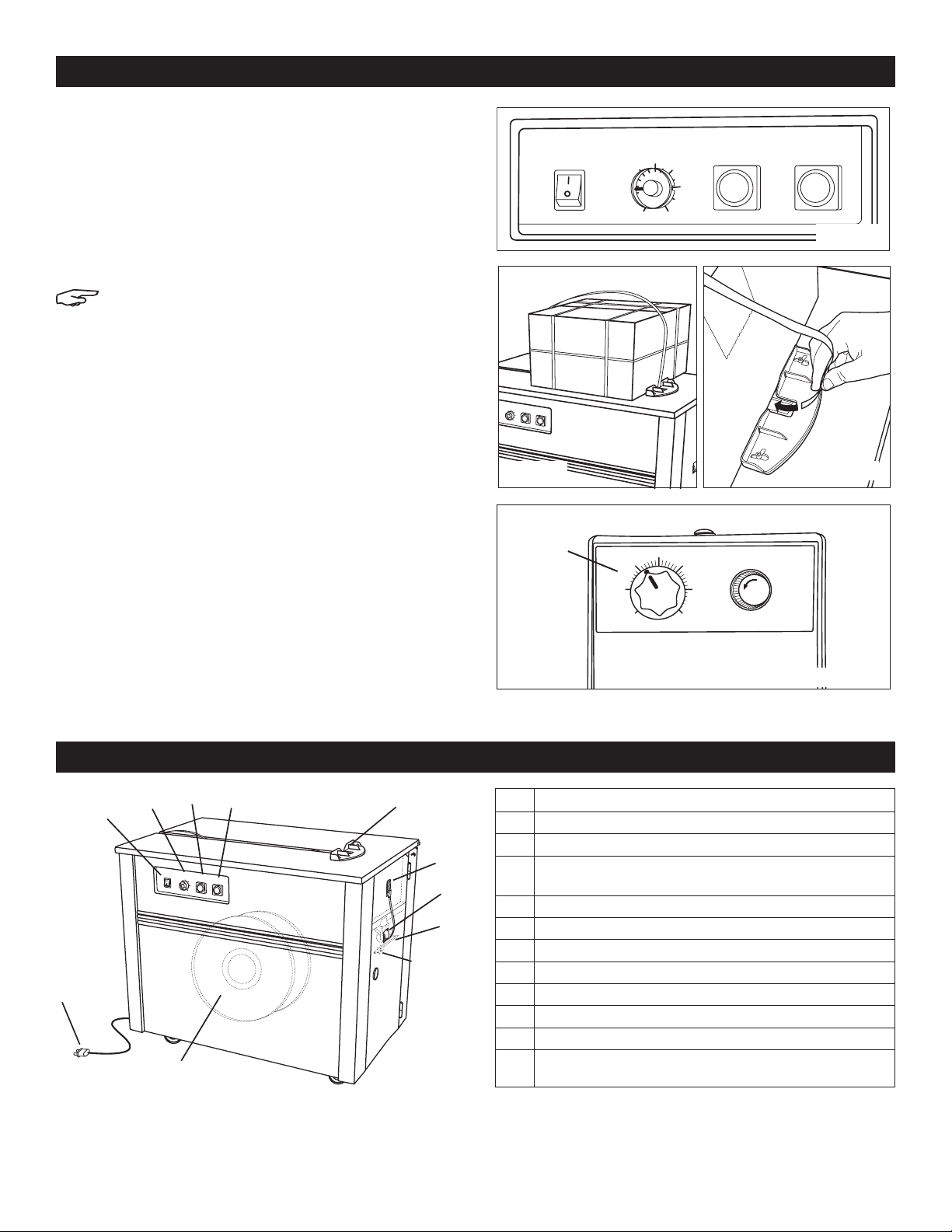
1. Para establecer la longitud del fleje: Determine la
longitud del fleje que necesita. Ajuste el control de 0-6.
Los largos se muestran en metros. 1 = 3 pies de fleje.
Ejemplo: para 6 pies de fleje, ajuste el control a "2". (Vea
Diagrama 3)
2. Presione el botón ON para encender. Permita que la
máquina se caliente de 3-4 minutos. El fleje no sellará
si la navaja de calentamiento no está suficientemente
caliente. (Vea Diagrama 3)
Pre-alimentación del fleje: Presione y
mantenga presionado el botón FEED hasta
que salga la longitud de fleje deseada.
3. Para flejar el paquete:
a. Coloque el paquete sobre la máquina junto a la guía.
(Vea Diagrama 4)
b. Pase el fleje alrededor del paquete e inserte el
extremo del fleje en el canal para empezar a
tensionarlo y comenzar el ciclo de sellado a calor.
(Vea Diagrama 5)
c. El fleje es tensado, sellado a calor y cortado. Remueva
el paquete.
d. El temporizador se reinicia, el fleje sale y la máquina
está lista para el siguiente paquete.
4. Presione el botón OFF para apagar.
TEMPORIZADOR DEL MOTOR
El temporizador se encuentra en la caja del circuito impreso
(Caja PCB). Si su máquina queda encendida por largo
tiempo entre cada paquete, gire el temporizador para dis-
minuir. Si la máquina es usada más frecuentemente, gire el
temporizador para aumentar, así el motor no estará iniciando
y parando todo el tiempo. (Vea Diagrama 6)
POWER
ON
MAX
M
0
1
2
3
4
5
OFF
LENGTH
RESET
FEED
RESETFEED
LENGTH
2
0
3
4
5
MAX
M
O
N
O
F
F
FUSE
MOTOR TIMER
110V/10A
220V/7A
FUSE
SECS60
50
40
30
20
10
0
REFERENCIA
# DESCRIPCIÓN
1 INTERRUPTOR: ENCIENDE (ON) O APAGA (OFF) LA MÁQUINA
2CONTROL PARA LA LONGITUD DEL FLEJE: LARGOS SE
MUESTRAN EN METROS.
3BOTÓN DE REINICIO: COMPLETA EL CICLO Y REGRESA LA
MÁQUINA A LA POSICIÓN INICIAL.
4BOTÓN DE ALIMENTACIÓN DEL FLEJE: DESPACHA CUALQUIER
LONGITUD DEL FLEJE.
5EN C H UFE: 110 V
6 RIEL PARA EL FLEJE: SOSTIENE EL ROLLO DEL FLEJE.
7 FRENO: DETIENE LA SOBREROTACIÓN DEL RIEL.
8GUÍA DEL FLEJE PARA EL FRENO: EL FLEJE SE ENGANCHA A
TRAVÉS DE LA GUÍA.
9GUÍA DE DESVIACIÓN DEL FLEJE: EL FLEJE SE ENGANCHA A
TRAVÉS DE LA GUÍA.
10 GUÍA DE ALIMENTACIÓN
11 CANAL DE INSERCIÓN DEL FLEJE: DETECTA LA PUNTA DEL FLEJE
PARA EMPEZAR A TENSIONAR/CICLO DE SELLADO A CALOR.
POWER
RESETFEED
LENGTH
2
0
3
4
5
MAX
M
ON
OFF
1
2
34
5
7
8
9
11
6
10
Diagrama 3
Diagrama 5
Diagrama 6
Diagrama 4
Temporizador
del Motor

0415 IH-959PAGE 6 OF 6
MANTENIMIENTO
AJUSTES
ANCHO DEL FLEJE
Haga ajustes en la salida del fleje y el canal del fleje.
1. La máquina viene predeterminada para fleje de 1/2".
2. Canal del Fleje: Afloje dos tornillos negros con una llave
Allen. Ajuste la guía del canal del fleje aproximadamente
1/16" más ancho que el fleje que usted esté utilizando y
alinee con la salida del fleje. Apriete los tornillos.
(Vea Diagrama 7)
3. Salida del Fleje: Afloje dos tornillos Phillips. (Vea las partes
sombreadas en el Diagrama 5) Ajuste la anchura para
que quepa el fleje que usted esté utilizando. Coloque la
guía de la salida del fleje a 1/2" para flejes de 1/4" y 3/8" y
a 5/8" para fleje de 1/2". Apriete los tornillos.
(Vea Diagrama 8)
AJUSTE DE LA TENSIÓN
1. La perilla de ajuste para la tensión del fleje está
localizada en la parte trasera de la máquina.
(Vea Diagrama 9)
2. La máquina viene predeterminada a tensión 0.
Recomendado que comience en el calibre medio de la
barra de tensión.
3. Gire la perilla en el sentido de las manecillas del reloj
para incrementar la tensión; en el sentido contrario de las
manecillas del reloj para reducir la tensión.
9 12
15
9
6
12
15
T
I
G
H
T
L
O
O
S
E
LIMPIEZA
Después del uso, limpie los residuos de arriba y abajo de la
navaja de calentamiento con la Fibra Limpiadora
Scotch-Brite™ (S-11724). Talle hasta que el metal brille.
• Remueva la cubierta del calentador. Para remover la
navaja, jale el brazo con resorte. (Vea Diagrama 10)
Levante el ensamble de la navaja y jale para soltarla. NO
AFLOJE LOS TORNILLOS DE AJUSTE. Para reinstalar proceda
de manera inversa.
Use una Pistola de Aire o ULINE Aire Comprimido (S-6771) para
limpiar las partes de residuos de plástico. (Vea Diagrama 11)
LUBRICACIÓN
Semanal (más frecuente para uso pesado) – Aplique unas
cuantas gotas de aceite de máquina 10-20W a los puntos
de lubricación. (Vea Diagrama 11) Asegúrese de limpiar la
suciedad y los residuos de las partes antes de aplicar el
aceite.
Diagrama 7
Diagrama 8
Diagrama 9
Diagrama 10 Diagrama 11
Canal del
Fleje
Salida del
Fleje
Ajustador de
Tensión
Ensamble
de la
Navaja
Limpieza de
Navaja
Brazo con Resorte
Puntos de Aire
y Lubricación
πCHICAGO • ATLANTA • DALLAS • LOS ANGELES • MINNEAPOLIS • NYC/PHILA • SEATTLE • MEXICO • CANADA
01-800-295-5510
uline.mx
Table of contents
Languages:
Other U-Line Packaging Equipment manuals

U-Line
U-Line H-1459 User manual

U-Line
U-Line H-1482 User manual

U-Line
U-Line H-528 User manual

U-Line
U-Line H-4025 User manual

U-Line
U-Line H-140 User manual

U-Line
U-Line H-2079 User manual

U-Line
U-Line S-1135 User manual

U-Line
U-Line H-5334 User manual

U-Line
U-Line S-15188 User manual

U-Line
U-Line Green Machine H-3518 User manual

U-Line
U-Line H-7242 User manual

U-Line
U-Line H-7241 User manual

U-Line
U-Line H-573 User manual

U-Line
U-Line H-109 User manual

U-Line
U-Line H-8254 User manual

U-Line
U-Line H-2079 User manual

U-Line
U-Line H-167 User manual

U-Line
U-Line Green Machine H-3518 User manual

U-Line
U-Line S-15179 User manual

U-Line
U-Line S-7344 User manual