UCS NANO DC User manual

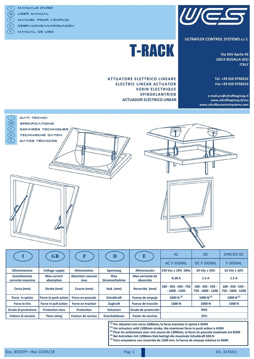
ULTRAFLEX CONTROL SYSTEMS s.r.l.
Via XXV Aprile 45
16012 BUSALLA (GE)
ITALY
Tel. +39 010 9768232
Fax +39 010 9768233
e-mail:ucs@ultraflexgroup.it
www.ultraflexgroup.it/ucs
www.ultraflexcontrolsystems.com
Doc. ... - Rev. 07/09/2018 Drw. / Dis. ....
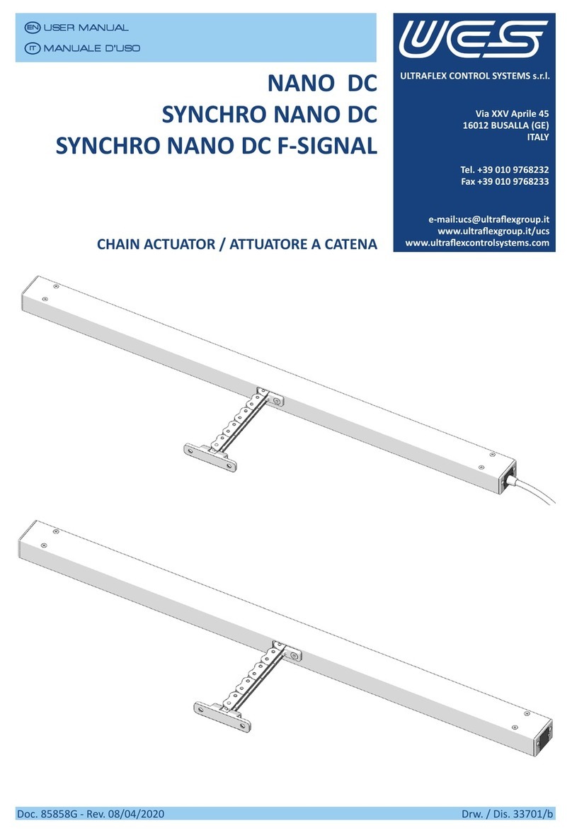
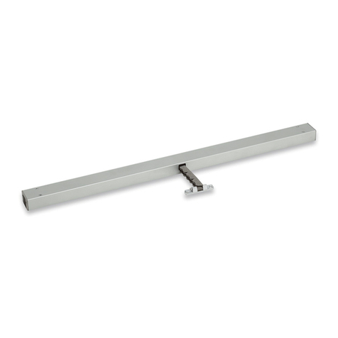
NANO DC
SYNCHRO NANO DC
SYNCHRO NANO DC F-SIGNAL
CHAIN ACTUATOR / ATTUATORE A CATENA
MANUALE D’USO
USER MANUAL
IT
EN


Doc. _____ - Rev. __/__/____
USER MANUAL
EN
Drw. / Dis. ....____3/45
MANUALE D’ISTRUZIONI
IT
CONTENTS INDICE
1. INTRODUCTION............................................4
1.1 Symbols used .........................................4
1.2 General safety rules ...............................4
1.3Informaveleer...................................6
2. PACKING CONTENTS.....................................7
2.1 Accessories not included .......................7
2.1.1 Bracket kits.....................................7
2.1.2 Cable kits........................................8
3. UNPACKING..................................................8
4. DATA PLATE ..................................................9
5. PRODUCT DESCRIPTION...............................9
6. TECHNICAL FEATURES ................................11
6.1 Models .................................................13
7. DIMENSIONS..............................................14
8. WIRING ......................................................15
8.1NANODCconnecon...........................15
8.1.1 NANO DC wiring diagram.............15
8.2 SYNCHRO NANO - SYNCHRO NANO
F-SIGNALconnecon ...........................16
8.2.1 SYNCHRO NANO wiring diagram
(singleactuatorconnecon)......16
8.2.2 SYNCHRO NANO F-SIGNAL wiring
diagram (single actuator
connecon) ................................16
8.2.3 Connection example (SYNCHRO
NANO DC-SYNCHRO NANO DC
F-SIGNAL ....................................17
8.2.4 Voltage drop for actuator chain .18
8.2.5 Cableconnecon .......................19
8.2.6 Customized cable wiring ............20
8.2.7 Specialapplicaons....................23
9. INSTALLATION ............................................24
9.1 Necessary tools....................................24
9.2 Top hung window open outwards - side
bracket with sill...................................25
9.3 Top hung window open outwards -
concealedinstallaon .........................27
9.4 Top hung window open outwards -
concealed wing with front bracket .....29
9.5 Top hung window open outwards - with
front bracket .......................................31
9.6 Boom hung window open inwards (Z
bracket+pivongbracket) .................33
9.7 Bottom hung window open inwards -
actuator on wing.................................36
9.8 Boom hung window open outwards -
concealedinstallaon .........................39
10. MAINTENANCE ..........................................42
11. CLEANING ..................................................42
12. DISPOSAL ...................................................42
13. WARRANTY ................................................43

Doc. _____ - Rev. __/__/____
USER MANUAL
EN
Drw. / Dis. .... ____
4/45
MANUALE D’ISTRUZIONI
IT
1.2 General safety rules ....
This manual is an integral part of NANO
actuators and it must be carefully read before
usingit since itgivesimportantindicaons
withregardstoitssafeinstallaon,useand
maintenance. Keep it with care.
BeforeusingNANOactuators,readcarefully
the following general safety rules.
Thisactuatorisonlyto be edon windows
that are out of reach of people.
Be very careful of moving parts during
installaontoavoidcrushing.
Boomhingedwindowsmustbeprovidedwith
side checks.
Priortoinstallaonmakesurethat:
• the actuator performances comply with
theesmatedapplicaon
• windowprolesandngsaresuitable
to the stresses caused by the actuator
• windowngs(hinges)andabsenceof
obstacles allow complete opening
• theexisngelectricsystemscomplywith
theregulaonsinforce
• power supply features are those indicated
intheactuatorspecicaons
• The declared nominal values do not
consideranywindstress:itisnecessary
to evaluate it correctly to avoid any
failureoftheactuatororofthewindow,
parcularlyincaseoflargewindows.
Unsuitableapplicaonorwronginstallaonmay
resultinalossofsystemoperangfunconsand
consequently in damages or/and injuries.
Before connecng the actuator to power
supplymakesureithasbeenturnedoto
avoidelectrocuon.
An omnipolar switch shall be provided in the
supplymains(accordingtoCEIEN60335-1).
In case the actuator is installed on a mobile
wing, make sure the supply cable is not
subjecttostresswhenoperang.
1 INTRODUCTION ....
The operations which can be dangerous
if they are not carried out correctly are
indicated with this symbol.
Danger to persons due to electricity.
The operaons whose execuon requires
qualied or specialized sta to avoid any
danger are indicated with this symbol.
Important information for a correct
installaonanduseoftheproduct.
Danger of hands crushing
1.1 Symbols used ....

Doc. _____ - Rev. __/__/____
USER MANUAL
EN
Drw. / Dis. ....____
5/45
MANUALE D’ISTRUZIONI
IT
When operating the actuator, follow the
instruconsbelow:
• prevent liquids from entering the
actuator
• do not approach moving parts unl
they have come to a complete stop
• at least once a year check at sight for
damages or wear in the supply cable
• do not carry out any intervention
on the actuator, do not remove or
disassemble parts of the actuator;
in case of malfunction or damaged
cablecontact“UCS-UltraexControl
Systems srl”
In case the window is accessible at a height
of2,5matleastprovidethesystemwithan
emergencyswitcho.Itisalsoadvisableto
installamaintainedcontactpush-buon.
Pay aenon when closing the window:
danger of crushing.
Any installaon and/or maintenance tasks
areonlytobecarriedoutbyskilled,specialist
personnel. Exisng electrical systems must
comply with the rules in force in the country
where the actuator is installed. Before doing
anymaintenance,makesurethatthepower
supply has been disconnected. Conform to
the wiring diagrams shown in this manual.
Thecabletypes,lenghtsandseconsmust
be choosen according to the technical
specicaonsprovidedbythemanufacturer.
Cables must be laid properly, so that
they cannot be cut, bent or twisted. It is
necessary to provide the cables laid into the
window proles with insulang tubes able
to resist to extreme temperatures.
Cables must always be routed by skilled
technicians according to the manufacturer’s
specicaons.
The installaon of two actuators on the
same window is possible only using Synchro
version actuators.
The power control and the actuators
included in this catalogue are not to be
considered “machinery” pointed out in
the direcve 2006/42/CE and following
modicaon. In case they are included in
systems that are part of the applicaon
eld of these direcves, it is responsibility
oftheinstallerthe fullmentofthesafety
requisites.
Incaseofinstallaonwithautomacsystems,
please contact UCS Technical Support. If the
automatic system enables the actuators
connuously, the mechanic and electronic
components could wear prematurely.
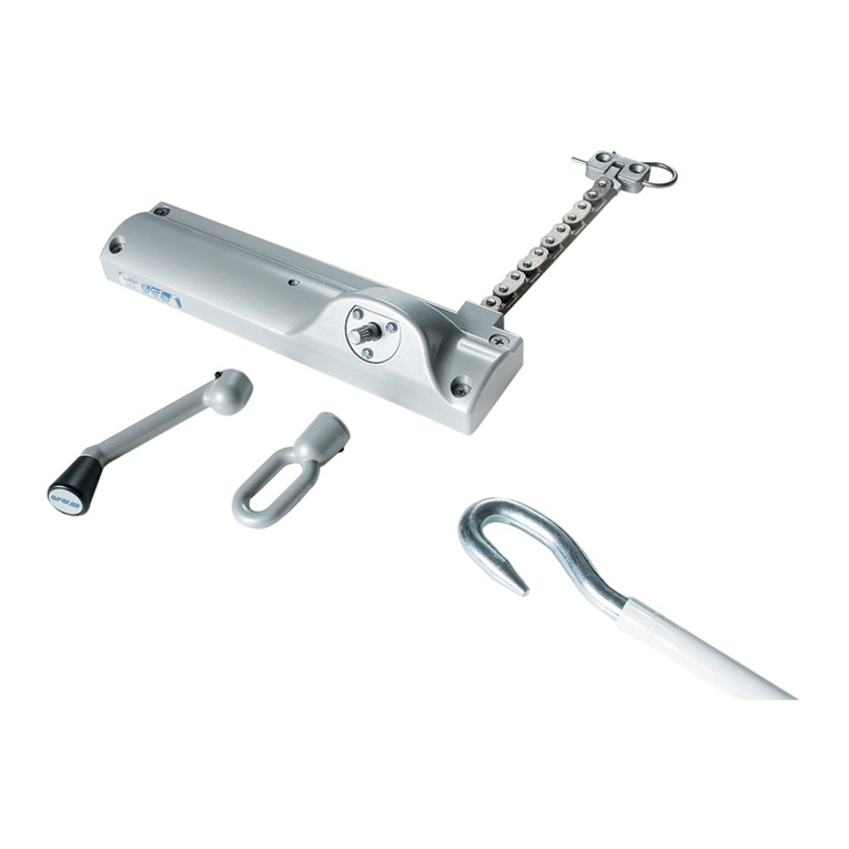
Doc. _____ - Rev. __/__/____
USER MANUAL
EN
Drw. / Dis. .... ____
6/45
MANUALE D’ISTRUZIONI
IT
1.3 Informative letter ....
The installer and the maintenance personnel must
know the content of this manual. Although the
main features of the equipment described in this
manualarenotsubjecttochange,themanufac-
turerreservestherighttomodifythecomponents,
details and accessories it deems necessary to
improve the product or to meet manufacturing or
commercialrequirementsatanymeandwithout
being obliged to update this manual immediately.
WARNING
ALL RIGHTS ARE RESERVED
ACCORDING TO THE
INTERNATIONAL COPYRIGHT
CONVENTIONS,
Thereproduconofanypartofthismanual,
inanyform,isforbiddenwithouttheprior
wrienauthorizaonofthemanufacturer.
Thecontentofthisguidecanbemodied
withoutpriornoce.Greatcarehas
beentakenincollecngandcheckingthe
documentaoncontainedinthismanualto
make it as complete and comprehensible as
possible.
Nothing contained in this manual can be
consideredasawarranty,eitherexpressed
orimplied-including,notinarestricve
way,thesuitabilitywarrantyforanyspecial
purpose.
Nothing contained in this manual can be
interpretedasamodicaonorconrmaon
of the terms of any purchase contract.
The UCS products have not been conceived
to work in areas at risk of explosions. In case
of damage or malfunction, do not use the
actuators and contact the Customer Care
Technical Service.
The original conguraon of the actuator must
not be changed at all, except as prescribed in this
manual. On receiving the actuator, make sure the
supply corresponds to what has been ordered.
In case of non-compliance immediately inform
the manufacturer.
Also make sure the actuator has not been
damaged during transport.
Customer Care Technical Service
Foranyinformaon,pleasecontact
ucs@ultraexgroup.it
WARNING

Doc. _____ - Rev. __/__/____
USER MANUAL
EN
Drw. / Dis. ....____
7/45
MANUALE D’ISTRUZIONI
IT
2. PACKING CONTENTS ....
The actuator is packed in a box with the following
components:
• model NANO DCis supplied with a wired
feeding cable
• models SYNCHRO NANO DC and SYNCHRO
NANO DC F-SIGNAL are equipped with a
8-pole connector to be connected to the
special cable which is sold in a separate kit and
with a side plug.
KIT A KIT C KIT D
TYPE OF KIT
TIPO DI KIT
DESCRIPTION
DESCRIZIONE
COLOUR
COLORE
CODE
CODICE
ASidexedbracketkit
Kit stae sse laterali
GREY/GRIGIO
BLACK/NERO
WHITE/BIANCO
41938T
41939U
41940V
BFront bracket kit
Kit stae frontali
GREY/GRIGIO
BLACK/NERO
WHITE/BIANCO
41935Q
41936R
41937S
CBack bracket kit
Kit stae posteriori
GREY/GRIGIO
BLACK/NERO
WHITE/BIANCO
41932N
41933O
41934P
DBoomhingedwindowbracket
Staa per nestra a vasistas
GREY/GRIGIO
BLACK/NERO
WHITE/BIANCO
41941W
41942X
41943Y
2.1 Accessories not included ....
Accordingtothetypeofinstallaontobecarried
out(seeparagraphs8and9),theactuatormust
bemountedwith thespecicbrackets available
inseparatekits(A-B-C-D)andthepropercables.
2.1.1 Bracket kits/Kit staffe
NANO DC SYNCHRO NANO DC
SYNCHRO NANO DC F-SIGNAL
KIT B

Doc. _____ - Rev. __/__/____
USER MANUAL
EN
Drw. / Dis. .... ____8/45
MANUALE D’ISTRUZIONI
IT
3. UNPACKING ....
Check the actuator. Before installing it, check that
all the items listed are included and that there are
no visible signs of damage.
1. Remove the actuator from the box.
2. Remove all the components from the packaging.
WARNING
DESCRIPTION
DESCRIZIONE
LENGTH
LUNGHEZZA
CODE
CODICE
5P NANO CABLE KIT -WHITE
KIT CAVO NANO 5P-BIANCO 1,5m. 42016T
5P NANO CABLE KIT -BLACK
KIT CAVO NANO 5P-NERO 1,5m. 42017U
8P NANO CABLE KIT -WHITE
F-SIGNAL
KIT CAVO NANO 8P-BIANCO
F-SIGNAL
1,5m. 42020X
DESCRIPTION
DESCRIZIONE
LENGTH
LUNGHEZZA
CODE
CODICE
5P NANO CABLE KIT -WHITE
DOUBLE CONNECTOR
KIT CAVO NANO 5P-BIANCO DOPPIO
CONNETTORE
1 m. 42018V
5P NANO CABLE KIT -BLACK DOUBLE
CONNECTOR
KIT CAVO NANO 5P-NERO DOPPIO
CONNETTORE
1 m. 42019W
To connect models SYNCHRO NANO DC and SYN-
CHRO NANO DC F-SIGNAL,usetheavailablecables
supplied in separate kits. The cable features are shown
inthetablesbelow.Please,refertoparagraph8for
connecons.
NANO ELECTRIC CONNECTOR KIT - 42021Y
KIT CONNETTORE ELETTRICO NANO - 42021Y
4
3
2
REFERENCE
RIFERIMENTO
DESCRIPTION
DESCRIZIONE
1UPPER COVER
CALOTTA SUPERIORE
28 POLE CONNECTOR
CONNETTORE 8 POLI
3LOWER COVER
CALOTTA INFERIORE
4RUBBER CABLE GLAND
GOMMINO PRESSACAVO
2.1.2 Cable kits ....
1

Doc. _____ - Rev. __/__/____
USER MANUAL
EN
Drw. / Dis. ....____9/45
MANUALE D’ISTRUZIONI
IT
4. DATA PLATE ....
The manufacturer’s idencaon and European
Directive conformity plate is located on the
actuator.
Several safety warnings are applied to the actuator;
such warnings must be strictly followed by
everyone dealing with this product.
The company is not to be held responsible for
damage to property or accidents to people which
might occur if the above-menoned warnings are
not observed. In such a case, the operator is the
only person responsible.
TheidencaonplateCE/EACislocatedonthe
right side of the actuator.
Manufacturer’sidencaon
Idencazione costruore
CE/EAC marking
Marcatura CE/EAC
Model/Modello
Electrical features
Caraerische eleriche
Part Number
N° parte Serial Number
N° di serie
ULTRAFLEX CONTROL SYSTEM S.r.l. - Made in Italy
NANO DC
24 Vdc 1A IP40
400 N (spinta-push) 400 N (tiro-pull)
Corsa - Stroke 400 mm
PN: 000000 SN: 0000000000000
IPprotecon
Protezione IP
Mechanical features
Caraerische meccaniche
5 PRODUCT DESCRIPTION ....
The products described in this manual are chain
actuatorsdesignedforapplicaonsonsidehung
andparallelwindows,rooightsandboomhung
windows. The actuator has not been designed for
connuousoperaon.Payaenontotheduty
cyclevalueshowninthemainfeatures(par.6).
• NANO DC is provided with 1.5 m cable without
selectable features (Synchronizaon, feedback
signalandspeedselecon).Thequietoperaon
isensuredbytheslowspeed(4mm/s)fornatural
venlaon.
NANO DC actuators with maximum speed are available
asstandard;quiteoperaonisavailableonrequest.
• Suitable for combined installation with the
addionallockingdeviceE-LOCK.
The actuator is intended for the electromove
opening and closing of windows. It is suitable for
indoor use, only.
Opening takes 60 seconds; the actuator speed is
proporonal to stroke.

Doc. _____ - Rev. __/__/____
USER MANUAL
EN
Drw. / Dis. .... ____10/45
MANUALE D’ISTRUZIONI
IT
• The SYNCHRO NANO versions are equipped with
anintegratedspeedsynchronizaoncontrolboard
fortheinstallaonofmorethanoneactuatoron
the same vent (max 4 actuators), avoiding any
external control panel. The quiet operaon is
acvatedbyUCSC-SVControlPanels;normally,
window opens in 60 seconds at maximum speed.
SYNCHRO NANO versions provide also open/
close feedback. Cable connecon possible on
both sides.
• The SYNCHRO NANO F-SIGNAL versions provide
freepotenalopeningandclosingfeedbacksignal
(maintainedcontact),acvatedbythecurrentlimit.
Thesystemismadeupofthefollowingcomponents:
REFERENCE
RIFERIMENTO
DESCRIPTION
DESCRIZIONE
1ACTUATOR
ATTUATORE
2CHAIN
CATENA
3CONNECTOR
CONNETTORE
4BRACKET(ref.par.2)
STAFFA (vedi par.2)
5CONNECTION CABLE
CAVO DI CONNESSIONE
INSTALLATION EXAMPLE
ESEMPIO DI APPLICAZIONE
4
32
5
1
Cable connecon is possible on both sides on
SYNCHRO NANO and SYNCHRO NANO F-SIGNAL
versions.

Doc. _____ - Rev. __/__/____
USER MANUAL
EN
Drw. / Dis. ....____11/45
MANUALE D’ISTRUZIONI
IT
6 TECHNICAL FEATURES ....
The tables below show the technical features for
NANOmodels:
NANO DC / SYNCHRO NANO DC/
SYNCHRO NANO DC F-SIGNAL
MAIN FEATURES/ CARATTERISTICHE PRINCIPALI
VOLTAGE SUPPLY
ALIMENTAZIONE 24 Vdc ± 15%
CURRENTABSORPTION(withmaxload)
ASSORBIMENTO (a carico max) 1.2 A
OPERATION
COMANDO
polarity inversion
inversione polarità
MAXFORCE(push/pull)
FORZA MAX.(spinta/trazione) 400 N*
SPEED
VELOCITÁ 4-14 mm/s*
DUTY CYCLE
FATTORE DI SERVIZIO 30%
PARALLEL CONNECTION
COLLEGAMENTO IN PARALLELO YES/SI
LIMIT STOP
FINE CORSA
electronic
eleronico
SAFETY STOP
PROTEZIONE
electronic
eleronico
PROTECTION CLASS
GRADO DI PROTEZIONE IP 40
WORKING TEMPERATURE
TEMPERATURA DI ESERCIZIO
from -10 to +60°C
da -10 a +60°C
RELATIVE HUMIDITY
UMIDITÁ RELATIVA 60%
* see the graph
* vedere graco
* see chapter 8.2.6
* vedere cap. 8.2.6
STROKE
CORSA
REAL
REALE
REAL WITHOUT EXTERNAL CHAIN GUIDE
REALE SENZA GUIDA CATENA ESTERNO
200 193 200
300 294 301
400 396 403
500 498 505
600 599 606
800 802 809

Doc. _____ - Rev. __/__/____
USER MANUAL
EN
Drw. / Dis. .... ____12/45
MANUALE D’ISTRUZIONI
IT
STROKE/FORCE - CORSA/FORZA
PULL FORCE - FORZA IN TRAZIONE
PUSH FORCE - FORZA IN SPINTA
Stroke/Corsa (mm)
Force/Forza (N)
MODEL
MODELLO
STROKE (mm)
CORSA (mm)
SPEED SV (mm/s)
VELOCITÁ EFC (mm/s)
SILENT VENTILATION SPEED (mm/s)
VELOCITÁ SILENT VENTILATION (mm/s)
NANO DC
200
300
400
500
600
800
4
5
7
9
10
14
4(nonstandardversion-uponrequestonly)
4 (versione fuori standard - solo su richiesta)
Synchro Nano DC
/ Synchro Nano
DC F-Signal
200
300
400
500
600
800
4
5
7
9
10
14
4

Doc. _____ - Rev. __/__/____
USER MANUAL
EN
Drw. / Dis. ....____13/45
MANUALE D’ISTRUZIONI
IT
Asdescribedinparagraph5,eachNANO model
mayhavedierentfunconalfeatureswhichare
showninthetablebelow:
MODELS
VERSIONI NANO DC SYNCHRO NANO SYNCHRO NANO
F-SIGNAL
ELECTRIC CONNECTION
COLLEGAMENTO ELETTRICO
Silicon cable
Cavo in silicone
1,5m
Fast connector both sides
(1cable-5poles)
Conneore rapido su
entrambi i la (1 cavo - 5
poli)
Fast connector both sides
(1cable-8poles)
Conneore rapido su
entrambi i la (1 cavo - 8
poli)
PARALLEL CONNECTION
COLLEGAMENTO IN
PARALLELO
YES
SI
YES
SI
YES
SI
SYNCHRO CONNECTION
COLLEGAMENTO SYNCHRO NO YES
SI
YES
SI
FEEDBACK NO
YES (with 5-pole cable
feedback in tension
SI (con cavo da 5 poli
feedback in tensione)
YES (with 5-pole cable
feedbackfreepotenal)
SI (con cavo da 5 poli
feedback privo di
potenziale)
SILENT MODE
MODALITÁ SILENZIOSA
Speedproporonal
to opening
stroke. Version for
minimumspeed,
upon request only
Velocità
proporzionale alla
corsa in apertura.
Versione per
velocità sempre
ridoa al minimo,
solo su richiesta.
Speedproporonalto
opening stroke. Pole for
silent version with C-SV*.
Version for minimum
speed,uponrequestonly
Velocità proporzionale alla
corsa in apertura. Polo per
versione silenziosa con
C-SV. Versione per velocità
sempre ridoa al minimo,
solo su richiesta.
Speedproporonalto
opening stroke. Pole for
silent version with C-SV*.
Version for minimum
speed,uponrequestonly
Velocità proporzionale alla
corsa in apertura. Polo per
versione silenziosa con
C-SV. Versione per velocità
sempre ridoa al minimo,
solo su richiesta.
SOFT CLOSE
CHIUSURA LENTA
On BMS version
only
Solo su versione
BMS
On BMS version only
Solo su versione BMS
On BMS version only
Solo su versione BMS
ADDRESSABLE
INDIRIZZABILE
On BMS version
only
Solo su versione
BMS
On BMS version only
Solo su versione BMS
On BMS version only
Solo su versione BMS
ENTRAPMENT RISK
REDUCTION
RIDUZIONE RISCHIO
INTRAPPOLAMENTO
On BMS version
only
Solo su versione
BMS
On BMS version only
Solo su versione BMS
On BMS version only
Solo su versione BMS
PROGRAMMABLE
PARAMETERS
PARAMETRI PROGRAMMABILI
On BMS version
only
Solo su versione
BMS
On BMS version only
Solo su versione BMS
On BMS version only
Solo su versione BMS
* see diagram chapter 8.2.7
* vedere capitolo 8.2.7
6.1 Models 6.1 Versioni

Doc. _____ - Rev. __/__/____
USER MANUAL
EN
Drw. / Dis. .... ____14/45
MANUALE D’ISTRUZIONI
IT
7 DIMENSIONS ....
STROKE (C)
CORSA (C) A L
200
300 254,5 550
400 304,5 600
500
600 404,5 700
800
1000 604,5 900
C
ACTUATOR
ATTUATORE
CONNECTOR
CONNETTORE
SIDE BRACKET KIT
KIT STAFFE FISSE LATERALI
74
48
65
FRONT BRACKET KIT
KIT STAFFE FRONTALI
BRACKET FOR BOTTOM HINGED WINDOWS
STAFFA PER FINESTRA WASITAS
BACK BRACKET KIT
KIT STAFFE POSTERIORI
21
35
15
23
15
16
33
20
52
20
13
4
64
L
A
24
35

Doc. _____ - Rev. __/__/____
USER MANUAL
EN
Drw. / Dis. ....____15/45
MANUALE D’ISTRUZIONI
IT
8 WIRING ....
BEFORE PROCEEDING WITH THE
MECHANICAL MOUNTING OF THE
ACTUATOR ON THE WINDOW, CARRY
OUT THE WIRING OPERATIONS DESCRIBED
BELOW.
Original spare parts and ngs only shall
be used to installa the actuator.
The NANO DC model is provided with 1.5 m cable.
Please,refertothediagrambelowforconnecons.
8.1 NANO DC connection ....
8.1.1 NANO DC wiring diagram ....
*PURCHASABLE “UCS” ACCESSORIES
ACCESSORI “UCS” ACQUISTABILI
*
*
BLUE-BLU
BROWN-MARRONE
A = OPEN-APRE
C = CLOSE-CHIUDE
FEEDER
ALIMENTATORE
PUSHBUTTON(DPOT)
PULSANTE(DPOT)
Before carrying out any wiring
operation, disconnect the power
supply.
WARNING
When the chain actuator is not mounted, pay
great aenon not to retract the chain into the
actuator completely: the chain could get stuck
irreparably.
WARNING
UCS recommends using Dead man push
buons to control the actuators.
Do not connect power supply to the
feedback signal cables.
WARNING

Doc. _____ - Rev. __/__/____
USER MANUAL
EN
Drw. / Dis. .... ____16/45
MANUALE D’ISTRUZIONI
IT
8.2.1 SYNCHRO NANO wiring
diagram (single actuator
connection)
....
8.2.2 SYNCHRO NANO F-SIGNAL
wiring diagram (single actuator
connection)
....
*
*
A = OPEN-APRE
C = CLOSE-CHIUDE
COM = COMMON-COMUNE
PUSHBUTTON(DPOT)
PULSANTE(DPOT)
FEEDER
ALIMENTATORE
EXAMPLE-ESEMPIO
*PURCHASABLE “UCS” ACCESSORIES/ACCESSORI “UCS” ACQUISTABILI
BLUE-BLU
BROWN-MARRONE
GREY-GRIGIO
BLACK-NERO
WHITE-BIANCO
SIGNAL
SEGNALAZIONE
The SYNCHRO NANO and SYNCHRO NANO
F-SIGNAL models are provided with two
connectors at the actuator ends. Both the main
and the addional one will need to be used if
severalactuators(max.4)areconnected.
8.2 SYNCHRO NANO - SYNCHRO NANO
F-SIGNAL connection
....
*
*PURCHASABLE “UCS” ACCESSORIES/ACCESSORI “UCS” ACQUISTABILI
BLUE-BLU
BROWN-MARRONE
GREY-GRIGIO
BLACK-NERO
WHITE-BIANCO
PUSHBUTTON(DPOT)
PULSANTE(DPOT)
FEEDER
ALIMENTATORE
SIGNAL
SEGNALAZIONE
A = OPEN-APRE
C = CLOSE-CHIUDE
COM = COMMON-COMUNE
EXAMPLE-ESEMPIO

Doc. _____ - Rev. __/__/____
USER MANUAL
EN
Drw. / Dis. ....____17/45
MANUALE D’ISTRUZIONI
IT
8.2.3 Connection example (SYNCHRO
NANO DC - SYNCHRO NANO
DC F-SIGNAL)
....
EXAMPLE OF CONNECTION OF SEVERAL
SYNCHRONIZED ACTUATORS USING CABLES
SUPPLIED BY UCS
*
42018V white double connector cable
42019W black double connector cable
42018V cavo doppio conneore bianco
42019W cavo doppio conneore nero
CONNECT BLUE, BROWN, WHITE,
BLACK AND GREY CABLES
ACCORDING TO THE ELECTRIC
DIAGRAMS 8.2.1 AND 8.2.2
COLLEGARE I FILI BLU, MARRONE,
BIANCO, NERO E GRIGIO SECONDO
GLI SCHEMI ELETTRICI 8.2.1 E 8.2.2
42016T white cable kit
42017U black cable kit
42016T kit cavo bianco
42017U kit cavo nero
**
** **
**
LENGTH = 1m
LUNGHEZZA = 1m LENGTH=1,5m
LUNGHEZZA = 1,5m
42021Y NANO electric connector kit
42021Y kit conneore elerico NANO

Doc. _____ - Rev. __/__/____
USER MANUAL
EN
Drw. / Dis. .... ____18/45
MANUALE D’ISTRUZIONI
IT
8.2.4 Voltage drop for actuator
chain
....
This paragraph shows examples of drop voltage in
case of actuators connected in chain.
The diagram shows the typical voltage drop of
actuators with stroke of 1000 mm operang
at maximum load and cables supplied by UCS.
The allowed voltage (24 Vdc +/- 15%) must
be checked on the rst and last actuator of
the chain. If necessary, adjust the feeder
voltage so that the maximum limit (27.6 V)
for the rst actuator of the chain while the
actuators are operang and the minimum
one (20.4) for the last actuator of the chain
are not exceeded.
WARNING
Ifthedatausedforcalculaonschange,acheck
by UCS is needed.
42016T white cable kit
42017U black cable kit
42016T kit cavo bianco
42017U kit cavo nero
*
**
42018V white double connector cable
42019W black double connector cable
42018V cavo doppio conneore bianco
42019W cavo doppio conneore nero
ΔV = 2.5V
ΔV = 5V
LENGTH = 1m
LUNGHEZZA = 1m
LENGTH=1,5m
LUNGHEZZA = 1,5m
42021Y NANO electric connector kit
42021Y kit conneore elerico NANO

Doc. _____ - Rev. __/__/____
USER MANUAL
EN
Drw. / Dis. ....____19/45
MANUALE D’ISTRUZIONI
IT
Insert the connector “1” into the proper space on
the actuator and make sure it is locked.
To carry out the main connection, use a
5-polecable“2”;fortheconneconbetween
twoactuators,usea5-polecable“3”(see
thepicturebelow).
WARNING
In order to remove the connector, DO NOT PULL
THE CABLE; release the special wings by using two
screwdrivers.
Insert the supplied rubber plug “4” into the
actuator end which is not used.
8.2.5 Cable connection ....
PUSH
2
3
4
1

Doc. _____ - Rev. __/__/____
USER MANUAL
EN
Drw. / Dis. .... ____20/45
MANUALE D’ISTRUZIONI
IT
8.2.6 Customized cable wiring ....
The 8-pin connector allows the enabling of the
actuatorfuncons.
POWER SUPPLY (PIN 1 - PIN 2)
PIN 1 +24V and PIN 2 -24V are pins supplying power to
Synchro NANO and Synchro NANO F-SIGNAL cards.
Byinverngpolaritythroughabuon,itispossible
toinvertthedireconoftheactuators:
PIN 1 +24 V
PIN 2 -24 V
PIN 1 -24 V
PIN 2 +24 V
Z
Z Opening
t
Z
Z tClosing
SV MODE (PIN 3 SV)
TheSVfuncon(SmokeandHeatExhaustVenlaon)
allows the actuator to open windows by 60 seconds
(incompliancewiththeregulaoninforce)according
tothechainstroke.TheSV(silentvenlaon)input
of actuators SYNCHRO NANO and SYNCHRO NANO
F-SIGNAL must be given a voltage of 24V +/-10%.
Beingasignalline,absoronislesssignicantthan
that of the actuator power supply. The input works
asfollows:
• If the input is NOT powered or it is disconnected
(even if the line is accidentally interrumpted),
the actuator works at standard speed to ensure
a complete opening within 1 minute (see table
inchapter6)sothattheactuatorcanbeusedfor
smoke exhaust according to standard EN12101-2.
•Iftheinputispoweredat24V,theactuatorworks
in“silentvenlaon”(SV)mode,alwaysworking
attheminimumspeed(4mm/s).
TheC-SVunitsmadebyUCScanmanagetheautomac
commutation between the two modes mentioned
above:justconnecttheactuatorSVinputtoterminal“+”
of output 24V_AUX.
Upon previous request by the customer, UCS can
permanentlyenabletheSVfunconduringproducon.
Insuchacase,theactuatoralwaysopensandclosesat
minimumspeed,regardlessoftheSVinputcondion.
CONNECTION
BETWEEN TWO
ACTUATORS
COLLEGAMENTO TRA
DUE ATTUATORI
C= CHIUDE - CLOSE - FERME
ZU - CIERRE
ACCESSORI "UCS" ACQUISTABILI
PURCHASABLE "UCS" ACCESSORIES
ACCESSOIRES "UCS" ACHETABLES
ZUBEHÖRTEILE "UCS"
ACCESORIOS "UCS" COMPRABLES
A= APRE - OPEN - OUVRE
AUF - APERTURA
PULSANTE (DPDT)
PUSH BUTTON (DPDT)
BOUTON POUSSUAR (DPDT)
DRUCKNOPF (DPDT)
PULSADOR (DPDT)
M
L
I
H
EH
F
D
PIN FUNCTION
FUNZIONE
1 +/-24V
2+/-24V
3 SV/EFC
4 CAN H - SYNCHRO
5 CAN L - SYNCHRO
6Opening signal
Segnale di apertura
7Closing signal
Segnale di chiusura
8COM
24 6 8
135 7
MODALITÁ EFC (PIN 3 EFC)
....
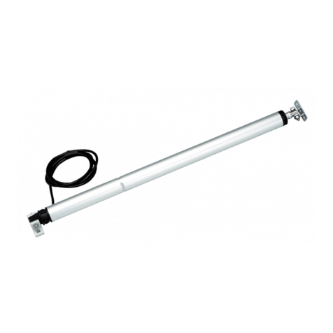
Other manuals for NANO DC
1
This manual suits for next models
2
Table of contents
Other UCS Controllers manuals