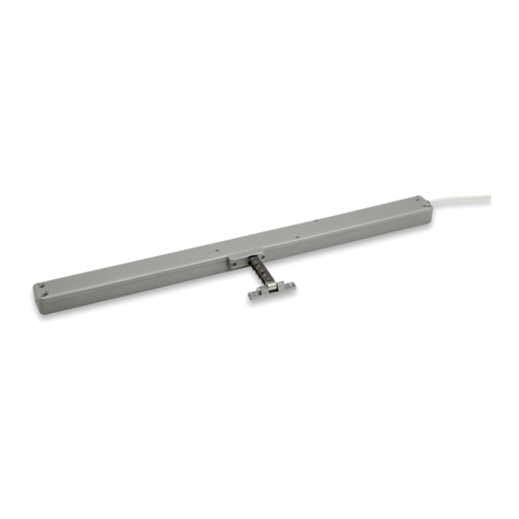
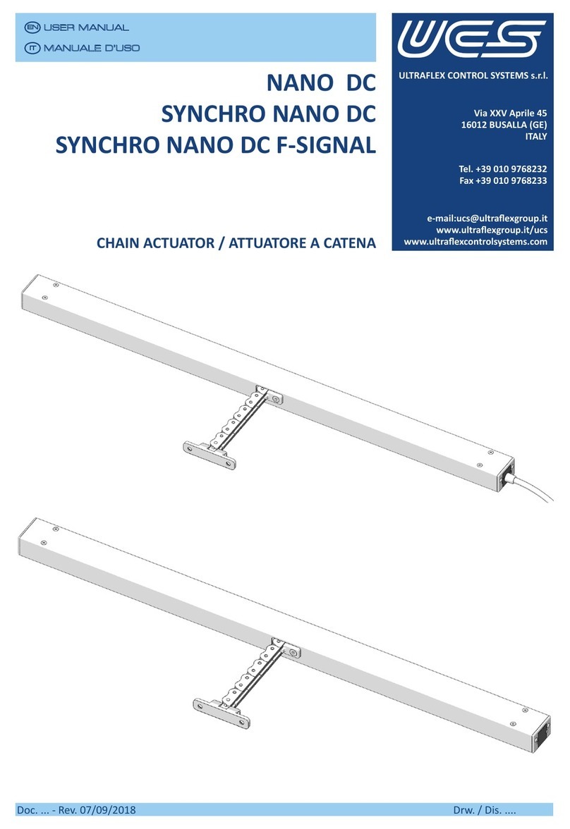
UCS NANO DC User manual

NANONANO
Doc. 85858G - Rev. 08/04/2020 Drw. / Dis. 33701/b
1/43
ULTRAFLEX CONTROL SYSTEMS s.r.l.
Via XXV Aprile 45
16012 BUSALLA (GE)
ITALY
Tel. +39 010 9768232
Fax +39 010 9768233
Doc. 85858G - Rev. 08/04/2020 Drw. / Dis. 33701/b
NANO DC
SYNCHRO NANO DC
SYNCHRO NANO DC F-SIGNAL
MANUALE D’USO
MANUALE D’USO
USER MANUAL
USER MANUAL
IT
IT
EN
EN

Doc. 85858G - Rev. 08/04/2020
USER MANUALUSER MANUAL
ENEN
Drw. / Dis. 33701/b
2/43
MANUALE D’ISTRUZIONIMANUALE D’ISTRUZIONI
ITIT

NANONANO
Doc. 85858G - Rev. 08/04/2020 Drw. / Dis. 33701/b3/43
CONTENTS INDICE
1. INTRODUCTION............................................4
1.1 Symbols used .........................................4
1.2 General safety rules ...............................4
1.3Informaveleer...................................7
2. PACKING CONTENTS.....................................8
2.1 Accessories not included .......................8
2.1.1 Bracket kits.....................................8
2.1.2 Cable kits........................................9
3. UNPACKING..................................................9
4. DATA PLATE ................................................10
5. PRODUCT DESCRIPTION.............................10
6. TECHNICAL FEATURES ................................12
6.1 Models .................................................14
7. DIMENSIONS..............................................15
8. WIRING ......................................................16
8.1NANODCconnecon...........................16
8.1.1 NANO DC wiring diagram.............16
8.2 SYNCHRO NANO - SYNCHRO NANO
F-SIGNALconnecon ...........................17
8.2.1 SYNCHRO NANO wiring diagram
(singleactuatorconnecon)......17
8.2.2 SYNCHRO NANO F-SIGNAL wiring
diagram (single actuator
connecon) ................................18
8.2.3 Connection example (SYNCHRO
NANO DC-SYNCHRO NANO DC
F-SIGNAL ....................................18
8.2.4 Voltage drop for actuator chain .19
8.2.5 Cableconnecon .......................20
8.2.6 Customized cable wiring ............21
8.2.7 Specialapplicaons....................24
9. INSTALLATION ............................................25
9.1 Necessary tools ...................................25
9.2 Top hung window open outwards - side
bracket with sill...................................26
9.3 Top hung window open outwards -
concealedinstallaon .........................28
9.4 Top hung window open outwards -
concealed wing with front bracket .....30
9.5 Top hung window open outwards - with
front bracket .......................................32
9.6Boomhung windowopen inwards(Z
bracket+pivongbracket) .................34
9.7 Bottom hung window open inwards -
actuator on wing.................................37
9.8Boomhung windowopen outwards-
concealedinstallaon .........................40
10. MAINTENANCE ..........................................42
11. CLEANING ..................................................42
12. DISPOSAL ...................................................43
13. WARRANTY ................................................43
1. INTRODUZIONE............................................4
1.1 Simbologia impiegata.............................4
1.2 Norme generali di sicurezza...................4
1.3Leerainformava.................................7
2. CONTENUTO DELL’IMBALLO ........................8
2.1 Accessori non inclusi..............................8
2.1.1Kitstae .........................................8
2.1.2 Kit cavi............................................9
3. DISIMBALLAGGIO.........................................9
4. DATI DI TARGA............................................10
5. DESCRIZIONEDELPRODOTTO....................10
6. CARATTERISTICHE TECNICHE .....................12
6.1 Versioni ................................................14
7. DIMENSIONI...............................................15
8. COLLEGAMENTI ELETTRICI.........................16
8.1 Collegamento NANO DC.......................16
8.1.1SchemaelericoNANODC ..........16
8.2 Collegamento SYNCHRO NANO - SYNCHRO
NANO F-SIGNAL ...................................17
8.2.1 Schema elettrico SYNCHRO NANO
(collegamentoauatoresingolo) .17
8.2.2 SchemaelericoSYNCHRONANO
F-SIGNAL(collegamento auatore
singolo).......................................18
8.2.3 Esempio di collegamento (SYNCHRO
NANO DC-SYNCHRO NANO DC
F-SIGNAL ....................................18
8.2.4 Cadutetensionecatenaauatori ...19
8.2.5 Collegamento cavi......................20
8.2.6 Collegamento cavo personalizzato.21
8.2.7 Applicazioni speciali ...................24
9. INSTALLAZIONE ..........................................25
9.1 Utensili necessari ................................25
9.2 Finestraasporgereversol’esterno-staa
laterale su davanzale...........................26
9.3 Finestra a sporgere verso l’esterno -
installazione nascosta .........................28
9.4 Finestra a sporgere verso l’esterno - anta
nascostaconstaafrontale ................30
9.5 Finestra a sporgere verso l’esterno - con
staafrontale......................................32
9.6 Finestra vasistas ad apertura verso l’interno
(staaa“Z”+staaoscillante).............34
9.7 Finestra vasistas ad apertura verso l’interno
-auatoresuanta ..............................37
9.8 Finestra vasistas ad apertura verso l’esterno
- installazione nascosta .......................40
10. MANUTENZIONE.......................................42
11. PULIZIA.......................................................42
12. SMALTIMENTO...........................................43
13. GARANZIA ..................................................43
Doc. 85858G - Rev. 08/04/2020
USER MANUALUSER MANUAL
ENEN
Drw. / Dis. 33701/b
4/43
MANUALE D’ISTRUZIONIMANUALE D’ISTRUZIONI
ITIT
1.2 General safety rules
This manual is an integral part of NANO
actuators and it must be carefully read
beforeusesinceitgivesimportantindicaons
withregardstoitssafeinstallaon,useand
maintenance. Keep it with care.
BeforeusingNANOactuators,readcarefully
the following general safety rules.
Thisactuatorisonlytobeedonwindows
that are out of reach of people.
Be very careful of moving parts during
installaontoavoidcrushing.
Boomhingedwindowsmustbeprovided
with side checks.
Priortoinstallaonmakesurethat:
• the actuator performances comply
withtheesmatedapplicaon
• window profiles and fittings are
suitable to the stresses caused by the
actuator
• windowngs(hinges)andabsence
of obstacles allow complete opening
• theexisngelectricsystemscomply
withtheregulaonsinforce
• power supply features are those
indicatedintheactuatorspecicaons
• the declared nominal values do
notconsideranywind stress:it is
necessary to evaluate it correctly to
avoid any failure of the actuator or
ofthewindow,parcularlyincaseof
large windows.
Unsuitableapplicaonorwronginstallaon
may result in a loss of system operating
funconsandconsequentlyindamagesor/
and injuries.
1 INTRODUCTION ....
The operations which can be dangerous
if they are not carried out correctly are
indicated with this symbol.
Danger to persons due to electricity.
Theoperaonswhoseexecuonrequires
qualiedor specializedstatoavoidany
danger are indicated with this symbol.
Important information for a correct
installaonanduseoftheproduct.
Danger of hands crushing
1.1 Symbols used ....
1 INTRODUZIONE
1.1 Simbologia impegata
Leoperazionichepossonopresentarerischi,
senon effettuate correttamente, sono
indicateconilsimboloindicatoquiaanco.
Pericolodinaturaelericachepuòcausare
danno alle persone.
Le operazioni per la cui esecuzione si richiede
personalequalicatoo specializzato, onde
evitarepossibilirischi,sonoevidenziatecon
ilsimboloindicatoquiaanco.
Informazione ritenuta importante per una
correainstallazioneeulizzodelprodoo.
Pericolo di schiacciamento mani
1.2 Norme generali di sicurezza
Il presente manuale d’uso è parte integrante
degli attuatori NANO e deve essere letto
attentamente prima dell’utilizzo poiché
fornisceimportanindicazioniriguardanla
sicurezzadiinstallazione,usoemanutenzione.
Conservare con cura.
Primadiusaregli auatoriNANO,leggere
aentamentelenormegeneralidisicurezza
seguen.
Questoauatoredeveesseremontatosolosu
nestrealdifuoridellaportatadellepersone.
Porre molta attenzione alle parti in
movimentodurantel’installazione:pericolo
di schiacciamento. I serramenti a vasistas
devonoessereprovvisdicompassidiarresto.
Primadiprocedereall’installazionevericare
che:
• le prestazioni dell’attuatore siano
adeguate all’applicazione prevista
• iproliegliaccessoridelserramento
sianoadeguatamentedimensionaper
lesollecitazioniprodoedell’auatore
• gliaccessoridelserramento(cerniere)
el’assenzadiimpedimenconsentano
la completa corsa di apertura
• gli impianti elettrici esistenti siano
conformiallenormevigen
• l’alimentazione elettrica abbia le
caraerischeindicateneidatecnici
dell’auatore
• I valori nominali non tengano conto
dellesollecitazionicausatedalvento:
ènecessarioconsiderareaentamente
questo aspetto per evitare
malfunzionamenti dell’attuatore o
dellanestra,soprauosedigrandi
dimensioni.
Un’applicazione impropria o un’installazione
scorreaposso pregiudicarela funzionalità
delsistemaequindi provocaredanni a
persone e/o cose.

NANONANO
Doc. 85858G - Rev. 08/04/2020 Drw. / Dis. 33701/b
5/43
Whenoperatingtheactuator,followthe
instruconsbelow:
• preventliquids fromenteringthe
actuator
• donot approachmovingparts unl
they have come to a complete stop
• at least once a year check at sight for
damages or wear in the supply cable
• do not carry out any intervention
onthe actuator, donot removeor
disassemble parts of the actuator;
in case of malfunction or damaged
cablecontact“UCS-UltraexControl
Systemssrl”
Beforeconnecng theactuatorto power
supplymakesureithasbeenturnedoto
avoidelectrocuon.
An omnipolar switch shall be provided in the
supplymains(accordingtoCEIEN60335-1).
In case the actuator is installed on a mobile
wing,makesurethesupply cableisnot
subjecttostresswhenoperang.
In case the window is accessible at a height
of2,5matleastprovidethesystemwithan
emergencyswitcho.Itisalsoadvisableto
installamaintainedcontactpush-buon.
Pay aenon when closing the window:
danger of crushing.
Incaseofinstallaonwithautomacsystems,
please contact UCS Technical Support. If the
automatic system enables the actuators
connuously,the mechanicand electronic
components could wear prematurely.
Prima di eseguire il collegamento elettrico
dell’attuatore, assicurarsi di aver tolto
l’alimentazione dalla linea per evitare folgorazioni.
Prevederenellaretedialimentazioneundisposivo
onnipolare di sconnessione (secondo CEI EN
60335-1).
Nelcasodiinstallazionedell’auatoresuanta
mobile,vericarecheilcavodialimentazione
non sia sollecitato durante il funzionamento.
Nel caso in cui il serramento sia accessibile ad
un’altezzaminoredi2,5mtdotareilsistema
dicomandodiunarrestodiemergenzae,
possibilmente,di unpulsantea contatto
mantenuto.
Durante l’uso dell’attuatore osservare le
seguenavvertenze:
• evitare penetrazione di liquidi
nell’auatore
• nonavvicinarsialleparinmovimento
noalcompletoarrestodellestesse
• controllare visivamente almeno
una volta all’anno che il cavo di
alimentazione non sia danneggiato e
nonsianopresenaltrisegnidiusura
• noneeuareintervensull’auatore,
non aprire o smontare parti
dell’auatore;in casodi anomalieo
cavodanneggiatorivolgersia“UCS–
UltraexControlSystemssrl”
Incasodiinstallazioneconsistemiautomaci,
rivolgersi all’Assistenza Tecnica UCS. Nel caso
incuiilsistemaautomacoavigliauatori
inmanieraconnua,sipotrebbeavereuna
degenerazione precoce della meccanica e
dell’eleronicadeglistessi.
Prestareaenzionedurantelachiusuradella
nestra:pericolodischiacciamento.
If opening or closing controls are enabled
repeatedly and/orfrequently, theactuator
could be damaged and its service life could
be reduced.
I comandi di apertura o chiusura ripetuti e/o
ravvicinati possono danneggiare l’attuatore o
ridurnelavitaule.
Opening and closing controls cannot be
enabledatthesameme. Lacontemporaneitàdei comandidi aperturae
chiusura non è ammessa.
Installman-presencecontrols,only. In the
automacsystems,makesure thecontrol
isenabledonlyforthemethatisneeded
for the complete opening or closing of the
actuator.
Installare esclusivamente comandi a presenza
d’uomo.Nei sistemiautomaciassicurarsiche
il comando venga mantenuto solo per il tempo
necessario ad una completa apertura o chiusura
dell’auatore
Any installaon and/or maintenance tasks
areonlytobecarriedoutbyskilled,specialist
personnel. Exisng electrical systems must
comply with the rules in force in the country
where the actuator is installed. Before doing
anymaintenance,makesurethatthepower
supply has been disconnected. Conform to
the wiring diagrams shown in this manual.
Qualsiasi intervento di installazione e/o
manutenzione deve essere eeuato da
personale competente e specializzato. Gli
impian elerici esisten devono essere
conformi alle norme vigen nel Paese in cui
avviene l’installazione. Prima di eseguire
qualsiasiinterventodimanutenzione,assicurarsi
chela retesia scollegata. Rispearegli schemi
elericiriportanelpresentemanuale.

Doc. 85858G - Rev. 08/04/2020
USER MANUALUSER MANUAL
ENEN
Drw. / Dis. 33701/b
6/43
MANUALE D’ISTRUZIONIMANUALE D’ISTRUZIONI
ITIT
Cables must be laid properly, so that they
cannotbecut,bentortwisted.Itisnecessary
to provide the cables laid into the window
proleswithinsulangtubesabletoresistto
extreme temperatures.
Cables must always be routed by skilled
technicians according to the manufacturer’s
specicaons.
The installaon of two actuators on the
same window is possible only using Synchro
version actuators.
The power control and the actuators included
in this catalogue are not to be considered
“machinery” pointed out in the direcve
2006/42/CE and following modicaon. In
case they are included in systems that are part
oftheapplicaoneldofthesedirecves,itis
responsibilityof theinstallerthe fullmentof
thesafetyrequisites.
Icavidevonoessereposacorreamente,in
mododanontagliarsi,piegarsioaorcigliarsi.
E’ necessario inoltre dotare i cavi posa nei
prolidelserramentoditubiisolaningrado
di resistere a temperature estreme.
I cavi devono sempre essere posa da
tecnici qualica secondo le speciche del
costruore.
L’installazione di due auatori sullo stesso
serramento è possibile solo ulizzando gli
auatoriversioneSynchro.
Isistemidicomandoegliauatoridescri
nel presente manuale non devono essere
considera “macchine” denite dalla
direva2006/42/CEesuccessivemodiche.
Nelcasoincuisianointegrainsistemiilcui
campodiapplicazionesiadipernenzaditali
direve, è responsabilità dell’installatore
soddisfareirequisidisicurezza.
Thecabletypes,lenghts andseconsmust
be choosen according to the technical
specicaonsprovidedbythemanufacturer.
Lepologie,lelunghezzeelesezionideicavi
devonoesserescelteinbaseallespeciche
funzionalifornitedalcostruore.

NANONANO
Doc. 85858G - Rev. 08/04/2020 Drw. / Dis. 33701/b
7/43
1.3 Informative letter 1.3 Lettera informativa
The installer and the maintenance personnel must
know the content of this manual. Although the
mainfeaturesoftheequipmentdescribedinthis
manualarenotsubjecttochange,themanufac-
turerreservestherighttomodifythecomponents,
details and accessories it deems necessary to
improve the product or to meet manufacturing or
commercialrequirementsatanymeandwithout
being obliged to update this manual immediately.
WARNING
WARNING
ALL RIGHTS ARE RESERVED
ACCORDING TO THE
INTERNATIONAL COPYRIGHT
CONVENTIONS,
Thereproduconofanypartofthismanual,
inanyform,isforbiddenwithouttheprior
wrienauthorizaonofthemanufacturer.
Thecontentofthisguidecanbemodied
withoutpriornoce.Greatcarehas
beentakenincollecngandcheckingthe
documentaoncontainedinthismanualto
make it as complete and comprehensible as
possible.
Nothing contained in this manual can be
consideredasawarranty,eitherexpressed
orimplied-including,notinarestricve
way,thesuitabilitywarrantyforanyspecial
purpose.
Nothing contained in this manual can be
interpretedasamodicaonorconrmaon
of the terms of any purchase contract.
The UCS products have not been conceived
to work in areas at risk of explosions. In case
ofdamageor malfunction,do notuse the
actuators and contact the Customer Care
Technical Service.
Foranyinformaon,pleasecontact
ucs@ultraexgroup.it
WARNING
WARNING
L’installatore el’addeoalla manutenzionehanno
l’obbligo di conoscere il contenuto del presente man-
uale.Fermerestandolecaraerischeessenzialidel
podiarezzatura,ilproduoresiriservaildiriodi
apportareleeventualimodicheapar,deagliedac-
cessori,cheriterràopportuneperilmiglioramentodel
prodoooperesigenzedicaraerecostruvoocom-
merciale,inqualunquemomentoesenzaimpegnarsi
adaggiornaretempesvamentequestapubblicazione.
ATTENZIONE
ATTENZIONE
TUTTI I DIRITTI SONO RISERVATI
AI SENSI DELLA
INTERNATIONAL COPYRIGHT
CONVENTIONS,
Évietatalariproduzionediqualsiasipartedi
questomanuale,inqualsiasiforma,senza
l’esplicitopermessoscriodelproduore.
Ilcontenutodiquestaguidapuòessere
modicatosenzapreavviso.Ognicuraè
statapostanellaraccoltaenellavericadella
documentazionecontenutainquestomanuale
perrenderelaguidaquantopiùcompletae
comprensibile.
Nulladiquantocontenutonellapresente
pubblicazionepuòessereinterpretatocome
garanzia o condizione espressa o implicita - inclusa
noninvialimitavalagaranziadiidoneitàper
unparcolarescopo.Nulladiquantocontenuto
nellapresentepubblicazionepuòinoltreessere
interpretatocomemodicaoasserzionedei
terminidiqualsivogliacontraodiacquisto.
IprodoUCSnonsonoprogeaperfunzionare
inambienconpericolodiesplosioni.Incasodi
guasononcorreofunzionamento,gliauatori
nondevonoessereutilizzatifino aquando il
Servizio Assistenza Tecnicanon abbiaulmato
l’intervento di riparazione.
Per informazioni rivolgersi a
ucs@ultraexgroup.it
ATTENZIONE
ATTENZIONE

Doc. 85858G - Rev. 08/04/2020
USER MANUALUSER MANUAL
ENEN
Drw. / Dis. 33701/b
8/43
MANUALE D’ISTRUZIONIMANUALE D’ISTRUZIONI
ITIT
2. PACKING CONTENTS 2. CONTENUTO DELL’IMBALLO
The actuator is packed in a box with the following
components:
• model NANO DCis supplied with a wired
feeding cable
• models SYNCHRO NANO DC and SYNCHRO
NANO DC F-SIGNALareequipped with a
8-pole connector to be connected to the
special cable which is sold in a separate kit and
with a side plug.
KIT A KIT C KIT D
TYPE OF KIT
TIPO DI KIT
DESCRIPTION
DESCRIZIONE
COLOUR
COLORE
CODE
CODICE
ASidexedbracketkit
Kit stae sse laterali
GREY/GRIGIO
BLACK/NERO
WHITE/BIANCO
41938T
41939U
41940V
BFront bracket kit
Kit stae frontali
GREY/GRIGIO
BLACK/NERO
WHITE/BIANCO
41935Q
41936R
41937S
CBack bracket kit
Kit stae posteriori
GREY/GRIGIO
BLACK/NERO
WHITE/BIANCO
41932N
41933O
41934P
DBoomhingedwindowbracket
Staa per nestra a vasistas
GREY/GRIGIO
BLACK/NERO
WHITE/BIANCO
41941W
41942X
41943Y
2.1 Accessories not included 2.1 Accessori non inclusi
Accordingtothetypeofinstallaontobecarried
out(seeparagraphs8and9),theactuatormust
bemountedwiththe specicbracketsavailable
inseparatekits(A-B-C-D)andthepropercables.
2.1.1 Bracket kits/Kit staffe
NANO DC SYNCHRO NANO DC
SYNCHRO NANO DC F-SIGNAL
KIT B
L’auatoreviene imballatoinuna scatolaconi
componenindicadiseguito:
• il modello NANO DCè fornito con un cavo di
alimentazionegiàcollegato
• i modelli SYNCHRO NANO DC e SYNCHRO
NANO DC F-SIGNAL sono dotati di un
conneore a8 polida collegare all’apposito
cavo venduto in un kit separato e di un tappo
laterale.
Asecondadelpodiinstallazioneda eeuare
(vediparagrafi 8e 9),l’attuatoredeveessere
montatoconlespecichestaedisponibiliinkit
separa(A-B-C-D)econgliapposicavi.

NANONANO
Doc. 85858G - Rev. 08/04/2020 Drw. / Dis. 33701/b9/43
3. UNPACKING 3. DISIMBALLAGGIO
1. Remove the actuator from the box.
2. Remove all the components from the packaging.
WARNING
WARNING
DESCRIPTION
DESCRIZIONE
FUNCTION
FUNZIONE
LENGTH
LUNGHEZZA
CODE
CODICE
5P NANO CABLE KIT -WHITE
KIT CAVO NANO 5P-BIANCO
POWER SUPPLY/SIGNAL
ALIMENTAZIONE/SEGNALAZIONE 1,5m. 42016T
5P NANO CABLE KIT -BLACK
KIT CAVO NANO 5P-NERO
POWER SUPPLY/SIGNAL
ALIMENTAZIONE/SEGNALAZIONE 1,5m. 42017U
DESCRIPTION
DESCRIZIONE
FUNCTION
FUNZIONE
LENGTH
LUNGHEZZA
CODE
CODICE
5P NANO CABLE KIT -WHITE DOUBLE CONNECTOR
KIT CAVO NANO 5P-BIANCO DOPPIO CONNETTORE
POWER SUPPLY/SYNCHRO
ALIMENTAZIONE/SINCRO 1 m. 42018V
5P NANO CABLE KIT -BLACK DOUBLE CONNECTOR
KIT CAVO NANO 5P-NERO DOPPIO CONNETTORE
POWER SUPPLY/SYNCHRO
ALIMENTAZIONE/SINCRO 1 m. 42019W
To connect models SYNCHRO NANO DC and SYN-
CHRO NANO DC F-SIGNAL,usetheavailablecables
supplied in separate kits. The cable features are shown
inthetablesbelow.Please,refertoparagraph8for
connecons.
NANO ELECTRIC CONNECTOR KIT
KIT CONNETTORE ELETTRICO NANO
CODE
CODICE
1UPPER COVER
CALOTTA SUPERIORE
42021Y
28 POLE CONNECTOR
CONNETTORE 8 POLI
3LOWER COVER
CALOTTA INFERIORE
4RUBBER CABLE GLAND
GOMMINO PRESSACAVO
2.1.2 Cable kits 2.1.2 Kit cavi
Per il collegamento dei modelli SYNCHRO NANO
DC e SYNCHRO NANO DC F-SIGNAL,ulizzareicavi
disponibiliforniinkit separa.Le caraerische
dei cavi sono riportate nelle tabelle sotto. Per i
collegamen,fareriferimentoalparagrafo8.
1. Estrarrel’auatoredallascatola.
2. Estrarretucomponendallaconfezione.
ATTENZIONE
ATTENZIONE
4
3
2
1

Doc. 85858G - Rev. 08/04/2020
USER MANUALUSER MANUAL
ENEN
Drw. / Dis. 33701/b
10/43
MANUALE D’ISTRUZIONIMANUALE D’ISTRUZIONI
ITIT
4. DATA PLATE 4. DATI DI TARGA
Themanufacturer’s idencaonandEuropean
Directive conformity plate is located on the
actuator.
Several safety warnings are applied to the actuator;
such warnings must be strictly followed by
everyone dealing with this product.
TheidencaonplateCE/EACislocatedonthe
right side of the actuator.
Manufacturer’sidencaon
Idencazione costruore
CE/EAC marking
Marcatura CE/EAC
Model/Modello
Electrical features
Caraerische eleriche
Part Number
N° parte Serial Number
N° di serie
ULTRAFLEX CONTROL SYSTEM S.r.l. - Made in Italy
NANO DC
24 Vdc 1A IP40
400 N (spinta-push) 400 N (tiro-pull)
Corsa - Stroke 400 mm
PN: 000000 SN: 0000000000000
IPprotecon
Protezione IP
Mechanical features
Caraerische meccaniche
5 PRODUCT DESCRIPTION 5 DESCRIZIONE DEL PRODOTTO
The products described in this manual are chain
actuatorsdesignedforapplicaonsonsidehung
andparallelwindows,rooightsandboomhung
windows. The actuator has not been designed for
connuousoperaon.Payaenontotheduty
cyclevalueshowninthemainfeatures(par.6).
• NANO DC is provided with 1.5 m cable without
selectablefeatures (Synchronization,feedback
signalandspeedselecon).Thequietoperaon
isensuredbytheslowspeed(4mm/s)fornatural
venlaon.
NANO DC actuators with maximum speed are
availableasstandard;quiteoperaonisavailable
onrequest.
• Suitable for combined installation with the
addionallockingdeviceE-LOCK.
Sull’auatoresonoriportaidadiidencazione
delcostruttoree diconformitàalle Direttive
Europee.
Inoltre,sonoriportatealcuneavvertenzedisicurezza
che devono essere attentamente rispettate da
chiunquesiappresadusareilprodoo.
LatargadiidencazioneCE/EACèapplicatasul
latodestrodell’auatore.
Iprododescrinelpresentemanualesonoauatori
a catena progettati per applicazioni su finestre a
sporgere eparallele,finestreda tetto evasistas.
L’attuatore non è progettato per il funzionamento
continuo. Prestare attenzione al fattore di servizio
riportatonellecaraerischeprincipali(par.6).
• Il NANO DCèprovvistodicavoda1,5medèprivo
dicaraerischeselezionabili(sincronizzazione,
segnaledi feedback eselezione velocità).Il
funzionamentosilenziosoègarantodallalimitata
velocità(4mm/s)incasodivenlazionenaturale.
Gliauatori NANO DCamassimavelocitàsono
disponibili come standard; arichiesta,èdisponibile
il funzionamento silenzioso.
•Adaoad essereinstallatocon idisposivi di
chiusuraaggiunva E-LOCK.

NANONANO
Doc. 85858G - Rev. 08/04/2020 Drw. / Dis. 33701/b11/43
Le versioni SYNCHRO NANO sono dotate di funzione
diautoapprendimento:collegandofraloronoa
4disposivisecondoloschema8.2.3dipag.18,gli
auatorisiriconosconoreciprocamenteinautoma-
coeinizianoafunzionareinmodalitàsincronacon
controllodellavelocità,senzabisognodimodulies-
terni.Pertutelarelasicurezzadegliutenel’integrità
delserramento,ilnumerodidisposivisincronizza
vienememorizzatoinmodopermanentee,incaso
didisconnessionediunoopiùauatori(ades.per
tranciamentoaccidentaledelcavo),tuidisposivi
del gruppo si fermano e il funzionamento sincrono
riprendesoltantosegliauatorimancanvengono
reintegra.
Se,invece,sidesiderariprisnareilfunzionamento
indipendentedi unsingoloauatorechein prece-
denzaèstatousatoinmodalitàsynchro,ènecessario
eeuarelaseguenteproceduradiazzeramento:
1. Scollegarel’auatoredaglialtridisposivi.
2. Alimentarel’auatoresecondoloschema8.2.7a
pag. 24.
3. Entroiprimi10secondidall’accensione,collegare
e scollegare per almeno 10 volte l’ingresso SV al
poloposivodell’alimentazione.
L’auatoreriprenderàafunzionareinmodalitàsin-
gola,nchénonverràcollegatonuovamenteaaltri
disposividellostessopo.
I SYNCHRO NANO forniscono due segnali indipenden-
dinecorsainaperturaeinchiusura(segnalein
tensione a 24Vdc nella versione SYNCHRO NANO,
contaoprivodipotenzialenellaversioneF-SIGNAL).
Vedere par. 8.2.6.
The SYNCHRO NANOversionsareequippedwitha
self-learningfuncon:byconnecngupto4devices
accordingtothe scheme8.2.3 onpage18,the
actuators recognizeeachother automacallyand
startoperanginsynchronousmode withspeed
control,withouttheneedforexternalmodules.To
ensure the safety of users and the integrity of the
windowframe,thenumberofsynchronizeddevicesis
storedpermanentlyand,intheeventofdisconnecon
of one or more actuators (eg due to accidental
shearingofthecable),allthedevicesofthegroup
stopandthesynchronousoperaonresumesonlyif
the missing actuators are reintegrated.
If,onthe otherhand, youwishtorestorethe
independentoperaonofasingleactuatorthatwas
previouslyusedinsynchromode,itisnecessaryto
carryoutthefollowingzeroingprocedure:
1. Disconnect the actuator from the other devices.
2. Power the actuator according to the diagram 8.2.7
on page 24.
3. Withintherst10secondsaerswitchingon,
connect and disconnect the SV input at the
posivepowersupply terminalforatleast 10
mes.
Theactuatorwillresumeoperaoninsinglemode,
unlit isconnectedagaintootherdevices ofthe
same type.
SYNCHRO NANOs provide two independent end-of-
stroke signals for opening and closing (24Vdc voltage
signal in the SYNCHRO NANOversion,potenal-free
contact in the F-SIGNALversion).Seepar.8.2.6.
NANO F-SIGNAL.

Doc. 85858G - Rev. 08/04/2020
USER MANUALUSER MANUAL
ENEN
Drw. / Dis. 33701/b
12/43
MANUALE D’ISTRUZIONIMANUALE D’ISTRUZIONI
ITIT
6 TECHNICAL FEATURES 6 CARATTERISTICHE TECNICHE
The tables below show the technical features for
NANOmodels:
SYNCHRO NANO DC F-SIGNAL
* see the graph page 13
* vedere graco pag.13
* see chart page 13
* vedere tabella pag.13
Letabellediseguitoriportanolecaraerische
tecnichedeimodelliNANO:
SYNCHRO NANO DC F-SIGNAL
VOLTAGE SUPPLY
ALIMENTAZIONE 24 Vdc ± 15%
CURRENTABSORPTION(withmaxload)
ASSORBIMENTO (a carico max) 1.2 A
OPERATION
COMANDO
polarity inversion
inversione polarità
MAXFORCE(push/pull)
FORZA MAX.(spinta/trazione) 400 N*
OPENING SPEED
VELOCITÁ DI APERTURA 4-14 mm/s*
CLOSING SPEED
VELOCITÁ DI CHIUSURA 4 mm/s
DUTY CYCLE
FATTORE DI SERVIZIO 30%
PARALLEL CONNECTION
COLLEGAMENTO IN PARALLELO YES/SI
LIMIT STOP
FINE CORSA
electronic
eleronico
SAFETY STOP
PROTEZIONE
electronic
eleronico
PROTECTION CLASS
GRADO DI PROTEZIONE IP 40
WORKING TEMPERATURE
TEMPERATURA DI ESERCIZIO
from -10 to +60°C
da -10 a +60°C
RELATIVE HUMIDITY
UMIDITÁ RELATIVA 60%
Tuimodellihannolafunzionediapertura
(ulmi10mmdellacorsa)e
(ulmi30mmdellacorsa).
In caso di ostacolo in chiusura all’esterno del
traodichiusuralenta,l’auatoresiriapre
percirca0,5secabassavelocità(
).Inoltrenon
viene data la segnalazione di chiusura (versioni
SYNCHRONANOeSYNCHRONANOF-SIGNAL).
Nonvengonoacceaulterioricomandidi
chiusura,senonsuccessiviaduncomandodi
apertura.
In caso di ostacolo in chiusura all’interno del
traodichiusuralentalaposizionedizero
viene aggiornata e non vi è una riapertura
dell’auatore.
Al ciclo successivo la zona di chiusura lenta
parràa30mmdallanuovaposizionedizero.
Every NANO model has the feature
(inthelast10mmoftheopeningstroke)and
the feature (in the last 30mm of the
closingstroke).
Ifanobstacleisdetectedoutsidethesoclose
zone,theactuatoropensfor0.5satlowspeed
().Noclosingsignalis
provided (SYNCHRO NANO and SYNCHRO NANO
F-SIGNALmodels).Noclosecommandisaccep-
ted:youmustrstgiveanopencommand.
Ifanobstacleisdetectedinsidethesoclose
zone,thezeroposionisupdatdandtheactua-
tor doesn’t perform any re-opening movement.
Fromthefollowingcyclethesoclosezone
will start at 30mm distance from the new zero
posion.

NANONANO
Doc. 85858G - Rev. 08/04/2020 Drw. / Dis. 33701/b13/43
PULL FORCE
FORZA IN TRAZIONE
PUSH FORCE
FORZA IN SPINTA
MODEL
MODELLO
STROKE (mm)
CORSA (mm)
VELOCITÁ (mm/s)
VELOCITÁ SILENT VENTILATION (mm/s)
Nano DC
200
300
400
500
600
800
4
5
7
9
10
14
4
(non standard version
uponrequestonly)
(versione fuori standard
solo su richiesta)
Synchro Nano DC
Synchro Nano DC
F-Signal
200
300
400
500
600
800
4
5
7
9
10
14
4*
OPENING SPEED - VELOCITÁ DI APERTURA
* see chapter 8.2.6
* vedere cap. 8.2.6
STROKE
CORSA
REAL
REALE
200 190
300 290
400 390
500 490
600 600
800 800
1000 1000
Thesystemismadeupofthefollowingcomponents: Ilsistemaècostuitodaicomponenseguen:
REFERENCE
RIFERIMENTO
DESCRIPTION
DESCRIZIONE
1ACTUATOR
ATTUATORE
2CHAIN
CATENA
3CONNECTOR
CONNETTORE
4BRACKET(ref.par.2)
STAFFA (vedi par.2)
5CONNECTION CABLE
CAVO DI CONNESSIONE
INSTALLATION EXAMPLE
ESEMPIO DI APPLICAZIONE
4
32
5
1
**WARNING:value400N
must be considered as a
temporaryloadonly,both
in push and in pull.
** ATTENZIONE: il valore di
400N è da intendersi solo
come carico momentaneo,
sia in trazione sia in spinta.
**

Doc. 85858G - Rev. 08/04/2020
USER MANUALUSER MANUAL
ENEN
Drw. / Dis. 33701/b
14/43
MANUALE D’ISTRUZIONIMANUALE D’ISTRUZIONI
ITIT
Asdescribedinparagraph5,eachNANO model
mayhavedierentfunconalfeatureswhichare
showninthetablebelow:
MODELS
VERSIONI NANO DC SYNCHRO NANO SYNCHRO NANO
F-SIGNAL
ELECTRIC CONNECTION
COLLEGAMENTO ELETTRICO
Silicon cable
Cavo in silicone
1,5m
Fast connector both sides (1
cable-5poles)
Conneore rapido su
entrambi i la (1 cavo - 5 poli)
Fast connector both sides (1
cable-5poles)
Conneore rapido su
entrambi i la (1 cavo - 5 poli)
PARALLEL CONNECTION
COLLEGAMENTO IN
PARALLELO
YES
SI
YES
SI
YES
SI
SYNCHRO CONNECTION
COLLEGAMENTO SYNCHRO NO YES
SI
YES
SI
FEEDBACK NO
YES (with 5-pole cable
feedback in tension
SI (con cavo da 5 poli feedback
in tensione)
YES (with 5-pole cable
feedbackfreepotenal)
SI (con cavo da 5 poli feedback
privo di potenziale)
SILENT MODE
MODALITÁ SILENZIOSA
Speed
proporonalto
opening stroke.
Version for
minimumspeed,
uponrequestonly
Velocità
proporzionale alla
corsa in apertura.
Versione per
velocità sempre
ridoa al minimo,
solo su richiesta.
Speedproporonaltoopening
stroke. Pole for silent version
with C-SV*. Version for
minimumspeed,uponrequest
only
Velocità proporzionale alla corsa
in apertura. Polo per versione
silenziosa con C-SV. Versione
per velocità sempre ridoa al
minimo, solo su richiesta.
Speedproporonaltoopen-
ing stroke. Pole for silent
version with C-SV*. Version
forminimumspeed,upon
requestonly
Velocità proporzionale alla
corsa in apertura. Polo per
versione silenziosa con C-SV.
Versione per velocità sempre
ridoa al minimo, solo su
richiesta.
SOFT CLOSE
CHIUSURA LENTA
YES
SI
YES
SI
YES
SI
SOFT OPEN
APERTURA LENTA
YES
SI
YES
SI
YES
SI
ADDRESSABLE
INDIRIZZABILE
On BMS version
only
Solo su versione
BMS
On BMS version only
Solo su versione BMS
On BMS version only
Solo su versione BMS
ENTRAPMENT RISK
REDUCTION
RIDUZIONE RISCHIO
INTRAPPOLAMENTO
YES
SI
YES
SI
YES
SI
PROGRAMMABLE
PARAMETERS
PARAMETRI PROGRAM-
MABILI
On BMS version
only
Solo su versione
BMS
On BMS version only
Solo su versione BMS
On BMS version only
Solo su versione BMS
* see diagram chapter 8.2.7
* vedere capitolo 8.2.7
6.1 Models 6.1 Versioni
Comeriportatoalparagrafo5,ogniversioneNANO
puòaverediversecaraerischefunzionali(vedi
tabellasoo):

NANONANO
Doc. 85858G - Rev. 08/04/2020 Drw. / Dis. 33701/b15/43
7 DIMENSIONS 7 DIMENSIONI
STROKE (C)
CORSA (C) A L
200
300 254,5 550
400 304,5 600
500
600 404,5 700
800
1000 604,5 900
C
ACTUATOR
ATTUATORE
CONNECTOR
CONNETTORE
SIDE BRACKET KIT
KIT STAFFE FISSE LATERALI
BACK BRACKET KIT
KIT STAFFE POSTERIORI
21
35
15
23
15
16
33
20
13
4
64
L
A
24
35
FRONT BRACKET KIT
KIT STAFFE FRONTALI
52
20
74
48
65
BRACKET FOR BOTTOM HINGED WINDOWS
STAFFA PER FINESTRA WASITAS

Doc. 85858G - Rev. 08/04/2020
USER MANUALUSER MANUAL
ENEN
Drw. / Dis. 33701/b
16/43
MANUALE D’ISTRUZIONIMANUALE D’ISTRUZIONI
ITIT
8 WIRING 8 COLLEGAMENTI ELETTRICI
BEFORE PROCEEDING WITH THE
MECHANICAL MOUNTING OF THE
ACTUATORONTHE WINDOW,CARRY
OUT THE WIRING OPERATIONS DESCRIBED
BELOW.
The NANO DC model is provided with 1.5 m cable.
Please,refertothediagrambelowforconnecons.
8.1 NANO DC connection 8.1 Collegamento NANO DC
8.1.1 NANO DC wiring diagram 8.1.1 Schema elettrico NANO DC
*PURCHASABLE“UCS”ACCESSORIES
ACCESSORI“UCS”ACQUISTABILI
*
*
BLUE-BLU
BROWN-MARRONE
A = OPEN-APRE
C = CLOSE-CHIUDE
FEEDER
ALIMENTATORE
PUSHBUTTON(DPDT)
PULSANTE(DPDT)
WARNING
WARNING
WARNING
WARNING
WARNING
WARNING
PRIMA DI PROCEDERE CON IL MONTAGGIO
MECCANICO DELL’ATTUATORE SULLA
FINESTRA,EFFETTUAREICOLLEGAMENTI
ELETTRICI DESCRITTI DI SEGUITO.
-
ATTENZIONE
ATTENZIONE
ATTENZIONE
ATTENZIONE
ATTENZIONE
ATTENZIONE
La versione NANO DCèprovvistadicavoda1,5m.
Peri collegamen, fareriferimento alloschema
riportato di seguito.

NANONANO
Doc. 85858G - Rev. 08/04/2020 Drw. / Dis. 33701/b17/43
8.2.1 SYNCHRO NANO wiring
diagram (single actuator
connection)
8.2.2 SYNCHRO NANO F-SIGNAL
wiring diagram (single actuator
connection)
*
*
A = OPEN-APRE
C = CLOSE-CHIUDE
COM = COMMON-COMUNE
PUSHBUTTON(DPDT)
PULSANTE(DPDT)
FEEDER
ALIMENTATORE
EXAMPLE-ESEMPIO
*PURCHASABLE“UCS”ACCESSORIES/ACCESSORI“UCS”ACQUISTABILI
BLUE-BLU
BROWN-MARRONE
BLACK-NERO
WHITE-BIANCO
SIGNAL
SEGNALAZIONE
The SYNCHRO NANO and SYNCHRO NANO
F-SIGNAL models are provided with two
connectors at the actuator ends. Both the main
andthe addionalonewill needtobeused if
severalactuators(max.4)areconnected.
8.2 SYNCHRO NANO - SYNCHRO NANO
F-SIGNAL connection
*
*PURCHASABLE“UCS”ACCESSORIES/ACCESSORI“UCS”ACQUISTABILI
BLUE-BLU
BROWN-MARRONE
GREY-GRIGIO
BLACK-NERO
WHITE-BIANCO
PUSHBUTTON(DPDT)
PULSANTE(DPDT)
FEEDER
ALIMENTATORE
EXAMPLE-ESEMPIO
8.2 Collegamento SYNCHRO NANO -
SYNCHRO NANO F-SIGNAL
Le versioni SYNCHRO NANO e SYNCHRO NANO
F-SIGNAL sono dotate di due connettori alle
estremitàdell’auatore.Sarànecessarioulizzare
siaquelloprincipalechequelloaggiunvoincaso
dicollegamentodipiùauatori(max.4).
8.2.1 Schema elettrico SYNCHRO
NANO (collegamento attuatore
singolo)
8.2.2 Schema elettrico SYNCHRO
NANO F-SIGNAL (collegamento
attuatore singolo)
*
*
A = OPEN-APRE
C = CLOSE-CHIUDE
COM = COMMON-COMUNE
SIGNAL
SEGNALAZIONE
GREY-GRIGIO

Doc. 85858G - Rev. 08/04/2020
USER MANUALUSER MANUAL
ENEN
Drw. / Dis. 33701/b
18/43
MANUALE D’ISTRUZIONIMANUALE D’ISTRUZIONI
ITIT
8.2.3 Connection example (SYNCHRO
NANO DC - SYNCHRO NANO
DC F-SIGNAL)
EXAMPLE OF CONNECTION OF SEVERAL
SYNCHRONIZEDACTUATORSUSING CABLES
SUPPLIED BY UCS
**
42018V white double connector cable
42019W black double connector cable
42018V cavo doppio conneore bianco
42019W cavo doppio conneore nero
CONNECTBLUE,BROWN,WHITE,
BLACK AND GREY CABLES
ACCORDING TO THE ELECTRIC
DIAGRAMS 8.2.1 AND 8.2.2
COLLEGARE I FILI BLU, MARRONE,
BIANCO, NERO E GRIGIO SECONDO
GLI SCHEMI ELETTRICI 8.2.1 E 8.2.2
42016T white cable kit
42017U black cable kit
42016T kit cavo bianco
42017U kit cavo nero
*
* *
*
LENGTH = 1m
LUNGHEZZA = 1m LENGTH=1,5m
LUNGHEZZA = 1,5m
42021Y NANO electric connector kit
42021Y kit conneore elerico NANO
8.2.3 Esempio di collegamento (SYN-
CHRO NANO DC - SYNCHRO
NANO DC F-SIGNAL)
ESEMPIO DI COLLEGAMENTO DI PIÚ ATTUATORI
SINCRONIZZATITRAMITECAVIFORNITIDAUCS

NANONANO
Doc. 85858G - Rev. 08/04/2020 Drw. / Dis. 33701/b19/43
8.2.4 Voltage drop for actuator
chain
This paragraph shows examples of drop voltage in
case of actuators connected in chain.
WARNING
WARNING
Incaseof dierent strokesor usecondions, a
check by UCS may be needed.
42016T white cable kit
42017U black cable kit
42016T kit cavo bianco
42017U kit cavo nero
*
**
42018V white double connector cable
42019W black double connector cable
42018V cavo doppio conneore bianco
42019W cavo doppio conneore nero
ΔV = 2.5V
ΔV = 5V
LENGTH = 1m
LUNGHEZZA = 1m
LENGTH=1,5m
LUNGHEZZA = 1,5m
42021Y NANO electric connector kit
42021Y kit conneore elerico NANO
8.2.4 Cadute di tensione per catena
di attuatori
Questo paragrafo riporta esempi di caduta di ten-
sionenelcasodiunacatenadiauatori.
ATTENZIONE
ATTENZIONE
Incasodi dieren corseo condizionidi ulizzo,può
esserenecessariaunavericadapartediUCS.

Doc. 85858G - Rev. 08/04/2020
USER MANUALUSER MANUAL
ENEN
Drw. / Dis. 33701/b
20/43
MANUALE D’ISTRUZIONIMANUALE D’ISTRUZIONI
ITIT
Inserttheconnector“1”intotheproperspaceon
the actuator and make sure it is locked.
Tocarry outthemain connection,use a
5-polecable“2”;fortheconneconbetween
twoactuators,usea5-polecable“3”(see
thepicturebelow).
WARNING
WARNING
Inordertoremovethe connector, DONOTPULL
THE CABLE; release the special wings by using two
screwdrivers.
8.2.5 Cable connection 8.2.5 Collegamento cavi
PUSH
2
3
4
1
Inserireilconneore“1”nell’appositoalloggiamento
dell’auatoreevericarneilbloccaggio.
Perilcollegamentoprincipale,ulizzareun
cavo5poli“2”;perilcollegamentotradue
auatori,ulizzareuncavo5poli“3”(vedi
gurasoo).
ATTENZIONE
ATTENZIONE
Perestrarre ilconneore,NONTIRAREILCAVO;
sganciare leappositealeeulizzandodue cac-
ciavi.
Other manuals for NANO DC
1
This manual suits for next models
2
Table of contents
Other UCS Controllers manuals

UCS
UCS Sintesi 2000 AC Mounting instructions

UCS
UCS T-RACK 230VAC User manual

UCS
UCS NANO BMSLine User manual

UCS
UCS RACK 230 Vac Mounting instructions

UCS
UCS T-RACK User manual

UCS
UCS ULYSSES 1812 User manual

UCS
UCS SYNCHRO QUASAR AC User manual

UCS
UCS NANO DC User manual

UCS
UCS “ULYSSES” User manual

UCS
UCS SINTESI 2000 Manual