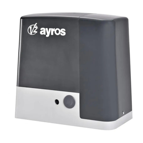
V2 STARK3-230V User manual

IL 493
EDIZ. 20/03/2022
STARK3
P
ACTUADOR
ELECTROMECÂNICO
IRREVERSÍVEL
PARA PORTÕES DE BATENTE
D
NICHT UMKEHRBARER
ELEKTROMECHANISCHER
ANTRIEB FÜR FLÜGELTORE
NL
ELEKTROMECHANISCHE,
ONOMKEERBARE LINEAIRE
MOTOR VOOR HEKKEN MET
VLEUGELS
PL
ELEKTROMECHANICZNY
NIEODWRACALNY SIŁOWNIK
DO BRAM SKRZYDŁOWYCH
I
ATTUATORE
ELETTROMECCANICO
IRREVERSIBILE PER CANCELLI
A BATTENTE
GB
IRREVERSIBLE
ELECTROMECHANICAL
ACTUATOR FOR SWING GATES
F
OPERATEUR
ELECTROMECANIQUE
IRREVERSIBLE POUR
PORTAILS BATTANTS
E
OPERADOR
ELECTROMECÁNICO
IRREVERSIBLE PARA
CANCELAS BATIENTES

820
100 110

ITALIANO
- 1 -
AVVERTENZE IMPORTANTI
mE’ necessario leggere tutte le istruzioni prima di
procedere all’installazione in quanto forniscono importanti
indicazioni riguardanti la sicurezza, l’installazione, l’uso e la
manutenzione.
L’AUTOMAZIONE DEVE ESSERE REALIZZATA IN CONFORMITÀ
VIGENTI NORMATIVE EUROPEE:
EN 60204-1, EN 12453, EN 13241-1, EN 12635
• L’installatore deve provvedere all’installazione di un dispositivo
(es. interruttore magnetotermico) che assicuri il sezionamento
onnipolare del sistema dalla rete di alimentazione.
La normativa richiede una separazione dei contatti di almeno
3 mm in ciascun polo (EN 60335-1).
• Per la connessione di tubi rigidi e flessibili o passacavi utilizzare
raccordi conformi al grado di protezione IP44 o superiore.
• L’installazione richiede competenze in campo elettrico e
meccanico; deve essere eseguita solamente da personale
qualificato in grado di rilasciare la dichiarazione di conformità
di tipo A sull’installazione completa (Direttiva macchine
2006/42/CEE, allegato IIA).
• Anche l’impianto elettrico a monte dell’automazione deve
rispondere alle vigenti normative ed essere eseguito a regola
d’arte.
• Consigliamo di utilizzare un pulsante di emergenza da
installare nei pressi dell’automazione (collegato all’ingresso
STOP della scheda di comando) in modo che sia possibile
l’arresto immediato del cancello in caso di pericolo.
• Per una corretta messa in servizio del sistema consigliamo di
seguire attentamente le indicazioni rilasciate dall’associazione
UNAC.
• Il presente manuale di istruzioni è destinato solamente a
personale tecnico qualificato nel campo delle installazioni di
automazioni.
• Nessuna delle informazioni contenute all’interno del manuale
può essere interessante o utile per l’utilizzatore finale.
• Qualsiasi operazione di manutenzione o di programmazione
deve essere eseguita esclusivamente da personale qualificato.
• Tutto quello che non è espressamente previsto in queste
istruzioni non è permesso; usi non previsti possono essere
fonte di pericolo per persone e cose.
• Non installare il prodotto in ambiente e atmosfera esplosivi:
presenza di gas o fumi infiammabili costituiscono un grave
pericolo per la sicurezza.
• Non eseguire modifiche su nessuna parte dell’automatismo o
degli accessori ad esso collegati se non previste nel presente
manuale.
• Qualsiasi altra modifica farà decadere la garanzia sul prodotto.
• Le fasi di installazione vanno eseguite evitando giornate
piovose che possono esporre le schede elettroniche a dannose
penetrazioni di acqua.
• Evitare di esporre l’automatismo vicino a fonti di calore e
fiamme.
• Qualora si verifichino interventi di interruttori automatici,
differenziali o di fusibili, prima del ripristino è necessario
individuare ed eliminare il guasto.
• Nel caso di guasto non risolvibile facendo uso delle
informazioni riportate nel presente manuale, interpellare il
servizio di assistenza V2.
• V2 declina qualsiasi responsabilità dall’inosservanza delle
norme costruttive di buona tecnica nonché dalle deformazioni
strutturali del cancello che potrebbero verificarsi durante l’uso.
• V2 si riserva il diritto di apportare eventuali modifiche al
prodotto senza preavviso.
• Gli addetti ai lavori di installazione \ manutenzione devono
indossare attrezzature di protezione individuale (DPI), quali
tute, caschi, stivali e guanti di sicurezza.
• La temperatura ambiente di lavoro deve essere quella indicata
nella tabella delle caratteristiche tecniche.
• L’automazione deve essere spenta immediatamente al
verificarsi di qualsiasi situazione anomala o di pericolo; il
guasto o malfunzionamento deve essere immediatamente
segnalato al funzionario responsabile.
• Tutti gli avvisi di sicurezza e di pericolo sulla macchina e le
attrezzature devono essere rispettati.
• Gli attuatori elettromeccanici per cancelli non sono destinati
ad essere utilizzati da persone (bambini compresi) con ridotte
capacità fisiche, sensoriali o mentali, o con mancanza di
esperienza e conoscenza, a meno che non siano sorvegliate
o siano state istruite sull’uso dell’attuatore da una persona
responsabile della loro sicurezza.
V2 si riserva il diritto di apportare eventuali modifiche
al prodotto senza preavviso; inoltre declina ogni
responsabilità per danni a persone o cose dovuti ad un uso
improprio o ad un’errata installazione.
SMALTIMENTO
Come per le operazioni d’installazione, anche al termine della
vita di questo prodotto, le operazioni di smantellamento devono
essere eseguite da personale qualificato. Questo prodotto è
costituito da vari tipi di materiali: alcuni possono essere riciclati,
altri devono essere smaltiti. Informatevi sui sistemi di riciclaggio o
smaltimento previsti dai regolamenti vigenti nel vostro territorio,
per questa categoria di prodotto.
Attenzione! – Alcune parti del prodotto possono contenere
sostanze inquinanti o pericolose che, se disperse nell’ambiente,
potrebbero provocare effetti dannosi sull’ambiente stesso e sulla
salute umana.
Come indicato dal simbolo a lato, è vietato gettare questo
prodotto nei rifiuti domestici. Eseguire quindi la “raccolta
separata” per lo smaltimento, secondo i metodi previsti dai
regolamenti vigenti sul vostro territorio, oppure riconsegnare
il prodotto al venditore nel momento dell’acquisto di un nuovo
prodotto equivalente.
Attenzione! – i regolamenti vigenti a livello locale possono
prevedere pesanti sanzioni in caso di smaltimento abusivo di
questo prodotto.
ASSISTENZA TECNICA
Per chiarimenti tecnici o problemi di installazione potete utilizzare
il Servizio Clienti al Numero Verde 800-134908 attivo dal lunedì al
venerdì dalle 8:30 alle 12:30 e dalle 14:00 alle 18:00.

ITALIANO
- 2 -
VERIFICHE PRELIMINARI E IDENTIFICAZIONE DELLA TIPOLOGIA DI UTILIZZO
Si ricorda che l’automatismo non sopperisce a difetti causati da una sbagliata installazione, o da una cattiva manutenzione, quindi, prima
di procedere all’installazione verificare che la struttura sia idonea e conforme alle norme vigenti e, se del caso, apportare tutte le modifiche
strutturali volte alla realizzazione dei franchi di sicurezza ed alla protezione o segregazione di tutte le zone di schiacciamento, cesoiamento,
convogliamento e verificare che:
• Il cancello deve essere equipaggiato di fermo centrale
• Il cancello non presenti punti d’attrito sia in chiusura che in apertura.
• Il cancello sia ben bilanciato, ossia fermato in qualsiasi posizione e non accenni a muoversi spontaneamente.
• La posizione individuata per il fissaggio del motoriduttore consenta una manovra manuale facile, sicura e compatibile
con l’ingombro del motoriduttore.
• Il supporto sul quale si effettua il fissaggio dell’automatismo sia solido e duraturo.
• La rete di alimentazione alla quale l’automatismo viene collegato sia dotata di messa a terra sicurezza e di interruttore differenziale
con corrente di intervento minore o uguale a 30mA dedicato all’automazione (la distanza d’apertura dei contatti deve essere uguale o
superiore a 3 mm).
Attenzione: Il livello minimo di sicurezza dipende dal tipo di utilizzo; fare riferimento al seguente schema:
GRUPPO 1 - Solo un limitato numero di persone è autorizzato all’uso, e la chiusura non è in un’area pubblica. Un esempio di questo tipo
sono i cancelli all’interno delle aziende, i cui fruitori sono solo i dipendenti o una parte di loro i quali sono stati adeguatamente informati.
GRUPPO 2 - Solo un limitato numero di persone è autorizzato all’uso, ma in questo caso la chiusura è in un’area pubblica. Un esempio può
essere un cancello aziendale che accede alla pubblica via, e che può essere utilizzato solo dai dipendenti.
GRUPPO 3 - Qualsiasi persona può utilizzare la chiusura automatizzata, che quindi è situata sul suolo pubblico. Ad esempio la porta di
accesso di un supermercato o di un ufficio, o di un ospedale.
PROTEZIONE A - La chiusura viene attivata tramite un pulsante di comando con la persona presente, cioè ad azione mantenuta.
PROTEZIONE B - La chiusura viene attivata tramite un comando con la persona presente, attraverso un selettore a chiave o simile, per
impedirne l’utilizzo a persone non autorizzate.
PROTEZIONE C - Limitazione delle forze dell’anta della porta o cancello. Cioè la forza di impatto deve rientrare in una curva stabilita dalla
normativa, nel caso il cancello colpisca un ostacolo.
PROTEZIONE D - Dispositivi, come le fotocellule, atte a rilevare la presenza di persone od ostacoli. Possono essere attivi su un solo lato o su
entrambi i lati della porta o cancello.
PROTEZIONE E - Dispositivi sensibili, come le pedane o le barriere immateriali, atti a rilevare la presenza di una persona, ed installati in
modo che questa non possa in alcun modo essere urtata dall’anta in movimento. Questi dispositivi devono essere attivi in tutta la “zona
pericolosa” del cancello. Per “zona pericolosa” la Direttiva Macchine intende una qualsiasi zona all’interno e/o in prossimità di una macchina
in cui la presenza di una persona esposta costituisca un rischio per la sicurezza e la salute di detta persona.
L’analisi dei rischi deve prendere in considerazione tutte le zone pericolose dell’automazione che dovranno essere
opportunamente protette e segnalate.
Applicare in una zona visibile una targa coni dati identificativi della porta o del cancello motorizzato.
L’installatore deve fornire tutte le informazioni relative al funzionamento automatico, apertura di emergenza della porta o
cancello motorizzati, alla manutenzione e consegnarle all’utilizzatore.
TIPOLOGIA DI UTILIZZO DELLA CHIUSURA
TIPOLOGIA DEI COMANDI DI
ATTIVAZIONE
GRUPPO 1
Persone informate
uso in area privata)
GRUPPO 2
Persone informate
(uso in area pubblica)
GRUPPO 3
Persone informate
(uso illimitato)
Comando a uomo presente A B Non è possibile
Comando a distanza e chiusura
in vista (es. infrarosso)
C oppure E C oppure E C e D oppure E
Comando a distanza e chiusura
non in vista (es. onde radio)
C oppure E C e D oppure E C e D oppure E
Comando automatico
(es. comando di chiusura
temporizzata)
C e D oppure E C e D oppure E C e D oppure E

ITALIANO
- 3 -
CARATTERISTICHE TECNICHE
STARK3-230V STARK3-24V
Lunghezza max anta m 3 3
Peso max anta Kg 600 600
Alimentazione 230Vac 24Vdc
Assorbimento a vuoto A 1 0,8
Assorbimento max A 1,6 15
Potenza elettrica W 200 120
Tempo apertura anta 0 ÷ 90° s 18,5 15
Corsa max di traino mm 360 (300) 360 (300)
Velocità di traino m/s 0,016 0,013 ÷ 0,016
Spinta max N 2000 2000
Temperatura d'esercizio °C -20 ÷ +55 -20 ÷ +55
Grado di protezione IP 44 44
Ciclo di lavoro % 30 90
Peso motore Kg 8 7
DICHIARAZIONE UE DI CONFORMITÀ E
DICHIARAZIONE DI INCORPORAZIONE
DI QUASI MACCHINA
Dichiarazione in accordo alle Direttive: 2014/35/UE (LVD);
2014/30/UE (EMC); 2006/42/CE (MD) ALLEGATO II, PARTE B
Il fabbricante V2 S.p.A., con sede in
Corso Principi di Piemonte 65, 12035, Racconigi (CN), Italia
Dichiara sotto la propria responsabilità che:
l’automatismo modello: STARK3-24V, STARK3-230V
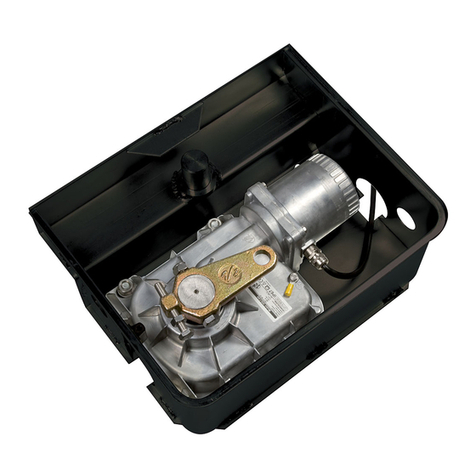
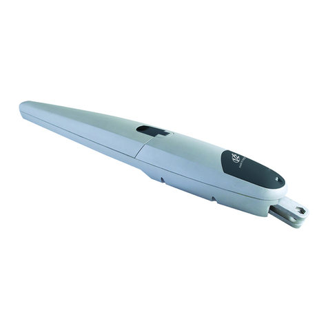
Descrizione: Attuatore elettromeccanico per cancelli a battente
• è destinato ad essere incorporato in un cancello a battente per
costituire una macchina ai sensi della Direttiva 2006/42/CE.
Tale macchina non potrà essere messa in servizio prima di
essere dichiarata conforme alle disposizioni delle direttive
2006/42/CE e 89/106/CE
• è conforme ai requisiti essenziali applicabili delle Direttive:
Direttiva Macchine 2006/42/CE (Allegato I, Capitolo 1)
Direttiva bassa tensione 2014/35/UE
Direttiva compatibilità elettromagnetica 2014/30/UE
Direttiva ROHS-3 2015/863/EU
La documentazione tecnica è a disposizione dell’autorità
competente su motivata richiesta presso: V2 S.p.A., Corso Principi
di Piemonte 65, 12035, Racconigi (CN), Italia
La persona autorizzata a firmare la presente dichiarazione di
incorporazione e a fornire la documentazione tecnica:
Sergio Biancheri
Rappresentante legale di V2 S.p.A.
Racconigi, il 01/06/2019
DESCRIZIONE DEL PRODOTTO
Il presente prodotto è destinato ad essere utilizzato per
automatizzare cancelli o portoni ad ante battenti, sia per uso
residenziale sia industriale.
mATTENZIONE!
Qualsiasi altro uso diverso da quello descritto e in condizioni
ambientali diverse da quelle riportate in questo manuale è da
considerarsi improprio e vietato!
Il prodotto è un motoriduttore elettromeccanico, provvisto di un
motore e di un riduttore con vite senza fine.
Il motoriduttore viene alimentato dalla centrale di comando
esterna a cui deve essere collegato.
In caso d’interruzione dell’energia elettrica (black-out), è possibile
muovere manualmente le ante del cancello sbloccando il
motoriduttore.

ITALIANO
- 4 -
SCHEMA DI INSTALLAZIONE
1 1D
E
3
A
C
2
56
4
A
B
C
D
E
1
2
3
4
5
6
Selettore chiave
Fotocellule a colonna
Selettore digitale via radio a colonna
Coste di sicurezza
Sistema ECO-LOGIC (solo con STARK3-24V e CITY2+)
Motore
Centrale di comando
Trasmettitore
Modulo ricevitore
Fotocellule
Lampeggiante
COMPONENTI ACCESSORI AGGIUNTIVI
LUNGHEZZA DEL CAVO < 10 metri da 10 a 20 metri da 20 a 30 metri
Alimentazione 230V 3G x 1,5 mm23G x 1,5 mm23G x 2,5 mm2
Alimentazione motore 24V 2G x 1,5 mm22G x 1,5 mm22G x 2,5 mm2
Alimentazione motore 230V 4G x 1,5 mm24G x 1,5 mm24G x 2,5 mm2
Fotocellule (TX) 2 x 0,5 mm22 x 0,5 mm22 x 0,5 mm2
Fotocellule (RX) 4 x 0,5 mm24 x 0,5 mm24 x 0,5 mm2
Selettore chiave 2 x 0,5 mm22 x 0,5 mm22 x 0,5 mm2
Costa di sicurezza 2 x 0,5 mm22 x 0,5 mm22 x 0,5 mm2
Lampeggiante 2 x 1,5 mm22 x 1,5 mm22 x 1,5 mm2
Antenna (integrata nel lampeggiante) RG174 RG174 RG174
ECO-LOGIC (box batteria) 2 x 1,5 mm2- -
ECO-LOGIC (pannello) 2 x 1 mm2- -
FIG.1

ITALIANO
- 5 -
MISURE DI INSTALLAZIONE
Per effettuare una corretta installazione degli operatori e garantire
un funzionamento ottimale dell’automazione è necessario
rispettare le misure riportate in tabella.
Eventualmente modificare la struttura del cancello in modo da
adattarlo ad uno dei casi riportati nella tabella.
g
gE [mm] A [mm]
90°
130 170
140 165
150 160
160 150
170 150
180 145
190 135
200 130
100°
130 155
140 150
150 145
160 140
170 140
180 135
110° 130 155
140 155
ALTEZZA DELLE STAFFE
Fissare le staffe con 54 mm di distanza tra i piani d’appoggio in
modo da ancorare il motoriduttore in posizione perfettamente
orizzontale.
FIG.3
FIG.2

ITALIANO
- 6 -
FISSAGGIO DEL MOTORIDUTTORE
ALLE STAFFE
Fissare il motoriduttore alla staffa posteriore (FIG. 4).
Fissare il motoriduttore alla staffa anteriore (FIG. 5).
MANOVRA MANUALE
Prima di eseguire la manovra manuale del motoriduttore togliere
l’eventuale alimentazione.
La manovra di sblocco è stata prevista per l’apertura manuale del
cancello in caso di mancanza di corrente o di avaria del motore.
• Inserire la chiave nella serratura del cilindro e ruotarla di 90° in
senso orario.
• Tirare la leva finché non è perpendicolare al motoriduttore.
RIPRISTINO DELL’AUTOMAZIONE
• Riportare la leva nella posizione originale.
• Inserire la chiave nella serratura del cilindro e ruotarla in senso
antiorario di 90°.
FIG.4 FIG.5
FIG.6
FIG.7

ITALIANO
- 7 -
COLLEGAMENTI ELETTRICI
mATTENZIONE
• Un collegamento errato può provocare guasti o si tuazioni di
pericolo; quindi, rispettare scrupolosamente i collegamenti
indicati.
• Eseguire le operazioni di collegamento con l’alimentazione
elettrica scollegata.
L’attuatore viene fornito con il connettore assemblato.
Smontare il connettore svitando la vite “A”, collegare quindi i fili
secondo lo schema riportato di seguito.
REGOLAZIONE DEL FINECORSA
Il finecorsa ha il compito di fermare il cancello in un punto
desiderato, evitando urti dell’anta sui fermi d’arresto.
• Portare il motoriduttore sul funzionamento manuale (FIG. 6).
• Allentare la vite del finecorsa meccanico (B).
• Portare l’anta nella posizione desiderata in completa apertura.
• Posizionare il finecorsa adiacente al perno di scorrimento (C),
facendolo agire da blocco.
• Riavvitare energicamente la vite.
• Ripristinare il funzionamento automatico del motoriduttore
(FIG. 7).
mATTENZIONE: i motoriduttori sono forniti di serie
con i finecorsa in apertura. In caso di mancanza di battute
in chiusura è possibile acquistare il fermo meccanico
opzionale.
STARK3-24V
1 - MOTORE (+)
2 - MOTORE (-)
3 - NON UTILIZZATO
- TERRA
STARK3-230V
1 - FASE 1
2 - FASE 2
3 - COMUNE
- TERRA
FIG.8
FIG.9
Per eseguire le verifiche dei collegamenti, del senso di
rotazione del motore, dello sfasamento del movimento
delle ante e della regolazione del finecorsa, fare riferimento
al manuale istruzioni della Centrale di comando.

ENGLISH
- 8 -
IMPORTANT REMARKS
mPrior to proceeding with installation, it is essential the
instructions be read in full, since they contain important
information regarding safety, installation, use and
maintenance.
AUTOMATION MUST BE IMPLEMENTED IN COMPLIANCE
WITH THE EUROPEAN REGULATIONS IN FORCE:
EN 60204-1, EN 12453, EN 13241-1, EN 12635
• The installer must provide for a device (es. magnetotermical
switch) ensuring the omnipolar sectioning of the equipment
from the power supply. The standards require a separation of
the contacts of at least 3 mm in each pole (EN 60335-1).
• The plastic case has an IP44 insulation; to connect flexible or
rigid pipes, use pipefittings having the same insulation level.
• Installation requires mechanical and electrical skills, therefore it
shall be carried out by qualified personnel only, who can issue
the Compliance Certificate concerning the whole installation
(Machine Directive 2006/42/CEE, Annex IIA).
• Also the automation upstream electric system shall
comply with the laws and rules in force and be carried out
workmanlike.
• We recommend to make use of an emergency button, to be
installed by the automation (connected to the control unit
STOP input) so that the gate may be immediately stopped in
case of danger.
• For correct installation of the system, we recommend
following the instructions issued by UNAC very carefully.
• This instruction manual is only for qualified technicians, who
specialize in installations and automations.
• The contents of this instruction manual do not concern the
end user.
• Every programming and/or every maintenance service should
be done only by qualified technicians.
• Anything not expressly described in these instructions is
prohibited; unforeseen uses may be a source of danger to
people and property.
• Do not install the product in explosive environments and
atmospheres: the presence of inflammable gases or fumes is a
serious safety hazard.
• Do not make any modifications to any part of the automation
device, or the accessories connected to it, unless described in
this manual.
• Any other modifications will void the warranty on the product.
• The installation steps should be conducted so as to avoid rainy
weather, which can expose electronic circuits to dangerous
water seepage.
• All operations requiring the casing of the device to opened
should be performed with the control unit disconnected from
the electricity supply and with a warning notice displayed, for
example: ”CAUTION, MAINTENANCE IN PROGRESS”.
• Avoid exposing the device close to sources of heat and flame.
• In the event of interventions on automatic or differential
breakers or fuses, it is essential that faults be identified and
resolved prior to resetting. In the case of faults that cannot
be resolved using the information to be found in this manual,
consult the V2 customer assistance service.
• V2 declines all responsibility for failure to comply with good
construction practice standards in addition to structural
deformation of the gate that might occur during use.
• V2 reserves the right to make modifications to the product
without prior warning.
• Installation/maintenance personnel should wear individual
protection devices (IPDs), such as overalls, safety helmets,
boots and gloves.
• The ambient operating temperature should be that indicated
in the technical characteristics table.
• The automation device should be shut down immediately in
the event of any anomalous or hazardous situation; the fault
or malfunction should be immediately reported to the person
responsible.
• All safety and hazard warnings on the machinery and
equipment should be complied with.
• Electromechanical actuators for gates are not intended to be
used by people (including children) with diminished physical,
sensory or mental capacity, or lacking in experience or
knowledge, unless they are under supervision or have been
instructed in use of the actuator by a person responsible for
safety.
V2 has the right to modify the product without previous
notice; it also declines any responsibility to damage or
injury to people or things caused by improper use or wrong
installation.
DISPOSAL OF THE PRODUCT
As for the installation operations, even at the end of this product’s
life span, the dismantling operations must be carried out by
qualified experts.
This product is made up of various types of materials: some can be
recycled while others need to be disposed of. Find out about the
recycling or disposal systems envisaged by your local regulations
for this product category.
Important! – Parts of the product could contain pollutants or
hazardous substances which, if released into the environment,
could cause harmful effects to the environment itself as well as to
human health.
As indicated by the symbol opposite, throwing away this product
as domestic waste is strictly forbidden. So dispose of it as
differentiated waste, in accordance with your local regulations,
or return the product to the retailer when you purchase a new
equivalent product.
Important! – the local applicable regulations may envisage heavy
sanctions in the event of illegal disposal of this product.
TECHNICAL SERVICE
For any installation problem please contact our Customer Service
at the number +39-0172.812411 operating Monday to Friday
from 8:30 to 12:30 and from 14:00 to 18:00.

ENGLISH
- 9 -
PRELIMINARY CHECKS AND IDENTIFICATION OF THE TYPE TO BE USED
It should be remembered that the device does not compensate for defects caused by improper installation, or poor maintenance, thus, prior
to proceeding with installation, ensure that the structure is suitable and meets current standards and, if necessary, perform any structural
modifications aimed at the implementation of safety gaps and the protection or segregation of all crushing, shearing and transit zones, and
verify that:
• Your gate is equipped with a central latch.
• The gate has no friction points, either during closing or opening.
• The gate is well balanced, i.e. there is no tendency to move spontaneously when stopped in any position.
• The position identified for fixing the motor reducer allows easy and safe manual manoeuvring, compatible with the
size of the motor reducer itself.
• The support on which the automation device will be fixed is solid and durable.
• The mains power supply to which the automation device is connected has a dedicated safety earthing system and differential breaker
with tripping current less than or equal to 30 mA (the breaker gap distance should be greater than or equal to 3 mm).
Warning: The minimum safety level depends on the type of use; please refer to the following outline:
GROUP 1 - Only a limited number of people are authorised for use, and closure is not in a public area. Examples of this type are gates inside
business premises, where the sole users are employees, or a part of them who have been suitably informed.
GROUP 2 - Only a limited number of people are authorised for use, but in this case, closure is in a public area. An example of this may be a
company gate that accesses onto a public street, and which is only used by employees.
GROUP 3 - Anyone can use the automated closure, which is thus located on public land. For example the access gate to a supermarket or
an office, or a hospital.
PROTECTION A - Closure is activated by means of a control button with the person present, i.e. with maintained action.
PROTECTION B - With the person present, closure is activated by a command controlled by means of a key-switch or the like, in order to
prevent use by unauthorised persons.
PROTECTION C - Restricts the force of the leaf of the door or gate. I.e., in the case of the gate striking an obstacle, the impact force must
fall within a curve established by the regulations.
PROTECTION D - Devices, such as photocells, capable of detecting the presence of people or obstacles. They may be active on just one side
or on both sides of the door or gate.
PROTECTION E - Sensitive devices, such as footboards or immaterial barriers, capable of detecting the presence of a person, and installed in
such a way that the latter cannot be struck in any way by a moving leaf or panel. These devices should be active within the entire “danger
zone” of the gate. The Machinery Directive defines “Danger Zone” as any zone surrounding and/or near machinery where the presence of
an exposed person constitutes a risk to the health and safety of that person.
The risk analysis should take into consideration all danger zones for the automation device, which should be appropriately
protected and marked.
In a clearly visible area, apply a sign with information identifying the motorised door or gate.
The installer should provide the user with all the information relating to automatic operation, emergency opening and
maintenance of the motorised door or gate.
CLOSURE USE TYPE
TYPE OF ACTIVATION
COMMANDS
GROUP 1
Informed people
(use in private area)
GROUP 2
Informed people
(use in public area)
GROUP 3
Informed people
(unlimited use)
Man-present command A B Not possible
Remote control and closure in
view (e.g. infrared)
C or E C or E C and D or E
Remote control and closure not
in view (e.g. radio)
C or E C and D or E C and D or E
Automatic control
(e.g. timed closure control)
C and D or E C and D or E C and D or E

ENGLISH
- 10 -
TECHNICAL DATA
STARK3-230V STARK3-24V
Max. leaf lenght m 3 3
Max. leaf weight Kg 600 600
Power supply 230Vac 24Vdc
Idling current A 1 0,8
Full load current A 1,6 15
Electric power W 200 120
Opening time of the leaf 0÷90° s 18,5 15
Max travel mm 360 (300) 360 (300)
Operating speed m/s 0,016 0,013 ÷ 0,016
Maximum thrust N 2000 2000
Working temperature °C -20 ÷ +55 -20 ÷ +55
Protection IP 44 44
Working cycle % 30 90
Motor weight Kg 8 7
DESCRIPTION OF THE PRODUCT
This product has been designed to automate gates or doors with
leaf opening, for residential or industrial use.
mCAUTION!
Any other use different to that described and in ambient
conditions different to those set out in this manual is to be
considered improper and forbidden!
The product is an electromechanical gear motor, equipped with
motor and an endless screw reduction gear.
The gear motor is powered by the external control unit to which it
is connected.
In the event of a black out, it is possible to move the gate leaves
by hand, unblocking the gear motor manually.
EU DECLARATION OF CONFORMITY
AND DECLARATION OF
INCORPORATION OF PARTLY
COMPLETED MACHINE
Declaration in accordance with Directives: 2014/35/UE (LVD);
2014/30/UE (EMC); 2006/42/CE (MD) ANNEX II, PART B
The manufacturer V2 S.p.A., headquarters in Corso Principi di
Piemonte 65, 12035, Racconigi (CN), Italy
Under its sole responsibility hereby declares that:
the partly completed machinery model(s):
STARK3-24V, STARK3-230V
Description: electromechanical actuator for gates
• is intended to be installed on gates, to create a machine
according to the provisions of the Directive 2006/42/EC.
The machinery must not be put into service until the final
machinery into which it has to be incorporated has been
declared in conformity with the provisions of the Directive
2006/42/EC and 89/106/CE.
• is compliant with the applicable essential safety requirements
of the following Directives:
Machinery Directive 2006/42/EC (annex I, chapter 1)
Low Voltage Directive 2014/35/EU
Electromagnetic Compatibility Directive 2014/30/EU
Directive ROHS-3 2015/863/EU
The relevant technical documentation is available at the national
authorities’ request after justifiable request to: V2 S.p.A., Corso
Principi di Piemonte 65, 12035, Racconigi (CN), Italia
The person empowered to draw up the declaration and to provide
the technical documentation:
Sergio Biancheri
Legal representative of V2 S.p.A.
Racconigi 01/06/2019

ENGLISH
- 11 -
INSTALLATION LAYOUT
1 1D
E
3
A
C
2
56
4
A
B
C
D
E
1
2
3
4
5
6
Key switch
Pillar photocells
Pillar-mounted digital radio switch
Safety edges
ECO-LOGIC system (only with STARK3-24V and CITY2+)
Motor
Control unit
Transmitter
Receiving module
Photocells
Flashing light
COMPONENTS ADDITIONAL ACCESSORIES
LENGTH OF THE CABLE < 10 metres from 10 to 20 metres from 20 to 30 metres
Power supply (230V) 3G x 1,5 mm23G x 1,5 mm23G x 2,5 mm2
24V motor power supply 2G x 1,5 mm22G x 1,5 mm22G x 2,5 mm2
230V motor power supply 4G x 1,5 mm24G x 1,5 mm24G x 2,5 mm2
Photocells (TX) 2 x 0,5 mm22 x 0,5 mm22 x 0,5 mm2
Photocells (RX) 4 x 0,5 mm24 x 0,5 mm24 x 0,5 mm2
Key switch 2 x 0,5 mm22 x 0,5 mm22 x 0,5 mm2
Safety edges 2 x 0,5 mm22 x 0,5 mm22 x 0,5 mm2
Flashing light 2 x 1,5 mm22 x 1,5 mm22 x 1,5 mm2
Antenna (integrated into the flashing light) RG174 RG174 RG174
ECO-LOGIC (accumulator unit) 2 x 1,5 mm2- -
ECO-LOGIC (solar panel) 2 x 1 mm2- -
FIG.1

ENGLISH
- 12 -
g
gE [mm] A [mm]
90°
130 170
140 165
150 160
160 150
170 150
180 145
190 135
200 130
100°
130 155
140 150
150 145
160 140
170 140
180 135
110° 130 155
140 155
FIG.2
BRACKETS HEIGHT
Fix the brackets keeping 54 mm between the surfaces in order
tofix the gear-motor horizontally. (FIG.3).
INSTALLATION MEASURES
To carry out a proper installation of the operator parts as well as
to ensure the best automation performance, the measurement
levels shown in the following table shall be complied with.
Change the gate structure to adapt it to one of the cases in the
table, if necessary.
FIG.3

ENGLISH
- 13 -
FIXING THE GEAR-MOTOR TO THE
BRACKETS
Fixing the gear-motor to the rear brackets. (FIG. 4).
Fixing the gear-motor to the front brackets (FIG. 5).
MANUAL OVERRIDE
Before operating the manual override disconnect the power.
Manual override has been thought for manual opening of the
gate in case of power-cut or motor breakdown.
• Insert the key in the cylinder lock and turn it of 90° clockwise
direction.
• Pull the lever till it is perpendicular to the gear-motor
RESTORE
• Bring back the lever in the original position.
• Inser the key in the cylinder lock and turn it of 90°
anticlockwise direction.
FIG.4 FIG.5
FIG.6
FIG.7

ENGLISH
- 14 -
ELECTRICAL CONNECTION
mCAUTION!
• A wrong connection can cause faults or danger; therefore
follow scrupulously the connections set out.
• Perform the connection operations when the electricity is off.
The actuator is provided with the assembled connector.
Disassemble the connector by unscrewing the screw “A”, then
connect the wires according to the diagram below.
STOP ADJUSTMENT
The mechanical-stop enables to stop the gate at a required
position, avoiding the door to hit the stop devices.
• Set the gear-motor on manual override (FIG. 6).
• Twist off the screw of the mechanical-stop (B or D).
• Move the door to the desired opening/closing position.
• Place the mechanical-stop next to the sliding pin (C).
• Turn the screw tightly.
• Set the gear-motor on automatic functioning (FIG. 7).
mWARNING: The gear-motors are normally provided
with mechanical stop in open position. In case of lack of
external mechanical stop in closing position, it is possible to
buy the optional mechanical stop.
FIG.8
FIG.9
STARK3-24V
1 - MOTOR (+)
2 - MOTOR (-)
3 - NOT USED
- GROUND
STARK3-230V
1 - PHASE 1
2 - PHASE 2
3 - COMMON
- GROUND
To check the connections, direction of rotation of the motor,
phase shift in the movement of the leaves and setting the
limit switch, refer to the instructions manual of the control
unit.

FRANÇAIS
- 15 -
CONSEILS IMPORTANTS
mV2 se réserve le droit d’apporter d’éventuelles
modifications au produit sans préavis; elle décline en outre
toute responsabilité pour tous types de dommages aux
personnes ou aux choses dus à une utilisation imporopre ou
à une mauvaise installation.
L’AUTOMATION DOIT ÊTRE RÉALISÉE CONFORMÉMENT AUX
DISPOSITIFS NORMATIFS EUROPÉENS EN VIGUEUR:
EN 60204-1, EN 12453, EN 13241-1, EN 12635
• L’installateur doit pourvoir à l’installation d’un dispositif
(ex. interrupteur magnétothermique) qui assure la coupure
omnipolaire de l’équipement du réseau d’alimentation.
La norme requiert une séparation des contacts d’au moins
3 mm pour chaque pôle (EN 60335-1).
• L’enveloppe en plastique de la carte possède une protection
IP44, pour la connexion de tubes rigides ou flexibles utiliser
des raccordements possédant le même niveau de protection.
• L’installation requiert des compétences en matière d’électricité
et mécaniques; doit être faite exclusivement par techniciens
qualifiés en mesure de délivrer l’attestation de conformité
pour l’installation (Directive 2006/42/CEE, - IIA).
• Même l’installation électrique ou on branche l’automatisme
doit répondre aux normesen vigueur et être fait à règles de
l’art.
• Nous conseillons d’utiliser un poussoir d’urgence à installer
près de l’automatisme (branché à l’entrée STOP de l’armoire
de commande de façon qui soit possible l’arrêt immédiat du
portail en cas de danger.
• Pour une correcte mise en service du système nous conseillons
de suivre attentivement les indications fournies par
l’association UNAC.
• Ce manuel d’instruction est destiné à des techniciens qualifiés
dans le domain des automatismes.
• Aucune des informations contenues dans ce livret pourra être
utile pour le particulier.
• Tous operations de maintenance ou programation doivent être
faites à travers de techniciens qualifiés.
• Toutes les interventions ou réparations non expressément
prévues dans le présent manuel ne sont pas autorisées;
Tout usage non prévu peut être source de danger pour les
personnes ou les choses.
• Ne pas installer le produit en atmosphère et environnement
explosifs: la présence de gaz ou de fumées inflammables
constitue un grave danger pour la sécurité.
• Ne pas exécuter de modifications sur aucune partie de
l’automatisme ou sur ses accessoires si cela n’est prévu dans le
présent manuel.
• Toute autre modification fera déchoir la garantie du produit.
• Les phases d’installation doivent être exécutées en évitant
les journées pluvieuses susceptibles d’exposer les cartes
électroniques à des pénétrations d’eau nuisibles.
• Toutes les opérations nécessitant l’ouverture des coques
de l’automatisme doivent être effectuées avec l’armoire de
commande débranchée et faire l’objet d’une signalétique
d’avertissement, par exemple: ”ATTENTION ENTRETIEN EN
COURS”.
• Éviter d’exposer l’automatisme à proximité de sources de
chaleur et de flammes.
• En cas d’interventions sur interrupteurs automatiques,
différentiels ou fusibles, il est nécessaire de déterminer et
d’éliminer la panne avant de procéder au rétablissement
• En cas de panne ne pouvant être résolue en utilisant les
renseignements dans le présent Manuel, contactez le service
assistance V2.
• V2 décline toute responsabilité concernant le non respect
des normes constructives de bonne technique ainsi que des
déformations structurelles du portail qui pourrait se vérifier
durant l’usage.
• V2 se réserve le droit d’apporter d’éventuelles modifications
au produit sans préavis.
• Les préposés aux travaux d’installation \ entretien doivent se
doter d’équipements de protection individuelle (EPI), tels que:
combinaisons de travail, casques, bottes et gants de sécurité.
• La température ambiante de travail doit être celle indiquée
dans le tableau des caractéristiques techniques.
• L’automation doit être éteinte immédiatement si toute
situation anomale ou de danger a lieu; la panne ou le mauvais
fonctionnement doit être signalé immédiatement au dirigeant
responsable.
• Tous les avis de sécurité et de danger sur la machine et les
équipements doivent être respectés.
• Les actionneurs électromécaniques pour portails ne sont
pas destinés à être utilisés par des personnes (y compris
les enfants) dont les capacités physiques, sensorielles ou
mentales sont limitées, ou sans expérience et connaissance,
à moins qu’ils ne soient surveillés ou n’aient reçu des
instructions d’une personne responsable de leur sécurité.
V2 se réserve le droit d’apporter d’éventuelles modifications
au produit sans préavis; elle décline en outre toute
responsabilité pour tous types de dommages aux personnes
ou aux choses dus à une utilisation imporopre ou à une
mauvaise installation.
ÉLIMINATION DU PRODUIT
Comme pour les opérations d’installation, même à la fin de la
vie de ce produit, les opérations de démantèlement doivent être
effectuées par un personnel qualifié. Ce produit est composé
de différents types de matériaux: certains peuvent être recyclés,
d’autres doivent être éliminés. S’informer sur les systèmes de
recycla ge ou de mise au rebut prévus par les règlements en
vigueur sur le territoire, pour cette catégorie de produit.
Attention ! – Certaines parties du produit peuvent contenir des
substances polluantes ou dangereuses qui, si dispersées dans
l’environnement, pourraient provoquer des effets nocifs sur
l’environnement et sur la santé humaine.
Comme indiqué par le symbole ci-contre, il est interdit de jeter
ce produit dans les déchets domestiques. Effectuer une “collecte
séparée” pour la mise au rebut, selon les méthodes prévues par
les règlements en vigueur sur le territoire, ou amener le produit au
vendeur au moment de l’achat d’un nouveau produit équivalent.
Attention ! – les règlements en vigueur au niveau local peuvent
prévoir de lourdes sanctions en cas de mise au rebut abusif de ce
produit.
SERVICE D’ASSISTANCE
TECHNIQUE
Pour tout précision technique ou problème d’installation V2
dispose d’un Service Clients à Votre disposition du lundi au
vendredi de 8:30 à 12:30 et de 14:00 heures à 18:00 heures. au
numéro +39-0172.812411

FRANÇAIS
- 16 -
VÉRIFICATIONS PRÉLIMINAIRES ET IDENTIFICATION DE LA TYPOLOGIE
D’UTILISATION
Nous rappelons que l’automatisme ne pallie pas les défauts causés par une installation erronée, ou relatifs à un mauvais entretien, par
conséquent, avant de procéder à l’installation, vérifier que la structure soit adaptée et conforme aux normes en vigueur et, le cas échéant,
procéder aux modifications structurelles destinées à la réalisation des barrières de sécurité et à la protection ou isolation de toutes les zones
d’écrasement, cisaillement, entraînement et vérifier que:
• Votre portail doit être équipé d’arrêt centraux.
• Le portail ne présente pas de points de frottement à la fermeture ou à l’ouverture.
• Le portail soit correctement équilibré, c’est-à-dire arrêté dans une position quelconque sans déplacement spontanés.
• La position déterminée pour la fixation du motoréducteur permette une manœuvre manuelle facile, sûre et compatible avec
l’encombrement du motoréducteur.
• Le support sur lequel la fixation de l’automatisme est effectuée soit solide et durable.
• Le réseau d’alimentation auquel l’automatisme est relié soit équipé d’une mise à la terre de sécurité et d’interrupteur différentiel avec
courant d’intervention inférieur ou égal à 30mA dédié spécialement à l’automation (la distance d’ouverture des contacts doit être égale
ou supérieure à 3 mm).
Attention: Le niveau minimum de sécurité dépend du type d’utilisation; se référer au schéma suivant:
GROUPE 1 - Seul un nombre limité de personnes est autorisé à l’usage, et la fermeture ne se situe pas dans une zone publique. On peut
citer comme exemple de ce type, les portails à l’intérieur des sociétés, dont les utilisateurs sont les seuls employés ou partie d’entre eux, et
ont été spécialement informés.
GROUPE 2 - Seul un nombre limité de personnes est autorisé à l’usage, mais dans ce cas la fermeture se trouve dans une zone publique. On
peut citer comme exemple le portail d’une entreprise permettant l’accès à une route publique et pouvant être utilisé exclusivement par les
employés de ladite entreprise.
GROUPE 3 - La fermeture automatisée du portail peut être utilisée par quiconque, elle est donc située sur un sol public. Par exemple, la
porte d’accès d’un supermarché, d’un bureau, ou d’un hôpital.
PROTECTION A - La fermeture est activée à l’aide d’un bouton de commande avec la personne présente, il s’agit d’une action prévoyant le
maintien enfoncé du bouton.
PROTECTION B - La fermeture est activée à l’aide d’une commande nécessitant la présence de la personne, par l’intermédiaire d’un
sélecteur à clé ou similaire, afin d’en empêcher l’usage par des personnes non autorisées.
PROTECTION C - Limitation des forces du vantail de la porte ou du portail. À savoir, la force d’impact doit être comprise dans une courbe
établie en fonction de la norme en vigueur, au cas où le portail rencontrerait un obstacle.
PROTECTION D - Dispositifs tels que des photocellules, capables de relever la présence de personnes ou d’obstacles. Ils peuvent être activés
sur un ou deux côtés de la porte ou du portail.
PROTECTION E - Dispositifs sensibles tels que les estrades ou les barrières immatérielles, capables de relever la présence d’une personne,
et installés de manière à ce que celle-ci ne puisse en aucun cas être heurtée par la porte en mouvement. Ces dispositifs doivent être activés
dans l’intégralité de la “zone dangereuse” du portail. Par “zone dangereuse”, la Directive Machines entend toute zone située à l’intérieur
et/ou à proximité d’une machine dans laquelle la présence d’une personne exposée constitue un risque pour sa propre sécurité et santé.
L’analyse des risques doit prendre en considération toutes les zones dangereuses de l’automation lesquelles devront faire
l’objet d’installation de protection et de signalétique adaptées.
Une plaque comportant les données d’identification de la porte ou du portail motorisé doit être positionnée de façon bien visible.
L’installateur doit fournir à l’utilisateur toutes les informations relatives au fonctionnement automatique, à l’ouverture
d’urgence de la porte ou du portail motorisé et à l’entretien.
TYPOLOGIE D’UTILISATION DE LA FERMETURE
TYPOLOGIE DES COMMANDES
D’ACTIVATION
GROUPE 1
Personnes informées
(usage en zone privée)
GROUPE 2
Personnes informées
(usage en zone publique)
GROUPE 3
Personnes informées
(usage illimité)
Commandes de type "homme mort" A B Impossible
Commande à distance et fermeture à
vue (ex. infrarouge)
C ou bien E C ou bien E C et D ou bien E
Commande à distance et fermeture
hors vue (ex.ondes radio)
C ou bien E C et D ou bien E C et D ou bien E
Commande automatique (ex.
commande de fermeture temporisée)
C et D ou bien E C et D ou bien E C et D ou bien E

FRANÇAIS
- 17 -
CARACTERISTIQUES TECHNIQUES
STARK3-230V STARK3-24V
Longuer maxi du battant m 3 3
Poids maxi du battant Kg 600 600
Alimentation 230Vac 24Vdc
Absorption à vide A 1 0,8
Absorption maximum A 1,6 15
Puissance électrique W 200 120
Temps ouverture vantail 0 ÷ 90° s 18,5 15
Course maxi d’entrainement mm 360 (300) 360 (300)
Vitesse de traction m/s 0,016 0,013 ÷ 0,016
Pousée maximum N 2000 2000
Température de service °C -20 ÷ +55 -20 ÷ +55
Indìce de protection IP 44 44
Cycle de travail % 30 90
Poids moteur Kg 8 7
DECLARATION UE DE CONFORMITE ET
DECLARATION D’INCORPORATION DE
QUASI-MACHINE
Déclaration en accord avec les Directives: 2014/35/UE (LVD);
2014/30/UE (EMC); 2006/42/CE (MD) ANNEXE II, PARTIE B
The manufacturer V2 S.p.A., headquarters in Corso Principi di
Piemonte 65, 12035, Racconigi (CN), Italy
Déclare sous sa propre responsabilité que:
l’automatisme modèle: STARK3-24V, STARK3-230V
Description: actionneur électromécanique pour portails
• a été conçu pour être incorporé dans un portail garage en vue
de former une machine conformément à la Directive
2006/42/CE. Cette machine ne pourra pas être mise en service
avant d’être déclarée conforme aux dispositions des directives
2006/42/CE et 89/106/CE.
• est conforme exigences essentielles applicables des Directives:
Directive Machines 2006/42/CE (Annexe I, Chapitre 1)
Directive basse tension 2014/35/UE
Directive compatibilité électromagnétique 2014/30/UE
Directive ROHS-3 2015/863/EU
La documentation technique est à disposition de l’autorité
compétente sur demande motivée à l’adresse suivante:
V2 S.p.A., Corso Principi di Piemonte 65, 12035, Racconigi (CN),
Italia
La personne autorisée à signer la présente déclaration
d’incorporation et à fournir la documentation technique est :
Sergio Biancheri
Représentant légal de V2 S.p.A.
Racconigi, 01/06/2019
DESCRIPTION DU PRODUIT
Ce produit est à utiliser pour l’automation des grilles ou portails à
vantaux battants de type résidentiel ou industriel.
mATTENTION!
Toute autre utilisation que celle indiquée ou dans des conditions
ambiantes différentes de celles signalées dans cette notice sera
considérée comme inadéquate et de ce fait interdite!
Le produit est un motoréducteur électromécanique, équipé d’un
moteur et d’un réducteur muni de vis sans fin.
Le motoréducteur est alimenté par la Centrale de commande
externe à laquelle il doit être relié.
En cas de coupure de l’alimentation électrique (black-out), il est
possible de manoeuvrer “à la main” les vantaux du portail en
déverrouillant manuellement le motoréducteur.

FRANÇAIS
- 18 -
SCHÉMA D’INSTALLATION
1 1D
E
3
A
C
2
56
4
A
B
C
D
E
1
2
3
4
5
6
Sélecteur à clé
Potelets avec photocellules
Sélecteur digitale par radio à colonne
Barres palpeuses de sécurité
Système ECO-LOGIC (seul avec STARK3-24V et CITY2+)
Vérin
Armoire de commande
Émetteur
Module récepteur
Photocellules
Feu
COMPOSANTS AUTRES ACCESSOIRES
LONGUEUR DU CÂBLE < 10 metri da 10 a 20 metri da 20 a 30 metri
Alimentation 230V 3G x 1,5 mm23G x 1,5 mm23G x 2,5 mm2
Alimentation moteur 24V 2G x 1,5 mm22G x 1,5 mm22G x 2,5 mm2
Alimentation moteur 230V 4G x 1,5 mm24G x 1,5 mm24G x 2,5 mm2
Photocellules (TX) 2 x 0,5 mm22 x 0,5 mm22 x 0,5 mm2
Photocellules (RX) 4 x 0,5 mm24 x 0,5 mm24 x 0,5 mm2
Sélecteur à clé 2 x 0,5 mm22 x 0,5 mm22 x 0,5 mm2
Barres palpeuses de sécurité 2 x 0,5 mm22 x 0,5 mm22 x 0,5 mm2
Feu 2 x 1,5 mm22 x 1,5 mm22 x 1,5 mm2
Antenne (intégrée dans le feu) RG174 RG174 RG174
ECO-LOGIC (groupe accumulateur) 2 x 1,5 mm2- -
ECO-LOGIC (panneau solaire) 2 x 1 mm2- -
FIG.1
This manual suits for next models
2
Table of contents
Languages:
Other V2 Controllers manuals
Popular Controllers manuals by other brands

Swagelok
Swagelok KFB Series Maintenance instructions

Danfoss
Danfoss ERC 112D VSC user guide

Siegenia
Siegenia Drive Connect Box Installation and operating instructions

Beam Labs
Beam Labs Pixelator Plus product manual

KIPI
KIPI ecoMAX860P3-C Installation and operating manual

Salus
Salus PCSol 201 Installation and operation manual