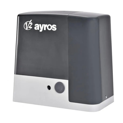
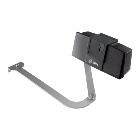
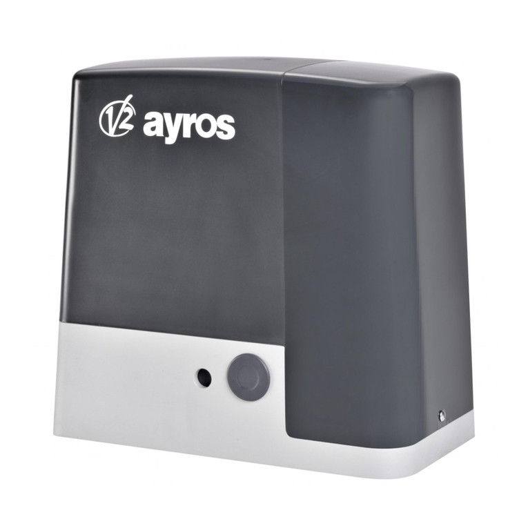
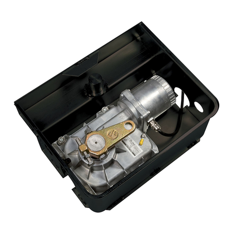
V2 STARK6 User manual

IL 494
EDIZ. 04/03/2020
STARK6
ATTUATORE ELETTROMECCANICO IRREVERSIBILE
PER CANCELLI A BATTENTE
IRREVERSIBLE ELECTROMECHANICAL ACTUATOR
FOR SWING GATES
OPERATEUR ELECTROMECANIQUE IRREVERSIBLE
POUR PORTAILS BATTANTS
OPERADOR ELECTROMECÁNICO IRREVERSIBLE
PARA CANCELAS BATIENTES
NICHT UMKEHRBARER ELEKTROMECHANISCHER
ANTRIEB FÜR FLÜGELTORE
ELEKTROMECHANISCHE, ONOMKEERBARE LINEAIRE
MOTOR VOOR HEKKEN MET VLEUGELS
I
GB
F
E
D
NL

117 1030
110

ITALIANO
- 1 -
AVVERTENZE IMPORTANTI
mE’ necessario leggere tutte le istruzioni prima di
procedere all’installazione in quanto forniscono importanti
indicazioni riguardanti la sicurezza, l’installazione, l’uso e la
manutenzione.
L’AUTOMAZIONE DEVE ESSERE REALIZZATA IN CONFORMITÀ
VIGENTI NORMATIVE EUROPEE:
EN 60204-1, EN 12453, EN 13241-1, EN 12635
• L’installatore deve provvedere all’installazione di un dispositivo
(es. interruttore magnetotermico) che assicuri il sezionamento
onnipolare del sistema dalla rete di alimentazione.
La normativa richiede una separazione dei contatti di almeno
3 mm in ciascun polo (EN 60335-1).
• Per la connessione di tubi rigidi e flessibili o passacavi utilizzare
raccordi conformi al grado di protezione IP44 o superiore.
• L’installazione richiede competenze in campo elettrico e
meccanico; deve essere eseguita solamente da personale
qualificato in grado di rilasciare la dichiarazione di conformità
di tipo A sull’installazione completa (Direttiva macchine
2006/42/CEE, allegato IIA).
• Anche l’impianto elettrico a monte dell’automazione deve
rispondere alle vigenti normative ed essere eseguito a regola
d’arte.
• Consigliamo di utilizzare un pulsante di emergenza da
installare nei pressi dell’automazione (collegato all’ingresso
STOP della scheda di comando) in modo che sia possibile
l’arresto immediato del cancello in caso di pericolo.
• Per una corretta messa in servizio del sistema consigliamo di
seguire attentamente le indicazioni rilasciate dall’associazione
UNAC.
• Il presente manuale di istruzioni è destinato solamente a
personale tecnico qualificato nel campo delle installazioni di
automazioni.
• Nessuna delle informazioni contenute all’interno del manuale
può essere interessante o utile per l’utilizzatore finale.
• Qualsiasi operazione di manutenzione o di programmazione
deve essere eseguita esclusivamente da personale qualificato.
• Tutto quello che non è espressamente previsto in queste
istruzioni non è permesso; usi non previsti possono essere
fonte di pericolo per persone e cose.
• Non installare il prodotto in ambiente e atmosfera esplosivi:
presenza di gas o fumi infiammabili costituiscono un grave
pericolo per la sicurezza.
• Non eseguire modifiche su nessuna parte dell’automatismo o
degli accessori ad esso collegati se non previste nel presente
manuale.
• Qualsiasi altra modifica farà decadere la garanzia sul prodotto.
• Le fasi di installazione vanno eseguite evitando giornate
piovose che possono esporre le schede elettroniche a dannose
penetrazioni di acqua.
• Evitare di esporre l’automatismo vicino a fonti di calore e
fiamme.
• Qualora si verifichino interventi di interruttori automatici,
differenziali o di fusibili, prima del ripristino è necessario
individuare ed eliminare il guasto.
• Nel caso di guasto non risolvibile facendo uso delle
informazioni riportate nel presente manuale, interpellare il
servizio di assistenza V2.
• V2 declina qualsiasi responsabilità dall’inosservanza delle
norme costruttive di buona tecnica nonché dalle deformazioni
strutturali del cancello che potrebbero verificarsi durante l’uso.
• V2 si riserva il diritto di apportare eventuali modifiche al
prodotto senza preavviso.
• Gli addetti ai lavori di installazione \ manutenzione devono
indossare attrezzature di protezione individuale (DPI), quali
tute, caschi, stivali e guanti di sicurezza.
• La temperatura ambiente di lavoro deve essere quella indicata
nella tabella delle caratteristiche tecniche.
• L’automazione deve essere spenta immediatamente al
verificarsi di qualsiasi situazione anomala o di pericolo; il
guasto o malfunzionamento deve essere immediatamente
segnalato al funzionario responsabile.
• Tutti gli avvisi di sicurezza e di pericolo sulla macchina e le
attrezzature devono essere rispettati.
• Gli attuatori elettromeccanici per cancelli non sono destinati
ad essere utilizzati da persone (bambini compresi) con ridotte
capacità fisiche, sensoriali o mentali, o con mancanza di
esperienza e conoscenza, a meno che non siano sorvegliate
o siano state istruite sull’uso dell’attuatore da una persona
responsabile della loro sicurezza.
V2 si riserva il diritto di apportare eventuali modifiche
al prodotto senza preavviso; inoltre declina ogni
responsabilità per danni a persone o cose dovuti ad un uso
improprio o ad un’errata installazione.
SMALTIMENTO
Come per le operazioni d’installazione, anche al termine della
vita di questo prodotto, le operazioni di smantellamento devono
essere eseguite da personale qualificato. Questo prodotto è
costituito da vari tipi di materiali: alcuni possono essere riciclati,
altri devono essere smaltiti. Informatevi sui sistemi di riciclaggio o
smaltimento previsti dai regolamenti vigenti nel vostro territorio,
per questa categoria di prodotto.
Attenzione! – Alcune parti del prodotto possono contenere
sostanze inquinanti o pericolose che, se disperse nell’ambiente,
potrebbero provocare effetti dannosi sull’ambiente stesso e sulla
salute umana.
Come indicato dal simbolo a lato, è vietato gettare questo
prodotto nei rifiuti domestici. Eseguire quindi la “raccolta
separata” per lo smaltimento, secondo i metodi previsti dai
regolamenti vigenti sul vostro territorio, oppure riconsegnare
il prodotto al venditore nel momento dell’acquisto di un nuovo
prodotto equivalente.
Attenzione! – i regolamenti vigenti a livello locale possono
prevedere pesanti sanzioni in caso di smaltimento abusivo di
questo prodotto.
ASSISTENZA TECNICA
Per chiarimenti tecnici o problemi di installazione potete utilizzare
il Servizio Clienti al Numero Verde 800-134908 attivo dal lunedì al
venerdì dalle 8:30 alle 12:30 e dalle 14:00 alle 18:00.

ITALIANO
- 2 -
VERIFICHE PRELIMINARI E IDENTIFICAZIONE DELLA TIPOLOGIA DI UTILIZZO
Si ricorda che l’automatismo non sopperisce a difetti causati da una sbagliata installazione, o da una cattiva manutenzione, quindi, prima
di procedere all’installazione verificare che la struttura sia idonea e conforme alle norme vigenti e, se del caso, apportare tutte le modifiche
strutturali volte alla realizzazione dei franchi di sicurezza ed alla protezione o segregazione di tutte le zone di schiacciamento, cesoiamento,
convogliamento e verificare che:
• Il cancello deve essere equipaggiato di fermo centrale
• Il cancello non presenti punti d’attrito sia in chiusura che in apertura.
• Il cancello sia ben bilanciato, ossia fermato in qualsiasi posizione e non accenni a muoversi spontaneamente.
• La posizione individuata per il fissaggio del motoriduttore consenta una manovra manuale facile, sicura e compatibile
con l’ingombro del motoriduttore.
• Il supporto sul quale si effettua il fissaggio dell’automatismo sia solido e duraturo.
• La rete di alimentazione alla quale l’automatismo viene collegato sia dotata di messa a terra sicurezza e di interruttore differenziale
con corrente di intervento minore o uguale a 30mA dedicato all’automazione (la distanza d’apertura dei contatti deve essere uguale o
superiore a 3 mm).
Attenzione: Il livello minimo di sicurezza dipende dal tipo di utilizzo; fare riferimento al seguente schema:
GRUPPO 1 - Solo un limitato numero di persone è autorizzato all’uso, e la chiusura non è in un’area pubblica. Un esempio di questo tipo
sono i cancelli all’interno delle aziende, i cui fruitori sono solo i dipendenti o una parte di loro i quali sono stati adeguatamente informati.
GRUPPO 2 - Solo un limitato numero di persone è autorizzato all’uso, ma in questo caso la chiusura è in un’area pubblica. Un esempio può
essere un cancello aziendale che accede alla pubblica via, e che può essere utilizzato solo dai dipendenti.
GRUPPO 3 - Qualsiasi persona può utilizzare la chiusura automatizzata, che quindi è situata sul suolo pubblico. Ad esempio la porta di
accesso di un supermercato o di un ufficio, o di un ospedale.
PROTEZIONE A - La chiusura viene attivata tramite un pulsante di comando con la persona presente, cioè ad azione mantenuta.
PROTEZIONE B - La chiusura viene attivata tramite un comando con la persona presente, attraverso un selettore a chiave o simile, per
impedirne l’utilizzo a persone non autorizzate.
PROTEZIONE C - Limitazione delle forze dell’anta della porta o cancello. Cioè la forza di impatto deve rientrare in una curva stabilita dalla
normativa, nel caso il cancello colpisca un ostacolo.
PROTEZIONE D - Dispositivi, come le fotocellule, atte a rilevare la presenza di persone od ostacoli. Possono essere attivi su un solo lato o su
entrambi i lati della porta o cancello.
PROTEZIONE E - Dispositivi sensibili, come le pedane o le barriere immateriali, atti a rilevare la presenza di una persona, ed installati in
modo che questa non possa in alcun modo essere urtata dall’anta in movimento. Questi dispositivi devono essere attivi in tutta la “zona
pericolosa” del cancello. Per “zona pericolosa” la Direttiva Macchine intende una qualsiasi zona all’interno e/o in prossimità di una macchina
in cui la presenza di una persona esposta costituisca un rischio per la sicurezza e la salute di detta persona.
L’analisi dei rischi deve prendere in considerazione tutte le zone pericolose dell’automazione che dovranno essere
opportunamente protette e segnalate.
Applicare in una zona visibile una targa coni dati identificativi della porta o del cancello motorizzato.
L’installatore deve fornire tutte le informazioni relative al funzionamento automatico, apertura di emergenza della porta o
cancello motorizzati, alla manutenzione e consegnarle all’utilizzatore.
TIPOLOGIA DI UTILIZZO DELLA CHIUSURA
TIPOLOGIA DEI COMANDI DI
ATTIVAZIONE
GRUPPO 1
Persone informate
uso in area privata)
GRUPPO 2
Persone informate
(uso in area pubblica)
GRUPPO 3
Persone informate
(uso illimitato)
Comando a uomo presente A B Non è possibile
Comando a distanza e chiusura
in vista (es. infrarosso)
C oppure E C oppure E C e D oppure E
Comando a distanza e chiusura
non in vista (es. onde radio)
C oppure E C e D oppure E C e D oppure E
Comando automatico
(es. comando di chiusura
temporizzata)
C e D oppure E C e D oppure E C e D oppure E

ITALIANO
- 3 -
DICHIARAZIONE UE DI CONFORMITÀ E
DICHIARAZIONE DI INCORPORAZIONE
DI QUASI MACCHINA
Dichiarazione in accordo alle Direttive: 2014/35/UE (LVD);
2014/30/UE (EMC); 2006/42/CE (MD) ALLEGATO II, PARTE B
Il fabbricante V2 S.p.A., con sede in
Corso Principi di Piemonte 65, 12035, Racconigi (CN), Italia
Dichiara sotto la propria responsabilità che:
l’automatismo modello:
STARK6-24V
STARK6-230V
Descrizione: Attuatore elettromeccanico per cancelli a battente
• è destinato ad essere incorporato in un cancello a battente per
costituire una macchina ai sensi della Direttiva 2006/42/CE.
Tale macchina non potrà essere messa in servizio prima di
essere dichiarata conforme alle disposizioni delle direttive
2006/42/CE e 89/106/CE
• è conforme ai requisiti essenziali applicabili delle Direttive:
Direttiva Macchine 2006/42/CE (Allegato I, Capitolo 1)
Direttiva bassa tensione 2014/35/UE
Direttiva compatibilità elettromagnetica 2014/30/UE
Direttiva RoHS2 2011/65/CE
La documentazione tecnica è a disposizione dell’autorità
competente su motivata richiesta presso:
V2 S.p.A., Corso Principi di Piemonte 65, 12035, Racconigi (CN),
Italia
La persona autorizzata a firmare la presente dichiarazione di
incorporazione e a fornire la documentazione tecnica:
Sergio Biancheri
Rappresentante legale di V2 S.p.A.
Racconigi, il 01/06/2019
LIMITI D’IMPIEGO
Prima di eseguire l’installazione del
prodotto, verificare che l’anta del
cancello abbia dimensioni e peso
rientranti nei limiti riportati nel
GRAFICO 1.
kg - Peso massimo dell’anta del
cancello
m - lunghezza massima dell’anta
del cancello
mATTENZIONE
•Le ante superiori a 5m non
devono essere pannellate.
• L’elettroserratura è obbligatoria
dai 4m in su.
• Oltre i 5m prevedere delle
battute meccaniche di arresto a
terra.
0 1000
100
200
300
400
kg
500
600
700
800
2000 3000 4000
m
5000 6000 7000
0 1000
100
200
300
400
kg
500
600
700
800
2000 3000 4000
m
5000 6000 7000
STARK6-24V
STARK6-230V
GRAFICO 1

ITALIANO
- 4 -
CARATTERISTICHE TECNICHE
STARK6-24V STARK6-230V
Lunghezza max anta m 6 6
Peso max anta Kg 750 750
Alimentazione Vdc 24 230
Assorbimento a vuoto A 0,8 1
Assorbimento max A 7 1,2
Potenza elettrica W 170W 240W
Tempo apertura anta 0 ÷ 90° s 28 25
Corsa max di traino mm 540 540
Velocità di traino a vuoto m/s 0,016 0,016
Velocità di traino sotto carico m/s 0,012 0,014
Spinta max N 2400 2000
Temperatura d'esercizio °C -20 ÷ +55 -20 ÷ +55
Grado di protezione IP 44 44
Ciclo di lavoro % 80 30
Peso motore Kg 9 10
DESCRIZIONE DEL PRODOTTO
Il presente prodotto è destinato ad essere utilizzato per
automatizzare cancelli o portoni ad ante battenti, sia per
uso residenziale sia industriale.
mATTENZIONE!
Qualsiasi altro uso diverso da quello descritto e in
condizioni ambientali diverse da quelle riportate in questo
manuale è da considerarsi improprio e vietato!
Il prodotto è un motoriduttore elettromeccanico, provvisto
di un motore e di un riduttore con vite senza fine.
Il motoriduttore viene alimentato dalla centrale di
comando esterna a cui deve essere collegato.
In caso d’interruzione dell’energia elettrica (black-out),
è possibile muovere manualmente le ante del cancello
sbloccando il motoriduttore.
La fig. 1 mostra tutti i componenti presenti nella
confezione:
a- motoriduttore elettromeccanico
b- staffa anteriore e piastra (per fissaggio del
motoriduttore all’anta del cancello)
c- staffa posteriore e piastra (per fissaggio del
motoriduttore al muro)
d- minuteria metallica (viti, rondelle, ecc.)
e- chiavi per lo sblocco manuale del motoriduttore
a
d
e
b
c
FIG.1

ITALIANO
- 5 -
SCHEMA DI INSTALLAZIONE
1 1D
E
3
A
C
2
56
4
A
B
C
D
E
1
2
3
4
5
6
Selettore chiave
Fotocellule a colonna
Selettore digitale via radio a colonna
Coste di sicurezza
Sistema ECO-LOGIC (solo con STARK6-24V e CITY2+)
Motore
Centrale di comando
Trasmettitore
Modulo ricevitore
Fotocellule
Lampeggiante
COMPONENTI ACCESSORI AGGIUNTIVI
LUNGHEZZA DEL CAVO < 10 metri da 10 a 20 metri da 20 a 30 metri
Alimentazione 230V 3G x 1,5 mm23G x 1,5 mm23G x 2,5 mm2
Alimentazione motore 24V 2G x 1,5 mm22G x 1,5 mm22G x 2,5 mm2
Alimentazione motore 230V 4G x 1,5 mm24G x 1,5 mm24G x 2,5 mm2
Fotocellule (TX) 2 x 0,5 mm22 x 0,5 mm22 x 0,5 mm2
Fotocellule (RX) 4 x 0,5 mm24 x 0,5 mm24 x 0,5 mm2
Selettore chiave 2 x 0,5 mm22 x 0,5 mm22 x 0,5 mm2
Costa di sicurezza 2 x 0,5 mm22 x 0,5 mm22 x 0,5 mm2
Lampeggiante 2 x 1,5 mm22 x 1,5 mm22 x 1,5 mm2
Antenna (integrata nel lampeggiante) RG174 RG174 RG174
ECO-LOGIC (box batteria) 2 x 1,5 mm2- -
ECO-LOGIC (pannello) 2 x 1 mm2- -

ITALIANO
- 6 -
MISURE DI INSTALLAZIONE
Per effettuare una corretta installazione degli operatori e garantire
un funzionamento ottimale dell’automazione è necessario
rispettare le misure riportate in tabella.
Eventualmente modificare la struttura del cancello in modo da
adattarlo ad uno dei casi riportati nella tabella.
NOTA: Nel caso in cui non venissero rispettate le quote
di installazione delle staffe, l’automazione potrebbe
presentare mal funzionamenti, quali:
• Andamenti ciclici e accelerazioni in alcuni punti della
corsa.
• Rumorosità del motore accentuata.
• Grado di apertura limitato o nullo (in casi di motore
fissato controleva).
A
E
D (945mm)
gE [mm] A [mm]
90°
80 125
90 130
100 150
110 160
120 160
130 165
140 170
150 165
160 170
170 180
180 180
190 180
200 175
210 175
220 170
gE [mm] A [mm]
220 170
230 155
240 150
250 160
260 150
270 145
280 140
290 135
300 135
310 125
320 125
330 120
340 115

ITALIANO
- 7 -
La staffa, prima di essere fissata al muro deve essere saldata
all’apposita piastra di fissaggio (Fig. 3); se occorre la staffa può
essere tagliata adeguando di conseguenza i valori delle quote Ae
E.
NOTA: La staffa in dotazione per il motoriduttore misura
180 mm
mATTENZIONE! - Prima di fissare la staffa posteriore,
verificare che la zona di fissaggio della staffa anteriore sia
in una zona solida dell’anta, in quanto questa staffa dovrà
essere fissata ad una altezza diversa dalla staffa posteriore
(Fig. 4).
28 mm
A questo punto, fissare la staffa utilizzando tasselli, viti e rondelle
opportune (non in dotazione).
INSTALLAZIONE DELLA STAFFA DI
FISSAGGIO ANTERIORE
1. La staffa anteriore deve essere fissata all’anta del cancello
rispettando la quota D(fig. 2).
2. Stabilire l’altezza in cui posizionare la staffa anteriore, facendo
riferimento alla fig. 4;
3. Quindi, fissare la staffa alla parte solida dell’anta del cancello.
FIG.3
FIG.4
gE [mm] A [mm]
100°
80 140
90 150
100 155
110 155
120 170
130 180
140 190
150 195
160 195
170 190
180 190
190 180
200 180
210 180
220 175
230 170
240 170
250 165
260 160
270 160
280 160
290 160
300 160
gE [mm] A [mm]
110°
90 160
100 170
110 180
120 195
130 200
140 200
150 195
160 195
170 195
180 195
190 190
200 190
210 190
220 185
230 185
240 185
250 190

ITALIANO
- 8 -
INSTALLAZIONE DEL MOTORIDUTTORE
SULLE STAFFE DI FISSAGGIO
1. Posizionare il motoriduttore sulla staffa posteriore:
NOTA: nel caso la staffa posteriore non sia completamente
in bolla, la parte posteriore basculante permette di
compensare +/-5° nel caso in cui le staffe non siano in asse
tra loro (fig. 5).
- 5°
+ 5°
2. Fissare il motoriduttore alla staffa come mostrato in fig. 6
utilizzando la vite, la rondella e il dado in dotazione;
3. Avvitare completamente il dado e poi svitarlo di circa 1/10 di
giro per permettere un minimo gioco tra le parti.
1
2
4. Posizionare il motoriduttore sulla staffa anteriore.
5. Fissare il motoriduttore alla staffa come mostrato in fig. 7
utilizzando la vite e la rondella in dotazione.
6. Avvitare la vite completamente
1
2
3
FIG.5
FIG.6
FIG.7

ITALIANO
- 9 -
REGOLAZIONE DEI FINECORSA
1. Sbloccare il motoriduttore come mostrato nella fig. 8.
13
24
2. Rimuovere le 2 viti poste sotto la maniglia e sfilare il coperchio
anteriore come indicato nell’immagine fig. 9.
1
2
3. Muovere manualmente l’anta fino a quando la vite del fermo
meccanico risulta visibile e, allentare la vite stessa fig. 10
4. Portare manualmente l’anta nella posizione desiderata in
apertura.
5. Quindi, portare il fermo meccanico in battuta del perno e
bloccare la vite (fig. 11).
6. A questo punto, ripetere questa procedura portando
manualmente l’anta nella posizione di massima chiusura, per
regolare il finecorsa in chiusura (fig. 12).
1
7. Rimontare il coperchio anteriore e fissare le due viti.
8. Infine, bloccare il motoriduttore.
FIG.8
FIG.11
FIG.12
FIG.9
FIG.10

ITALIANO
- 10 -
FIG.13
FIG.14
FIG.15
COLLEGAMENTI ELETTRICI
mATTENZIONE
• Un collegamento errato può provocare guasti o si tuazioni di
pericolo; quindi, rispettare scrupolosamente i collegamenti
indicati.
• Eseguire le operazioni di collegamento con l’alimentazione
elettrica scollegata.
Per collegare il motoriduttore alla centrale di comando, procedere
nel modo seguente:
1. Togliere il coperchio al motoriduttore come mostrato in fig. 13
1
2
2. Allentare il passacavo del motoriduttore e inserire nel suo foro
i cavi di collegamento (fig. 14)
1
2
3. Collegare i vari fili e il cavo della presa a terra, esattamente
come mostrato nello schema elettrico di fig. 15
M
ES128700
4. Rimettere il coperchio al motoriduttore.
Per eseguire le verifiche dei collegamenti, del senso di
rotazione del motore, dello sfasamento del movimento
delle ante e della regolazione del finecorsa, fare riferimento
al manuale istruzioni della Centrale di comando.

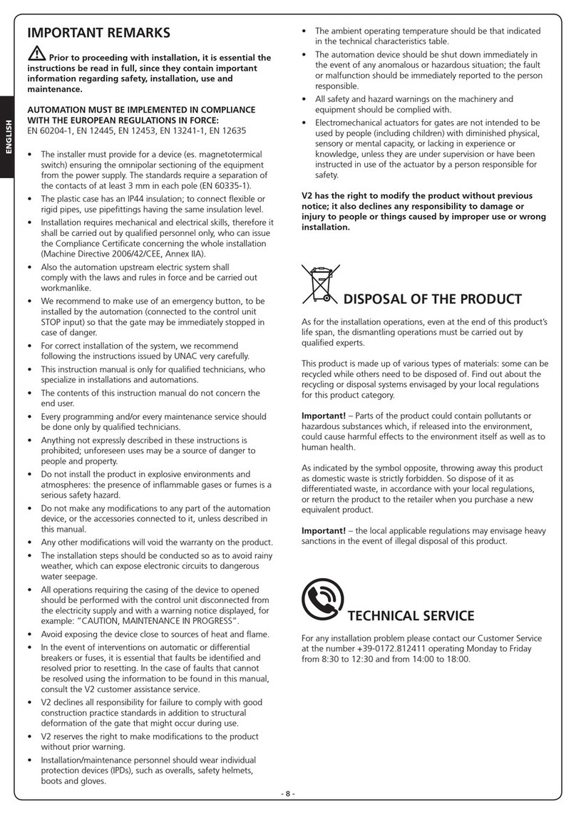
ENGLISH
- 11 -
IMPORTANT REMARKS
mPrior to proceeding with installation, it is essential the
instructions be read in full, since they contain important
information regarding safety, installation, use and
maintenance.
AUTOMATION MUST BE IMPLEMENTED IN COMPLIANCE
WITH THE EUROPEAN REGULATIONS IN FORCE:
EN 60204-1, EN 12453, EN 13241-1, EN 12635
• The installer must provide for a device (es. magnetotermical
switch) ensuring the omnipolar sectioning of the equipment
from the power supply. The standards require a separation of
the contacts of at least 3 mm in each pole (EN 60335-1).
• The plastic case has an IP44 insulation; to connect flexible or
rigid pipes, use pipefittings having the same insulation level.
• Installation requires mechanical and electrical skills, therefore it
shall be carried out by qualified personnel only, who can issue
the Compliance Certificate concerning the whole installation
(Machine Directive 2006/42/CEE, Annex IIA).
• Also the automation upstream electric system shall
comply with the laws and rules in force and be carried out
workmanlike.
• We recommend to make use of an emergency button, to be
installed by the automation (connected to the control unit
STOP input) so that the gate may be immediately stopped in
case of danger.
• For correct installation of the system, we recommend
following the instructions issued by UNAC very carefully.
• This instruction manual is only for qualified technicians, who
specialize in installations and automations.
• The contents of this instruction manual do not concern the
end user.
• Every programming and/or every maintenance service should
be done only by qualified technicians.
• Anything not expressly described in these instructions is
prohibited; unforeseen uses may be a source of danger to
people and property.
• Do not install the product in explosive environments and
atmospheres: the presence of inflammable gases or fumes is a
serious safety hazard.
• Do not make any modifications to any part of the automation
device, or the accessories connected to it, unless described in
this manual.
• Any other modifications will void the warranty on the product.
• The installation steps should be conducted so as to avoid rainy
weather, which can expose electronic circuits to dangerous
water seepage.
• All operations requiring the casing of the device to opened
should be performed with the control unit disconnected from
the electricity supply and with a warning notice displayed, for
example: ”CAUTION, MAINTENANCE IN PROGRESS”.
• Avoid exposing the device close to sources of heat and flame.
• In the event of interventions on automatic or differential
breakers or fuses, it is essential that faults be identified and
resolved prior to resetting. In the case of faults that cannot
be resolved using the information to be found in this manual,
consult the V2 customer assistance service.
• V2 declines all responsibility for failure to comply with good
construction practice standards in addition to structural
deformation of the gate that might occur during use.
• V2 reserves the right to make modifications to the product
without prior warning.
• Installation/maintenance personnel should wear individual
protection devices (IPDs), such as overalls, safety helmets,
boots and gloves.
• The ambient operating temperature should be that indicated
in the technical characteristics table.
• The automation device should be shut down immediately in
the event of any anomalous or hazardous situation; the fault
or malfunction should be immediately reported to the person
responsible.
• All safety and hazard warnings on the machinery and
equipment should be complied with.
• Electromechanical actuators for gates are not intended to be
used by people (including children) with diminished physical,
sensory or mental capacity, or lacking in experience or
knowledge, unless they are under supervision or have been
instructed in use of the actuator by a person responsible for
safety.
V2 has the right to modify the product without previous
notice; it also declines any responsibility to damage or
injury to people or things caused by improper use or wrong
installation.
DISPOSAL OF THE PRODUCT
As for the installation operations, even at the end of this product’s
life span, the dismantling operations must be carried out by
qualified experts.
This product is made up of various types of materials: some can be
recycled while others need to be disposed of. Find out about the
recycling or disposal systems envisaged by your local regulations
for this product category.
Important! – Parts of the product could contain pollutants or
hazardous substances which, if released into the environment,
could cause harmful effects to the environment itself as well as to
human health.
As indicated by the symbol opposite, throwing away this product
as domestic waste is strictly forbidden. So dispose of it as
differentiated waste, in accordance with your local regulations,
or return the product to the retailer when you purchase a new
equivalent product.
Important! – the local applicable regulations may envisage heavy
sanctions in the event of illegal disposal of this product.
TECHNICAL SERVICE
For any installation problem please contact our Customer Service
at the number +39-0172.812411 operating Monday to Friday
from 8:30 to 12:30 and from 14:00 to 18:00.

ENGLISH
- 12 -
PRELIMINARY CHECKS AND IDENTIFICATION OF THE TYPE TO BE USED
It should be remembered that the device does not compensate for defects caused by improper installation, or poor maintenance, thus, prior
to proceeding with installation, ensure that the structure is suitable and meets current standards and, if necessary, perform any structural
modifications aimed at the implementation of safety gaps and the protection or segregation of all crushing, shearing and transit zones, and
verify that:
• Your gate is equipped with a central latch.
• The gate has no friction points, either during closing or opening.
• The gate is well balanced, i.e. there is no tendency to move spontaneously when stopped in any position.
• The position identified for fixing the motor reducer allows easy and safe manual manoeuvring, compatible with the
size of the motor reducer itself.
• The support on which the automation device will be fixed is solid and durable.
• The mains power supply to which the automation device is connected has a dedicated safety earthing system and differential breaker
with tripping current less than or equal to 30 mA (the breaker gap distance should be greater than or equal to 3 mm).
Warning: The minimum safety level depends on the type of use; please refer to the following outline:
GROUP 1 - Only a limited number of people are authorised for use, and closure is not in a public area. Examples of this type are gates inside
business premises, where the sole users are employees, or a part of them who have been suitably informed.
GROUP 2 - Only a limited number of people are authorised for use, but in this case, closure is in a public area. An example of this may be a
company gate that accesses onto a public street, and which is only used by employees.
GROUP 3 - Anyone can use the automated closure, which is thus located on public land. For example the access gate to a supermarket or
an office, or a hospital.
PROTECTION A - Closure is activated by means of a control button with the person present, i.e. with maintained action.
PROTECTION B - With the person present, closure is activated by a command controlled by means of a key-switch or the like, in order to
prevent use by unauthorised persons.
PROTECTION C - Restricts the force of the leaf of the door or gate. I.e., in the case of the gate striking an obstacle, the impact force must
fall within a curve established by the regulations.
PROTECTION D - Devices, such as photocells, capable of detecting the presence of people or obstacles. They may be active on just one side
or on both sides of the door or gate.
PROTECTION E - Sensitive devices, such as footboards or immaterial barriers, capable of detecting the presence of a person, and installed in
such a way that the latter cannot be struck in any way by a moving leaf or panel. These devices should be active within the entire “danger
zone” of the gate. The Machinery Directive defines “Danger Zone” as any zone surrounding and/or near machinery where the presence of
an exposed person constitutes a risk to the health and safety of that person.
The risk analysis should take into consideration all danger zones for the automation device, which should be appropriately
protected and marked.
In a clearly visible area, apply a sign with information identifying the motorised door or gate.
The installer should provide the user with all the information relating to automatic operation, emergency opening and
maintenance of the motorised door or gate.
CLOSURE USE TYPE
TYPE OF ACTIVATION
COMMANDS
GROUP 1
Informed people
(use in private area)
GROUP 2
Informed people
(use in public area)
GROUP 3
Informed people
(unlimited use)
Man-present command A B Not possible
Remote control and closure in
view (e.g. infrared)
C or E C or E C and D or E
Remote control and closure not
in view (e.g. radio)
C or E C and D or E C and D or E
Automatic control
(e.g. timed closure control)
C and D or E C and D or E C and D or E

ENGLISH
- 13 -
EU DECLARATION OF CONFORMITY
AND DECLARATION OF
INCORPORATION OF PARTLY
COMPLETED MACHINE
Declaration in accordance with Directives: 2014/35/UE (LVD);
2014/30/UE (EMC); 2006/42/CE (MD) ANNEX II, PART B
The manufacturer V2 S.p.A., headquarters in Corso Principi di
Piemonte 65, 12035, Racconigi (CN), Italy
Under its sole responsibility hereby declares that:
the partly completed machinery model(s):
STARK6-24V, STARK6-230V
Description: electromechanical actuator for gates
• is intended to be installed on gates, to create a machine
according to the provisions of the Directive 2006/42/EC.
The machinery must not be put into service until the final
machinery into which it has to be incorporated has been
declared in conformity with the provisions of the Directive
2006/42/EC and 89/106/CE.
• is compliant with the applicable essential safety requirements
of the following Directives:
Machinery Directive 2006/42/EC (annex I, chapter 1)
Low Voltage Directive 2014/35/EU
Electromagnetic Compatibility Directive 2014/30/EU
Directive ROHS2 2011/65/CE
The relevant technical documentation is available at the national
authorities’ request after justifiable request to:
V2 S.p.A., Corso Principi di Piemonte 65, 12035, Racconigi (CN),
Italia
The person empowered to draw up the declaration and to provide
the technical documentation:
Sergio Biancheri
Legal representative of V2 S.p.A.
Racconigi 01/06/2019
USE LIMITATIONS
Before installing the product, check
that the sizes and the weight of the
gate leaf are within the limits stated in
CHART 1.
kg - maximum gate leaf weight
m - maximum gate leaf length
mWARNING
• Leaves exceeding 5 metres
should not be panelled.
• Solenoid latch required for 4 m
and above.
• Over 5 m, mechanical stops on
the ground are required. 0 1000
100
200
300
400
kg
500
600
700
800
2000 3000 4000
m
5000 6000 7000
0 1000
100
200
300
400
kg
500
600
700
800
2000 3000 4000
m
5000 6000 7000
STARK6-24V
STARK6-230V
CHART 1

ENGLISH
- 14 -
TECHNICAL DATADESCRIPTION OF THE PRODUCT
This product has been designed to automate gates or
doors with leaf opening, for residential or industrial use.
mCAUTION!
Any other use different to that described and in ambient
conditions different to those set out in this manual is to be
considered improper and forbidden!
The product is an electromechanical gear motor, equipped
with motor and an endless screw reduction gear.
The gear motor is powered by the external control unit to
which it is connected.
In the event of a black out, it is possible to move the gate
leaves by hand, unblocking the gear motor manually.
Fig. 1 shows all the components provided in the package:
a-electromechanical gear motor
b - front bracket and plate (for fixing the gear motor to
the gate leaf)
c - rear bracket and plate (for fixing the gear motor to the
wall)
d - metal parts (screws, washers, etc.)
e-keys to manually unlock the gear motor
a
d
e
b
c
FIG.1
STARK6-24V STARK6-230V
Max. leaf lenght m 6 6
Max. leaf weight Kg 750 750
Power supply Vdc 24 230
Idling current A 0,8 1
Full load current A 7 1,2
Electric power W 170W 240W
Opening time of the leaf 0÷90° s 28 25
Max travel mm 540 540
Operating speed (unloaded) m/s 0,016 0,016
Operating speed (full load) m/s 0,012 0,014
Maximum thrust N 2400 2000
Working temperature °C -20 ÷ +55 -20 ÷ +55
Protection IP 44 44
Working cycle % 80 30
Motor weight Kg 9 10

ENGLISH
- 15 -
INSTALLATION LAYOUT
1 1D
E
3
A
C
2
56
4
A
B
C
D
E
1
2
3
4
5
6
Key switch
Pillar photocells
Pillar-mounted digital radio switch
Safety edges
ECO-LOGIC system (only with STARK6-24V and CITY2+)
Motor
Control unit
Transmitter
Receiving module
Photocells
Flashing light
COMPONENTS ADDITIONAL ACCESSORIES
LENGTH OF THE CABLE < 10 metres from 10 to 20 metres from 20 to 30 metres
Power supply (230V) 3G x 1,5 mm23G x 1,5 mm23G x 2,5 mm2
24V motor power supply 2G x 1,5 mm22G x 1,5 mm22G x 2,5 mm2
Photocells (TX) 2 x 0,5 mm22 x 0,5 mm22 x 0,5 mm2
Photocells (RX) 4 x 0,5 mm24 x 0,5 mm24 x 0,5 mm2
Key switch 2 x 0,5 mm22 x 0,5 mm22 x 0,5 mm2
Safety edges 2 x 0,5 mm22 x 0,5 mm22 x 0,5 mm2
Flashing light 2 x 1,5 mm22 x 1,5 mm22 x 1,5 mm2
Antenna (integrated into the flashing light) RG174 RG174 RG174
ECO-LOGIC (accumulator unit) 2 x 1,5 mm2- -
ECO-LOGIC (solar panel) 2 x 1 mm2- -

ENGLISH
- 16 -
INSTALLATION MEASURES
To carry out a proper installation of the operator parts as well as
to ensure the best automation performance, the measurement
levels shown in the following table shall be complied with.
Change the gate structure to adapt it to one of the cases in the
table, if necessary.
CAUTION: Failure to comply with the bracket installation
distances may lead to automation operation faults, such as:
- Cyclical movements and accelerations at some positions
of the stroke.
- Increased motor noise.
- Limited opening, or no opening at all (in case of
counterlever fixed motor).
A
E
D (945mm)
gE [mm] A [mm]
90°
80 125
90 130
100 150
110 160
120 160
130 165
140 170
150 165
160 170
170 180
180 180
190 180
200 175
210 175
220 170
gE [mm] A [mm]
220 170
230 155
240 150
250 160
260 150
270 145
280 140
290 135
300 135
310 125
320 125
330 120
340 115

ENGLISH
- 17 -
Before it can be fixed to the wall, the bracket must be welded to
the fastening plate (Fig. 3); the bracket may be cut to the desired
length, adjusting distances Aand Eaccordingly
NOTE - The bracket supplied with the gearmotor is 180 mm
long
mWARNING! Before fixing the rear bracket, make sure
that the front bracket will be fixed to a solid position of
the gate leaf; the front bracket will have to be secured at a
different height than the rear bracket (Fig. 4).
28 mm
Fix the bracket in place using suitable plugs, screws and washers
(not supplied)
INSTALLATION OF THE FRONT FIXING
BRACKET
1. For the installation of the front bracket to the gate leaf, refer
to distance D(fig. 2).
2. Define the front bracket installation height in accordance with
fig. 4.
3. Fix the bracket to the solid section of the gate leaf.
FIG.3
FIG.4
gE [mm] A [mm]
100°
80 140
90 150
100 155
110 155
120 170
130 180
140 190
150 195
160 195
170 190
180 190
190 180
200 180
210 180
220 175
230 170
240 170
250 165
260 160
270 160
280 160
290 160
300 160
gE [mm] A [mm]
110°
90 160
100 170
110 180
120 195
130 200
140 200
150 195
160 195
170 195
180 195
190 190
200 190
210 190
220 185
230 185
240 185
250 190

ENGLISH
- 18 -
SECURING THE GEARMOTOR TO THE
FIXING BRACKETS
1. Secure the gearmotor to the rear bracket:
NOTE: if the rear bracket is not completely level, the
back tilting section can help compensate for any axis
misalignments between the two brackets (+/-5°).
- 5°
+ 5°
2. Secure the gearmotor to the bracket as shown in fig. 6, using
the screw, washer and nut supplied;
3. Fully tighten the nut and then loosen it again by approximately
1/10 of a turn, to allow a minimum clearance between the
parts.
1
2
4. Secure the gearmotor to the front bracket.
5. Secure the gearmotor to the bracket as shown in fig. 7, using
the screw and the washer supplied.
6. Fully tighten the screw.
1
2
3
FIG.5
FIG.6
FIG.7
Other manuals for STARK6
1
This manual suits for next models
4
Table of contents
Languages:
Other V2 Controllers manuals
Popular Controllers manuals by other brands

Swagelok
Swagelok KFB Series Maintenance instructions

Danfoss
Danfoss ERC 112D VSC user guide

Siegenia
Siegenia Drive Connect Box Installation and operating instructions

Beam Labs
Beam Labs Pixelator Plus product manual

KIPI
KIPI ecoMAX860P3-C Installation and operating manual

Salus
Salus PCSol 201 Installation and operation manual