VeEX MTT-14B User manual


WARNING
U
s
i
n
g
the
s
u
pp
li
e
d
e
q
u
i
p
m
e
n
t
i
n
a
manner
not
s
p
ec
i
fi
e
d
by
VeEX Inc.
m
a
y
impair the
protection provided
by the
equipment.
CAUTIONS!
•
Do not remove or insert the module while the test set is on. Inserting
or
removing a module with the power on may damage the module.
•
Do not remove or insert the software cartridge while the test set is on. Oth
-
erwise, damage could occur to the
cartridge.
End of Life Recycling and Disposal Information
DO NOT dispose of Waste Electrical and Electronic Equipment
(WEEE)
as
unsorted municipal waste. For proper disposal return the product to VeEX
Inc.
. Please contact
our local offices or
service centers
for information
on
how
to arrange the return and recycling of any of our
products.
Phone: +1 510 651 0500
E-mail: [email protected]
Website: www.veexinc.com
EC
Directive
on
Waste Electrical and Electronic Equipment
(WEEE)
The Waste Electrical and Electronic Equipment Directive aims to minimize the
impact of the disposal of electrical and electronic equipment on the
environment. It encourages and sets criteria for the collection, treatment,
recycling, recovery, and disposal of waste electrical and electronic equipment.
© 2015 VeEX Inc. All rights reserved.
This
device uses software
either
developed
by
VeEX
or
licensed
by
VeEX
from third
parties.
The
software
is
confidential
and
proprietary.
The
software is
protected
by
copyright
and
contains
trade
secrets
of
VeEX
or
VeEX’s
licen
-
sors. The purchaser of this device agrees that it has received a license solely
to
use
the
s
o
f
t
w
a
r
e
as embedded
i
n
the
d
e
v
i
ce
,
and the
purchaser
i
s
p
r
o
h
i
b
i
t
e
d
f
r
o
m
copying, reverse engineering, decompiling,
or
disassembling
the
softwar
e.
MTT-14B e_Manual D07-00-083P RevA00
Page 2 of 101

MTT-14B e_Manual D07-00-083P RevA00
Page 3 of 101

1 SHDSL Module ...................................................................5
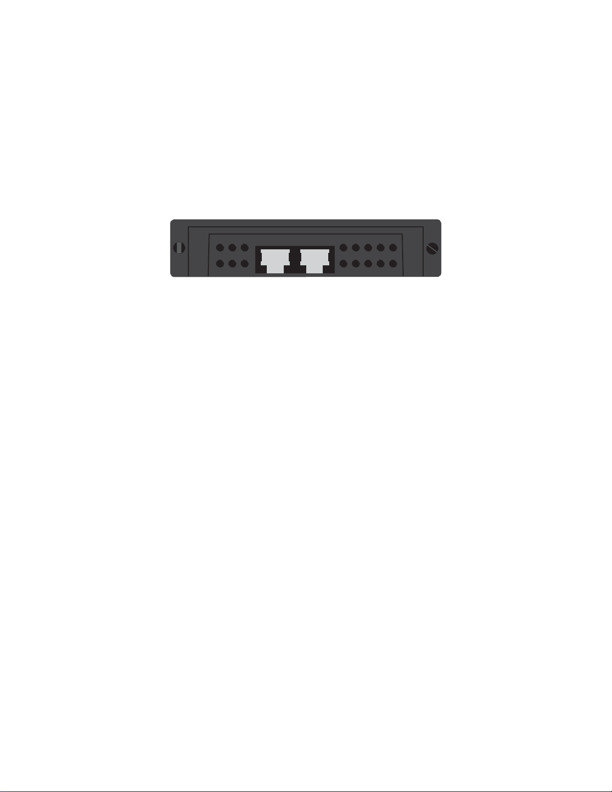
1.1 Connector Panel................................................................5
1.2
LEDs
..................................................................................6
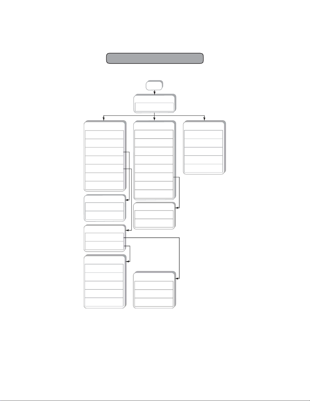
2 SHDSL Menus.....................................................................7
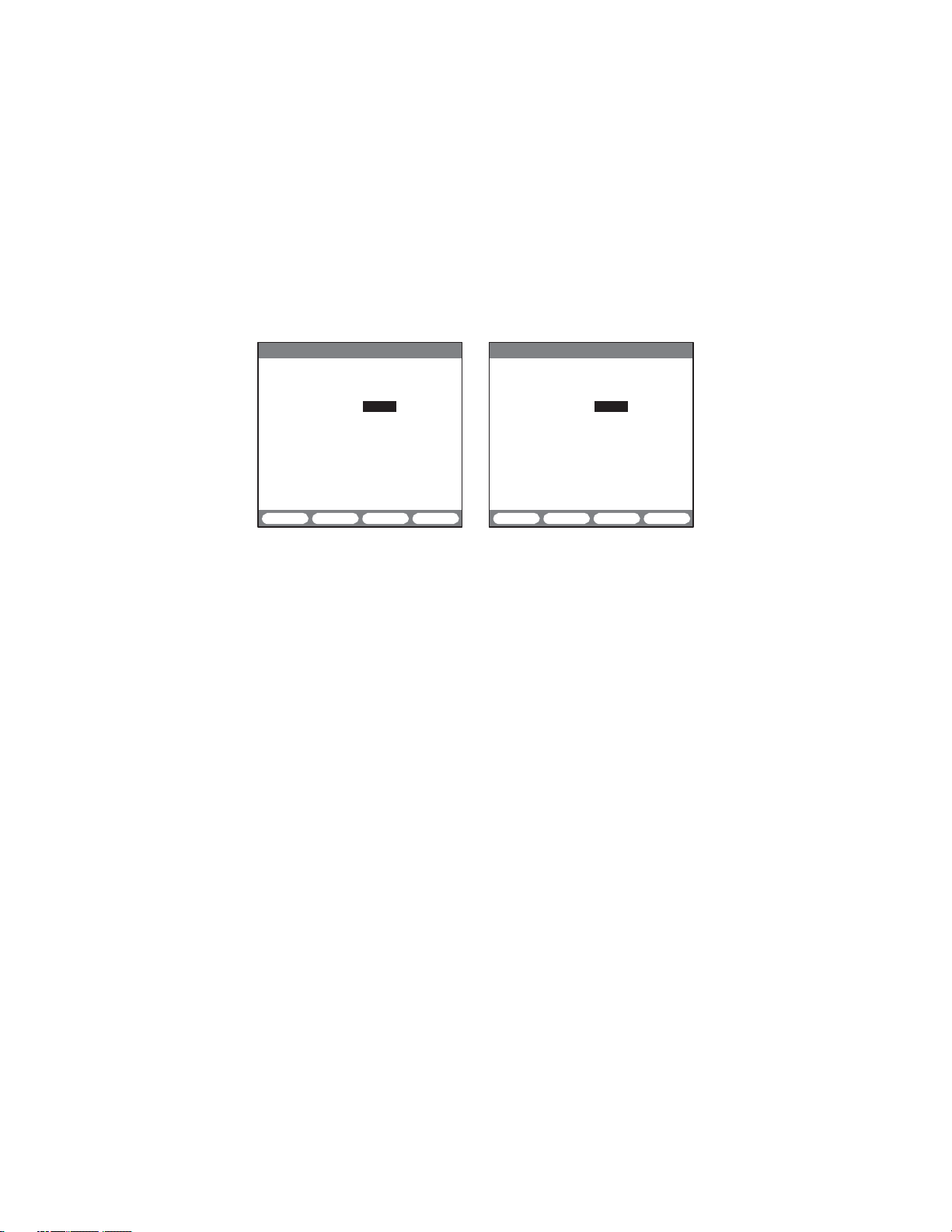
2.1 Test
Configuration
.............................................................8
2.2 STU-C and STU-R
Configuration
......................................8
2.2.1 Modem Status................................................................9
2.2.2 Alarm Status.................................................................11
2.2.3 Modem Control ............................................................12
2.2.3.1
SHDSL
System Loopback
Control ............................12
2.2.3.2 System Settings ........................................................13
2.2.4 PING
Setup/
T
est...........................................................14
2.2.4.1 LLC-Bridge and Routed Mode Setup .......................15
2.2.4.2 CLIPoASetup............................................................17
2.2.4.2.1 LLC-BRG,
LLC-RTE,
and CLIPMode
PING
Results18
2.2.4.3 PPPoA and PPPoEMode Setup...............................20
2.2.4.3.1 Entering a User ID/Password .................................22
2.2.4.3.2 PPPoA and PPPoEMode PING
Results
................23
2.2.4.4
Profile ........................................................................24
2.2.5 Advanced Features......................................................25
2.2.5.1 ATM
Features
............................................................25
2.2.5.1.1 VCC
Scan
...............................................................25
2.2.5.1.2 OAM Cell Generation .............................................29
2.2.5.1.3 OAM Cell Statistics ................................................31
2.2.5.2 IP
Features
................................................................33
2.2.5.2.1
Configuration
..........................................................33
2.2.5.2.2 IP Status.................................................................39
2.2.5.2.3 PING Test ...............................................................43
2.2.5.2.4 Trace
Route
............................................................45
2.2.5.2.5 Echo
Response
......................................................46
2.3 STUC E1, STUR E1, and E1
Configuration
.....................47
2.3.1 Modem Status..............................................................50
2.3.2 Alarm Status.................................................................52
2.3.3 E1 Measurement ..........................................................53
2.3.3.1 Measurement
Definitions
...........................................54
2.3.3.2 E1 Measurement Screens.........................................56
2.3.4 Test Pattern..................................................................59
2.3.4.1 Custom Patterns .......................................................61
2.3.5 Error Injection...............................................................62
2.4 View/Store/Print ..............................................................64
2.4.1 Saving a
Test
................................................................65
2.4.2 Viewing a Stored
T
est...................................................65
MTT-14B e_Manual D07-00-083P RevA00
Page 4 of 101

2.4.3 Printing a Stored
T
est...................................................65
2.4.4 Deleting a Stored
Test
..................................................65
2.4.5 Locking and Unlocking a
Stored
Test ..........................65
2.4.6 Renaming a Stored
T
est...............................................65
2.5
Pr
ofiles
.............................................................................67
3
Applications
......................................................................69
3.1 Loop
Prequalification
......................................................69
3.2 STU-R Emulation-ISP Service.........................................69
3.3 STU-R
Emulation-Private
Network
Service
.....................70
3.4 STU-C Emulation.............................................................70
3.5 Accept a New E1 Circuit .................................................71
3.6 In-Service E1 Circuit Monitoring .....................................72
3.7 Measuring E1 Signal
Level
..............................................73
3.8 V.54
Channel Loopback
Test ...........................................74
3.9 Nx64 kbit/s
T
esting
..........................................................75
4 Reference..........................................................................77
4.1 PING
T
echnology.............................................................77
4.1.1 Classical IP over ATM (CLIPoA)....................................78
4.1.2 Ethernet Frames over ATM
(EoA)
.................................78
4.1.3 PPP over Ethernet
(PPPoE)
over ATM..........................79
4.1.4 PPP over ATM (PPPoA)...............................................79
4.1.5 PING Acronyms............................................................80
4.2 E1 Technology
Overview
.................................................81
4.2.1 Technical Standar
ds
.....................................................81
4.2.2 Basic
Definitions
...........................................................81
4.2.3 Converting a Voice Signal............................................81
4.2.4 2.048 Mbit/s Data Rate ................................................82
4.2.5 Line Coding ..................................................................83
4.2.6 Signal Levels................................................................84
4.2.7 2.048 Mbit/s Framing ...................................................85
5 General Information ........................................................91
5.1 Testing and
CalibrationStatement
..................................91
5.2 Express Limited Warranty...............................................91
Index
.......................................................................................93
MTT-14B e_Manual D07-00-083P RevA00
Page 5 of 101

The SHDSL
module provides
SHDSL
modem emulation.
Mo
d
e
m
emulation includes STU-R, STU-C, STUC E1, STUR E1,
a
n
d
E1
emulation
to verify link
turn-up,
read
performance
data, and
system loopbacks
for
tr
oubleshooting.
1.1 Connector Panel
PAYLOAD STU
Figure 1 Connector
Panel
Themodule panel contains:
PAYLOAD
:
RJ-45 port for E1
testing.
STU: RJ-45 port (for SHDSL testing) Pin out for the STU
port:
pair one is 4 and 5, pair two is 7 and 8.
MTT-14B e_Manual D07-00-083P RevA00
Page 6 of 101

1.2 LEDs
SSMTT-ACM, -ACM+, -EX SSMTT-B,
-C
Figure 2 Test Set LED
Panels
The module uses the following test set LEDs:
MODULE
•
Green: Indicates that the test set is using the module.
xTU-C
•
Green:
Indicates
that the
module
is linked up as
STU-C.
•
Blinking Red:
Indicates
that the
module
is
attempting
to link
up.
xTU-R
•
Green:
Indicates
that the
module
is linked up as
STU-R.
•
Blinking Red:
Indicates
that the
module
is
attempting
to link
up.
LP1 SYNC
•
Green: When link is
established
with far end
device.
•
Red: When link is not
established
with far end
device.
ALARM
•
Red: Indicates that the module has detected an alarm.
MTT-14B e_Manual D07-00-083P RevA00
Page 7 of 101

2.3.4
TEST
PATTERN
2.3.3
E1 MEASUREMENT
2.3.5
ERROR
INJECTION
2.4
VIEW/STORE/PRINT
2.5 PROFILES
2.2.5.2.1
CONFIGURATION
2.2.5.2.2
IP STATUS
2.2.5.2.3
PING TEST
2.2.5.2.4
TRACE
ROUTE
2.2.5.2.5
ECHORESPONSE
2 SHDSL Menus
The following figure
shows
the location of major menu
items.
MODULE
KEY
2
2.1
MAIN
MENU
TEST
CONFIGURATION
2.2 STU-C or STU-R 2.3 STUCE1 or STURE1 2.3 E1
TEST
CONFIGURATION
2.2.1
MODEM
ST
ATUS
2.2.2
ALARM
ST
ATUS
2.2.3
MODEM
CONTROL
2.2.4
PING
SETUP/TEST
2.2.5
ADVANCED
FEATURES
2.4
VIEW/STORE/PRINT
2.5
PROFILES
2.2.3
MODEM
CONTROL
2.2.3.1
LOOPBACK
CONTROL
2.2.3.2
SYSTEM SETTINGS
2.2.5
ADVANCED
FEATURES
2.2.5.1
ATM
FEATURES
2.2.5.2
IP
FEATURES
TEST
CONFIGURATION
2.3.1
MODEM STATUS
2.3.2
ALARMSTATUS
2.3.3
E1 MEASUREMENT
2.3.4
TEST
PATTERN
2.3.5
ERROR
INJECTION
2.3.6
MODEM CONTROL
2.4 VIEW/STORE/PRINT
2.5 PROFILES
2.3.6
MODEM CONTROL
2.3.6.1
LOOPBACKCONTROL
2.3.6.2
SYSTEM
SETTINGS
TEST
CONFIGURATION
2.2.5.2
IP FEATURES
2.2.5.1
ATM
FEATURES
2.2.5.1.1
VCC
SCAN
2.2.5.1.2
OAM CELL
GENERA
TION
2.2.5.1.3
OAM CELL
ST
ATISTICS
Figure 3 Module Menu Tr
ee
MTT-14B e_Manual D07-00-083P RevA00
Page 8 of 101

2.1 Test
Configuration
MODE
determines
the
displayed configuration
scr
een:
MODE
Options: STU-C
(F1),
STU-R
(F2),STUC E1 (F3),STUR E1
(
m
o
r
e
,
F1),
E1 (more, F2)
Select
the
proper operating mode
for the circuit to be
tested.
2.2 STU-C and STU-R
Configuration
08:39:57
>LINK DN- Idle 4W
STU-C<
TEST
CONFIGURATION
MODE : STU-C
WIRES : 4-WIRE
PL RATE : 2304K X2
LN RATE : 2312K X2
STANDARD : ANNEX-A
08:39:57
>LINK DN- Idle 4W
STU-R<
TEST
CONFIGURATION
MODE : STU-R
WIRES : 4-WIRE
PL RATE : 2304K X2
LN RATE : 2312K X2
STANDARD : ANNEX-A
STU-C STU-R STUC-E1 more STU-C STU-R STUC-E1 more
Figure
4 STU-x
Configuration
Scr
eens
Configure
the
following:
WIRES
Options: 2-WIRE
(F1),
4-WIRE(F2)
Select
the type of line that the test set
will
be
connected to.
PL RATE (Payload Rate)
Options:
AUTO (F1),
128K
(F2),
192K
(F3),
256K
(
m
o
r
e
,
F
1
)
, 320K
(
m
o
r
e
, F2), 384K
(
m
o
r
e
, F3), 512K
(
m
o
r
e
,
F
1
)
, 768K
(
m
o
r
e
, F2),
1024K
(
m
o
r
e
, F3), 1152K
(
m
o
r
e
,
F
1
)
, 1280K
(
m
o
r
e
, F2), 1536K
(
m
o
r
e
,
F3),
2048K
(
m
o
r
e
,
F
1
)
, 2304K
(
m
o
r
e
, F2)
Manually choose the PayloadRateor press F1to let the test set
automatically select the correct rate.
LN RATE (LineRate)
Options:
AUTO (F1),
136K
(F2),
200K
(F3),
264K
(
m
o
r
e
,
F
1
)
, 328K
(
m
o
r
e
, F2),392K
(
m
o
r
e
, F3),520K
(
m
o
r
e
,
F
1
)
, 776K
(
m
o
r
e
, F2),
1032K
(
m
o
r
e
, F3), 1160K
(
m
o
r
e
,
F
1
)
, 1288K
(
m
o
r
e
, F2), 1544K
(
m
o
r
e
,
F3),
2056K
(
m
o
r
e
,
F
1
)
, 2312K
(
m
o
r
e
, F2)
Manually choose the Line Rate or press F1 to let the test set
automatically select the correct rate.
Notes for Payload and Line Rates:
•
PL Rate
and LN
Rate are related. Line Rate
is
inclusive
of over-
head. The difference
between
the two are 8K. Whenever
one
configuration
is modified, the other one
will
also be
modified.
MTT-14B e_Manual D07-00-083P RevA00
Page 9 of 101

•
For single ended applications, i.e., STU-R emulation
testing
with a DSLAM, use a fixed rate that
matches
the
expected
commercial service rate.
STANDARD (per ITU G.991.2)
Options:
ANNEX-A (F1),
ANNEX-B(F2)
Select an operating standar
d.
•
ANNEX-A:
Describes specifications
for G.SHDSL
systems
operating
under North American network
conditions.
•
ANNEX-B:
Describes specifications
for G.SHDSL
systems
operating
under
European
network
conditions.
Press ESCto return to the main menu.
2.2.1 Modem Status
Use
these screens
to view real time link
parameters.
Pr
ess
to view the available
scr
eens.
08:39:57
>LINK UP 4W STU-R<
MODEM STATUS
ET: 000:05:54
LINE RATE :1544 kbps X 2
PAYLOAD RATE:1536 kbps X 2
CH1 - STU-C STU-R
CUR SNR MARGIN: 18 dB 16 dB
ATTENUATION : 1 dB 1 dB
CH2 -
CUR SNR MARGIN: 18 dB 16 dB
ATTENUATION : 1 dB 1 dB
PRINT STORE RESET
RETRAIN
Modem Status screens
provide generalperformance
information on the STU-C
and STU-R. For the far end
data, “N/A” is displayed.
Note that CH2 status screen
information is only available
in 4-wire
mode.
08:39:57
>LINK UP 4W STU-R<
MODEM STATUS
ET: 000:05:54
RETRAINS: 0
CH1 - STU-C STU-R
MAX SNR MARGIN : 19 dB 18 dB
MIN SNR MARGIN : 16 dB 13 dB
CRC ERRORS : N/A 0
ERROR SEC : N/A 0
SEVERE ERR SEC : N/A 0
UNAVAILABLE SEC: N/A 0
LOSW SEC : N/A 0
PRINT STORE RESET
RETRAIN
08:39:57
>LINK UP 4W STU-R<
MODEM STATUS
ET: 000:05:54
RETRAINS: 0
CH2 - STU-C STU-R
MAX SNR MARGIN : 19 dB 18 dB
MIN SNR MARGIN : 16 dB 13 dB
CRC ERRORS : N/A 0
ERROR SEC : N/A 0
SEVERE ERR SEC : N/A 0
UNAVAILABLE SEC: N/A 0
LOSW SEC : N/A 0
PRINT STORE RESET RETRAIN
Figure 5 Modem Status Screens
ET: Elapsed Time since
RESET
(F3),
RETRAIN
(F4),or ESC is
pr
essed.
LINE
RATE
reported
in
kbps,
see Section 2.2-Notes for Payload
and Line Rates.
PAYLOAD RATE
reported
in
kbps,
see Section 2.2-Notes
for
Payloadand Line Rates.
MTT-14B e_Manual D07-00-083P RevA00
Page 10 of 101

CUR SNR MARGIN: Current signal-to-noise margin (in dB) is
the maximum dB increase in equalized noise or the maximum
dB decrease in equalized signal that a system can tolerate and
maintain a BER of 10
-7
.
ATTENUATION: This displays the loop attenuation (in dB).
MAX SNR MARGIN: Maximum signal-to-noise margin (in dB)
measured during ET. When either RETRAIN
(F4)
or ESC is
pressed, MAX SNR is reset.
MIN SNR MARGIN: Minimum signal-to-noise margin
(
in
d
B
)
that is measured during ET. When either
RETRAIN (F4)
or ESC
is pressed, MIN SNR is reset.
CRC ERRORS: Count of CRC errors and is reset when ET is
reset.
ERROR SEC: Count of 1 second intervals during which one
or
more
CRC
errors
are
declared and/or one or more
LOSW
d
e
f
e
c
t
s
are declared. Reset when ETis reset.
SEVERE
ERR SEC: Count of 1 second intervals during which
at
least 50 CRCerrors aredeclared or 1 or more
LOSW
defects are
declared. 50 CRC errors during a 1 second interval is equivalent
to a 30% error frame rate for a normal frame length. Reset when
ETis reset.
UNAVAILABLE
SEC: Count of 1 second intervals for which the
SHDSL
li
n
e
i
s
un
a
v
a
il
a
b
l
e
.
The SHDSL
li
n
e
becomes
un
a
v
a
il
a
b
l
e
at the onset of 10 contiguous
SESs. The
10
SESs are
included in
the
un
a
v
a
il
a
b
l
e
t
i
m
e
.
Once
un
a
v
a
il
a
b
l
e
,
the SHDSL
li
n
e
b
ec
o
m
e
s
available at the
onset
of 10
contiguous seconds
with no
SESs.
The 10
seconds
w
i
t
h
no SES are
e
x
c
l
u
d
e
d
from
un
a
v
a
il
a
b
l
e
t
i
m
e
.
Reset when ETis reset.
LOSW SEC: Loss of synchronization word second is a
count
of 1 second intervals during which one or more SHDSL LOSW
defects are declared. Reset when ETis reset.
The following F-keys are
common
to
these
screens:
PRINT
(F1):
Send the status screens to the serial
port.
STORE
(F2):
Press to store the status screen.
RESTART
(F3):
Restarts polling and resets ETto zero.
RETRAIN
(F4):
Retrainsthe modem and resets ETto zero.
MTT-14B e_Manual D07-00-083P RevA00
Page 11 of 101

08:39:57
>LINK UP 4W STU-
R<
ALARM STATUS
LOCAL
REMOTE
curr hist curr
hist
CH1 -
SNR : NO NO NO NO
LOSW: NO NO NO NO
ATTN: NO NO NO NO
CH2 -
SNR : NO NO NO NO
LOSW: NO NO NO NO
ATTN: NO NO NO NO
PRINT STORE
2.2.2 Alarm Status
This screen
pr
ovides
generalalarm
status
(current and history
for
local and remote).
Note CH2 is r
eported
only in 4-wire
mode.
Figure 6 Alarm Status Screen
This screen reports the
following:
SNR:
T
r
i
gg
e
r
e
d
when the
l
o
ca
l
current
SNR
m
a
r
g
i
n
v
a
l
u
e
i
s
b
e
l
o
w
the user threshold setting. This is set in MODEM CONTROL
>
SYSTEM SETTINGS,
on the SNR MARGIN
THRESHOLD
line.
LOSW
:
Loss of Sync defect
alarm,
a loss of synchronization
wo
r
d
defect is declared when at least 3 consecutive received frames
contain 1 or more errors. An LOSW defect is cleared when
at
least 2 consecutive received frames contain no errors.
ATTN: Triggered when the local attenuation value is greater than
the user threshold value. This is set in MODEM CONTROL
>
SYSTEM SETTINGS,
on the LOOP ATTN
THRESHOLD
line.
These alarm conditions are displayed as current and his
t
o
ry.
These
are
defined
as:
curr YES: Thealarm condition is currently
detected.
curr NO: Thealarm condition is not currently
detected.
hist YES: The alarm
condition
has
been detected,
but it is
no
longer
pr
esent.
histNO: The alarm
condition
has never
been detected
since
the
start of the test or since pressing HISTORY.
The following F-keys are
available:
PRINT
(F3):
Send the alarm screen to the serial
port.
STORE
(F4):
Press to store the status screen.
MTT-14B e_Manual D07-00-083P RevA00
Page 12 of 101

2.2.3 Modem Control
This menu contains the
following:
•
LOOPBACKCONTROL
•
SYSTEM
SETTINGS
2.2.3.1 SHDSL System Loopback Control
08:39:57
>LINK UP 4W STU-R<
SHDSL SYSTEM LOOPBACK
STU-C STU-R
T
R
COMMAND :
STATUS :
LOOP-DN STU-C C STU-R N
Figure 7 SHDSL System Loopback Screen
T
h
i
s
screen
d
i
s
p
l
a
y
s
a
l
oo
pb
ac
k
g
r
a
p
h
i
c
.
I
t
i
n
c
l
u
d
e
s
a COMMAND
line
used
to enter different
types
of
loopbackmessages
sent
via
the EOC.They are:
LOOP-DN
(F1):
This will cause the COMMAND line to change
to
LOOP-DN and the
appropriate
EOC
message
will be
sent. The
STATUS
line will report either
SUCCESS
or FAIL.
STU-C C (F2): Use this to
loopback
the STU-C, facing the
cus
-
tomer. This will cause the COMMAND line to change to STU-C
C and the
appropriate
EOC
message
will be
sent.
The
ST
A
TUS
line will report either
WAITING, FAILED, SUCCESS,
or ILLEGAL
ACTION.
STU-R N (F3): Use this to
loopback
the STU-R, facing the
net
-
work. This will
cause
the COMMAND line to
change
to
STU-R
N and the
appropriate
EOC
message
will be
sent.
The
ST
A
TUS
line will report either
WAITING, FAILED, SUCCESS,
or ILLEGAL
ACTION.
MTT-14B e_Manual D07-00-083P RevA00
Page 13 of 101

2.2.3.2 System Settings
Use this screen to adjust the defaults
for:
DISPLAY ALL EOC MESSAGES
•
ON: will display far end values for CRC, SES, ES, UAS, and
LOSW
(if
available). At this time, the
module does
not
support
this
mode.
•
OFF:
is the default.
SNR MARGIN THRESHOLD
Adjust by using +1 (F1) or -1 (F2). The
threshold
can be OFF,
or
adjusted between
-15
through
+15 dB.
If
the SNR margin is
less
than this
setting,
then the
ALARM
LED
will
be
on.
LOOP ATTEN THRESHOLD
Adjust by using +1 (F1) or -1 (F2). The
threshold
can be OFF,
or
adjusted from 1–127. The default setting is
OFF.
If this setting is
exceeded,
then the
ALARM
LED
will
be
on.
RECEIVEEOC SNR OFFSET
For reporting via the EOC(for STU-C/R only).
•
ON: for far end sending SNR raw values to near end.
•
OFF:
for farendsending
SNR
margin
values
to
near
end.OFF
is the default.
SEND EOC SNR OFFSET
For reporting via the EOC(for STU-C/R only).
•
ON: for near end sending SNR margin values to far end. ON
is the default.
•
OFF:
for near end sending SNR raw values to far end.
TRANSFORMER RATIO
•
ON: the transformer ratio is set to 5:4:1. ON is the default.
•
OFF:
the transformer ratio is set to 4:1.
CAUTION:
If
the
reported
loop
attenuation
is significantly dif
fer
-
ent
between
the STU-R and STU-C,
ensure
that the
transformer
ratio used is the same.
When finished
press
ENTER to
update
and save the
changes.
MTT-14B e_Manual D07-00-083P RevA00
Page 14 of 101

2.2.4 PING
Setup/
Test
L
i
n
k
turn-up v
e
r
i
fi
e
s
c
o
nn
ec
t
i
v
i
t
y to a
DSLAM.
P
I
N
G
t
e
s
t
i
n
g
t
a
k
e
s
the
turn-up procedure
one
step
further and verifies
connectivity
to the far end
network.
PING is a
common method
to
discover
whether two remote LAN segments using TCP-IP protocol are
connected. When receiving a PING message, Internet devices
acknowledge
it by
sending
an
echo message back.
After
t
u
r
n
i
n
g
up the
li
n
k
,
enter
P
I
N
G
SETUP/TEST from the
m
o
d
-
ule main menu. The first
screen contains configuration
items
for
the PING test. Enter the
proper protocol used
by the circuit,
as
well as the
necessary
IP
addresses.
The first
setting
is MODE.
Notes:
•
Before
performing
a PING test, confirm that the link is
estab
-
lished.
•
To enter
numbers,press
SHIFT and use the numeric
keypad.
If
available,
use <-,-> to move the
cursor
.
MODE
Options: PROFILE
(F1),
LLC-BRG
(F2),
LLC-RTE
(
m
o
r
e
,
F
1
)
,
CLIPoA (more,
F2),
PPPoE(more,
F1),
PPPoA
(F2,
more)
Select the protocol mode for the PING
test.
•
PROFILE: Use to store and retrieve PING
configurations,
see
Section 2.2.4.4.
•
LLC-BRG:
LL
C
-
B
r
i
d
g
e
p
r
o
t
o
c
o
l
.
T
h
i
s
f
o
ll
o
w
s
RFC 1483
b
r
i
d
g
e
encapsulation.
It
supports
both static and
dynamic
IP
man
-
agement.
•
LLC-RTE: LLC-Routed protocol. It supports only static IP
addr
essing.
•
CLIPoA: This refers to Classical IP over ATM according
to
RFC2225. Used only in
STATIC
mode.
•
PPPoE:
PPPover Ethernet,according to standard
RFC
2516
PPPover Ethernet.
PPPoE
supports dynamic IP addressing.
•
PPPoA: PPP
over
ATM, according
to
standard RFC 2364,
PPP
over AAL5. PPPoA
supports
dynamic
IPaddressing.
The
actual configuration settings depend
on the
selected mode,
hence
the
f
o
ll
o
w
i
n
g
s
u
b
s
ec
t
i
o
n
s
d
e
s
c
r
i
b
e
setup
and
P
I
N
G
r
e
s
u
l
t
s
for each
mode.
MTT-14B e_Manual D07-00-083P RevA00
Page 15 of 101

2.2.4.1 LLC-Bridge and Routed Mode Setup
11:50:50
>LINK UP 4W STU-R<
PING SETUP
MODE :LLC-BRG
ENCAPSULATION :LLC
VPI
:8
VCI
:35
IP ADDRESS
:STATIC
LOCAL IP :207.181.199.178
DESTINATION IP:207.181.199.177
GATEWAY :207.181.199.177
PROFILE LLC-BRG START more
LLC-RTE CLIPoA START more
PPPoE
PPPoA
START more
Figure 8 LLC-BRG PING Setup Screen
Configure
these
s
e
tt
i
n
g
s
for LLC-BRG and LLC-RTE
m
o
d
e
s
:
ENCAPSULATION
Options: LLC
(F1),
VCMUX
(F2),
AUTO(F3)
Choose
the
e
n
ca
p
s
u
l
a
t
i
o
n
method
for
ca
rry
i
n
g
traffic over AAL
Type 5 over ATM.
•
LLC:
L
og
i
ca
l
L
i
n
k
C
o
n
t
r
o
l
based
on
I
EEE
standard
802.2. LLC
encapsulation is used when multiple protocol are
e
n
c
a
p
su
-
lated over a single ATM Virtual C
o
nn
e
c
t
i
o
n.
•
VC
MUX: This is used when only one protocol is carried over
a single ATM Virtual C
o
nn
e
c
t
i
o
n.
•
AUTO:Automatically detect the s
e
tt
in
g
.
VPI
Range:0 through 255
The default is 8, which is a typical Ethernet assignment.
A
l
o
n
g
w
i
t
h
VCI,
V
P
I
i
d
e
n
t
i
fi
e
s
the next
d
e
s
t
i
n
a
t
i
o
n
of a
ce
ll
as
i
t
m
o
v
e
s
through a series of ATM switches on the way to its
d
e
s
t
in
a
t
i
o
n.
The service provider typically assigns VPI.
MTT-14B e_Manual D07-00-083P RevA00
Page 16 of 101

VCI
Range:0 through 65535
The default is 35, which is a typical Ethernet assignment. Along
with VPI,
VCI
identifies the next
destination
of a cell as it
moves
through a series of ATM switches on the way to its destination.
Theservice provider typically assigns VCI.
IP ADDRESS
Options:
STATIC (F1),
DHCP (F2)
•
STATIC:
This type of
IP
management meansthat the user has
a
permanent
IP
address.
For STATIC, enter
the
LOCAL IP;
this
will
be the value
used
during the
test.
•
DHCP: This refers to dynamic IP management. If selected,
enter the IP address for the destination.
D
y
n
a
m
i
c
management
p
r
o
v
i
d
e
s
a way for
computers
to
o
b
t
a
i
n
protocol configuration parameters
(like the local IP
address)
dynamically from the
network.
In this
case,
the IP
address is
not permanent to the terminal; instead, the terminal requests
an
address
from the server on the
network.
When
selecting
DYNAMIC for IP
ADDRESS,
the module sends a request
to
the server; the server responds and provides an IP
addr
ess.
Upon selecting
DYNAMIC,
the
LOCAL IP
line disappears; the
network dynamically
assigns
an IP
addr
ess.
LOCAL IP
Enter a local IP address of the circuit under test. For LLC-BRG
static mode and LLC-RTE, this is the local IP address us
e
d
.
For LLC-BRG DHCP mode, there is no LOCAL IP mode since a
dynamically assigned local IP address is used.
DESTINATION IP
Enter the
destination address
of the
device
to be
pinged.
If
ping
-
ing a gateway, enter the gateway’s address for the Destination
I
P
.
Pinging the
gateway
verifies
connectivity
to the
IS
P
.
GATEWAY
If required, enter a gateway address. A gateway is a device
that
connects
dissimilar
networks
and
passes
information
between
them. In TCP/IP, the default gateway address is the
a
dd
r
e
ss
where the Internet
Protocolsends packets destined
for r
emote
networks, unless
a different route is
configured.
Since LLC-RTE
is a pure routed mode, there is no gateway setting. This
setting
applies only to LLC-BRG
mode.
MTT-14B e_Manual D07-00-083P RevA00
Page 17 of 101

2.2.4.2 CLIPoA Setup
11:50:50
>LINK UP 4W STU-R<
PING SETUP
MODE :CLIPoA
ENCAPSULATION :LLC
VPI
:8
VCI
:35
IP ADDRESS :207.181.199.176
LOCAL IP :207.181.199.178
LLC-RTE
CLIPoA
START more
Figure
9 CLIPoA
Configuration
Scr
een
Configuretheses settings
for
Classical
IP over ATM:
ENCAPSULATION
Options: LLC
LLC is the only
encapsulation method available.
VPI
Range:1 to 255
The default is 8, which is a typical Ethernet assignment. Along
with
VCI,
VPI identifies the next
destination
of a cell as it
moves
through a series of ATM switches on the way to its destination.
Theservice provider typically assigns VPI.
VCI
Range:1 to 65535
The default is 35, which is a typical Ethernet assignment. Along
with VPI,
VCI
identifies the next
destination
of a cell as it
moves
through a series of ATM switches on the way to its destination.
Theservice provider typically assigns VCI.
LOCAL IP
Enter the Local IP
address
of the circuit to be
tested.
DESTINATION IP
Enter the
Destination
IP
address
to be
pinged.
MTT-14B e_Manual D07-00-083P RevA00
Page 18 of 101

2.2.4.2.1
LLC-BRG, LLC-RTE,
and CLIP Mode PING Results
After
c
o
n
fi
g
u
r
i
n
g
,
press
F3 to
start
the
test.
A
s
the
testp
r
o
cee
d
s
,
the test set displays an ‘IN
PROGRESS’
message.
•
The
module will send 10
PINGs
at one-second intervals.One
or more responses from the destination is considered a pass.
Refer to the following figure for a
pass sample.
12:30:55
>LINK UP 4W STU-R<
ST:12:30:10 ET:00:00:45
LOCAL IP:207.181.199.178
DEST IP :207.181.199.177
PING
TEST
PING :
PASS
PING STOP
Figure 10 LLC PING Test
Passed
•
‘PING PASS’ means the destination has received the PING
m
e
ss
a
g
e
a
n
d
properly responded to
t
h
e
module.
T
hisin
d
i
c
a
t
e
s
that the module can connect to the Internet.
•
Ifthe test set
receives
noresponse,it will display ‘PINGFAIL’.
This indicates that either the destination did not receive the
PINGmessage or it did not reply.
•
Press F4 to stop the test, press it again to restart
testing.
•
Press F1 to PING the DEST IP again after PING: PASS is
displayed.
In addition to the test results, the screen also r
eports:
ET: Elapsed Time since the test was started or restarted.
ST: Start Time of the
test.
LOCAL IP: Provides the local IP address for the module. For
LLC-BRG static and
LLC-RTE,
this is the exact
LOCAL IP a
dd
r
e
ss
entered
i
n
the
c
o
n
fi
g
u
r
a
t
i
o
n
screen.
For LLC-BRG DHCP, LOCAL
IP shows all zeros until the DHCP server assigns an IP
addr
ess.
When assigned, the LOCAL IP line will display this
addr
ess.
DEST IP: Provides the destination IPaddress for the
PING mes
-
sages.
This is
determined
in the
configuration
scr
een.
MTT-14B e_Manual D07-00-083P RevA00
Page 19 of 101

If selecting LLC-BRG, DHCP IP ADDRESS, the PING r
e
sul
t
s
screen
d
i
ff
e
r
s
s
li
g
h
t
l
y from
F
i
g
u
r
e
10. For DHCP, the network
m
u
s
t
assign the local IP address. Thereare two steps for the results:
1. When the test first begins, the
LOCAL
IP
address
line shows all
zeros.As soon as the
DHCP server
provides an IP address,
it
updates
and DHCP displays ‘PASS’ as in the following figure:
12:30:55
>LINK UP 4W STU-R<
ST:12:30:10 ET:00:00:45
LOCAL
IP:001.002.003.004
DEST IP
:002.003.004.005
PING
TEST
DHCP : PASS
PING :
IN PROGRESS
STOP
Figure 11 DHCP: IP AddressAssigned
2. After r
ece
i
v
i
n
g
an
I
P
address,
the
test set
b
e
g
i
n
s
t
r
a
n
s
m
i
tt
i
n
g
PING messages using the local IP address. When a reply is
r
ece
i
v
e
d
,
‘
P
I
N
G
P
A
SS
’
i
s
d
i
s
p
l
a
y
e
d
as
i
n
the
f
o
ll
o
w
i
n
g
fi
g
u
r
e
:
12:30:55
>LINK UP 4W STU-R<
ST:12:30:10 ET:00:00:45
LOCAL
IP:001.002.003.004
DEST IP
:002.003.004.005
PING
TEST
DHCP :
PASS
PING :
PASS
START
Figure 12 DHCP: PING Passed
MTT-14B e_Manual D07-00-083P RevA00
Page 20 of 101
This manual suits for next models
1
Table of contents
Other VeEX Test Equipment manuals

VeEX
VeEX MTX150x Lite User manual

VeEX
VeEX Fiber Scope Inspector User manual

VeEX
VeEX VePAL TX300 User manual

VeEX
VeEX NET-BOX User manual

VeEX
VeEX VePAL BX100A Series Guide

VeEX
VeEX V-SAM VePAL V300 User manual

VeEX
VeEX LX100 Guide

VeEX
VeEX FX120 User manual

VeEX
VeEX DS3 BERT User manual

VeEX
VeEX MPX100 User manual

VeEX
VeEX FL41 User manual

VeEX
VeEX RXT-1200 User manual

VeEX
VeEX VePAL TX300M User manual

VeEX
VeEX RXT-6200 User manual

VeEX
VeEX MTTplus-420 User manual

VeEX
VeEX MTTplus User manual

VeEX
VeEX CX380C User manual

VeEX
VeEX UX400 User manual

VeEX
VeEX OTDR FX150+ Series User manual

VeEX
VeEX VePAL TX300 User manual