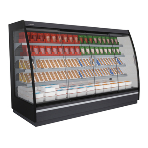
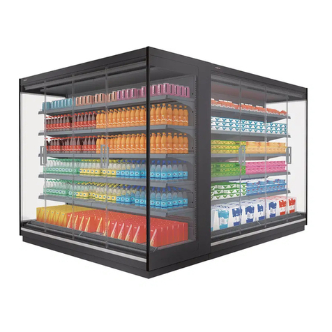
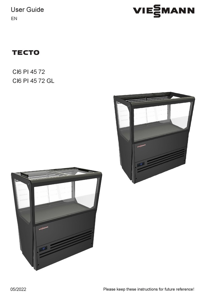
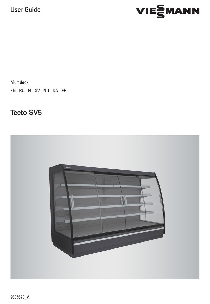
Viessmann Tecto SV5 User manual

Tecto SV5
9606286_0
Installation Guide
Multideck
EN

Original instructions

EN DE ES FR PL RU NL FI SV NO DA EE LT LV
2
Original instructions
1.Introduction......................................................................................................................................................3
1.1.Contents of delivery ...........................................................................................................................3
2.Restrictions and warnings..............................................................................................................................4
3.Preparations.....................................................................................................................................................5
3.1.Required documents ..........................................................................................................................5
3.2.Required tools for multiplexing ........................................................................................................5
3.3.Required equipment for moving cabinets........................................................................................5
4.Unloading and preparing cabinets ................................................................................................................6
4.1.Preparing electrical junction boxes..................................................................................................8
5.Connecting cabinets .......................................................................................................................................9
6.Drainage ...........................................................................................................................................................11
7.Finishing...........................................................................................................................................................12
7.1.Installing bumper trim and corner pieces ........................................................................................12
7.2.Installing plinth plates........................................................................................................................13
7.3.Removing shelf transport braces .....................................................................................................13
CONTENTS

EN DE ES FR PL RU NL FI SV NO DA EE LT LV
3
Read these instructions carefully.
Tecto SV5 cabinets must be installed and started up in compliance with the manufacturer's instructions and
local instructions and regulations.
Note!
Tecto SV5 cabinets are meant for indoor use only.
Normal ambient conditions must not exceed:
Relative humidity 60 % RH
Ambient temperature +25 °C
Frontal airflow < 0.2 m/s
Note!
No part of this document creates any legally binding obligations to Viessmann Refrigeration Systems.
The contents of this document are sub
j
ect to chan
g
e without prior notice.
1.1. Contents of delivery
The delivery contains:
cabinets as specified when placing order
accessory packages as specified when placing order (inside the cabinets)
installation and user manual (one per ordered line of cabinets)
multiplexing kit
Multiplexing kit
DIN 912 / ISO 4762
1 x M8 (40 mm)
3 x M8 (80 mm)
2 x M6 (60 mm)
2 x M6 (100 mm)
DIN 9021/ ISO 7093
4 x M8
2 x M7
2 x M6
DIN 934 / ISO 4032
1 x M6
4 x M8
DIN 7504-K / ISO 15480
24 x (4.8 x 16 mm)
2 x (6.3 x 70)
DIN 933 / ISO 4017
1 x M6 (35 mm)
Plastic guide pins,
2 x
Metal guide pins,
4 x
Exadan expanding insulating tape,
3-15 mm x 18 mm, 1 roll (5 m)
Mapa insulating tape,
4 mm x 10 mm, (1 m)
Canopy brace, 2 x
Rectangular washer (M8), 2 x
M6 nylock nut, 2 x
DIN 522 / ISO 4759-3
4 x M6 (40 mm)
Bolt sleeve, Ø 8 mm
2 x
1. Introduction

EN DE ES FR PL RU NL FI SV NO DA EE LT LV
4
Due to fire hazard, only qualified technicians are allowed to install the system.
No electrical equipment should be placed inside the cabinets unless specifically approved by the
manufacturer.
The cabinets are heavy. Take note of the centre of gravity when lifting.
Handle with care cabinets with glass doors to avoid injuries or damage to the doors.
Cabinet parts may have sharp edges, wear protective gloves during installation.
Do not place cabinets so that they are subject to draft.
Do not place cabinets near a heat source, such as radiators, hot air fans or hot lighting fixtures.
Do not place cabinets in direct sunlight. If necessary, use blinds on any nearby windows.
Note!
Be careful not to damage plumbing fixtures or plinth plate supports on the bottom of the cabinets when lifting.
Never lift cabinets with glass ends from the short end!
Note!
Climbing or standing on the cabinet roof during installation is not allowed.
Note!
If the canopy is equipped with a control unit (optional extra), the cabinet must be handled with special care to
avoid damaging the protruding display.
Note!
When placing the electrical junction box on the cabinet roof, use a protective covering to avoid scratching.
WARNING!
If a defect occurs in the cabinet or cabinet equipment during installation or start-up, or if the cabinet does not
operate normally, make sure that this does not create a hazard to people or property. If necessary, disconnect the
cabinet from the mains and contact the nearest service organisation.
WARNING!
If you suspect a refrigerant leakage, ventilate the premises immediately!
WARNING!
Only licensed professionals are allowed to install refrigerant lines or electrical equipment!
2. Restrictions and warnings

EN DE ES FR PL RU NL FI SV NO DA EE LT LV
5
3.1. Required documents
Make sure you have the following documents:
Layout-drawing of the store
Electrical wiring diagram
Confirmation of order
3.2. Required tools for multiplexing
Make sure you have the following tools:
1 Spirit level
2 Laser level
3 Pipe cutter
4 Ratchet wrench with sockets
5 Drill, electrical screwdriver
6 Wrench, 16mm for adjustable foot
7 Screwdriver and bits
8 Carpet knife
- Lint free tissue or cloth for cleaning
3.3. Required equipment for moving cabinets
Make sure that you have proper equipment for lifting and moving the cabinets.
3. Preparations

EN DE ES FR PL RU NL FI SV NO DA EE LT LV
6
Before you start:
Check the layout drawing for the intended locations of the cabinets.
Measure out and mark the locations of the cabinets on the floor.
Inform customers of any changes to the layout.
Note!
Be careful when lifting and moving cabinets: the cabinets’ centre of gravity may be at an unexpected point.
Use rubber pads between the cabinet chassis and forklift forks or pallet jack.
Remove the transport brackets securing the cabinet
feet to the pallet
(
4 pcs
)
.
Lift the cabinet off the pallet.
Rec
y
cle the pallet and packa
g
in
g
material.
Take the line cabinets to their installation position and push them towards each other.
Note!
Use a pallet jack or castors under the cabinet feet for easier manoeuvring.
Note!
Make sure there is a 135 mm
g
ap between the lower back walls of line cabinets.
4. Unloading and preparing cabinets

EN DE ES FR PL RU NL FI SV NO DA EE LT LV
7
Remove any fibre remains from all cabinet ends and
wipe clean with a damp cloth.
Apply insulating tape on line cabinet ends.
Take the end cabinet to its final installation position.
Do not push the cabinets together yet.
Note!
Use a pallet jack or castors under the cabinet feet
for easier manoeuvring.
Level by adjusting the cabinet feet (6x).
Note!
Adjust the feet at the cabinet ends first.
Adjust feet in the middle last.
In each line cabinet: insert 1 x metal guide pin
and 1 x canopy brace in the canopy profile, and
one plastic guide pin into the base.
Note!
Before pushing the cabinets together, make sure all
electrical junction boxes are properly located!

EN DE ES FR PL RU NL FI SV NO DA EE LT LV
8
4.1. Preparing electrical junction boxes
Junction boxes on the end cabinets are packed on the outside of the cabinet.
Note!
Handle the junction boxes and their cabling carefully to avoid damage to electrical parts!
When assembling an SV5 panorama island, the end cabinets’ junction boxes must be mounted on the back of
the line cabinet to their right. See the following illustration.
Without overhead piping:
The junction boxes of the end cabinets are mounted
on the back of the line cabinets to their right
(cabinets B and D).
A and C = end cabinets
B and D = line cabinets
Red rectangle = electrical junction box
DOC018985_19

EN DE ES FR PL RU NL FI SV NO DA EE LT LV
9
Push the cabinets together. Make sure the guiding
pins and the canopy brace slide into their
corresponding slots on the end cabinet.
Remove the bottom plates at the end of line cabinets.
Connect line cabinet to end cabinet at the base using
a bolt sleeve, bolt (M6 x 100 mm), M6 nut
And Ø 40 mm washers.
Note!
Insert the bolt sleeve from the end cabinet’s side.
Remove the honeycombs at the end of each line
cabinet. Loosen the screws holding the retaining strip
in place. Push the retaining strip back and remove the
honeycomb strip.
5. Connecting cabinets

EN DE ES FR PL RU NL FI SV NO DA EE LT LV
10
Connect line cabinet to end cabinet using screw and
washer. Insert bolt through the angle brackets on the
back of each cabinet.
Insert a bolt through the angle brackets underneath
the canopy and tighten with a nut.

EN DE ES FR PL RU NL FI SV NO DA EE LT LV
11
1. Cut drainage pipes to correct length.
2. Round the pipe ends.
3. Install to fittings.
4. Mount and fasten horizontally to the cabinet bottom.
A: First or last cabinet in a row: use two elbow joints.
B: Between cabinets: use an elbow joint and a T-section.
Adjust the distance between two elbow joints or elbow joint and T-section with a short pipe.
6. Drainage

EN DE ES FR PL RU NL FI SV NO DA EE LT LV
12
7.1. Installing bumper trim and corner pieces
Assemble the plastic bumper trim.
Line up two bumper trim sections and slide the top
notch on one section into the bottom groove on the
other.
Insert the notch on the assembled plastic bumper trim
into the groove on the bottom of the trim profile. Then
press firmly down until the bumper trim locks into
place.
Press the corner piece onto the end of the bumper trim. Do this at both corners of the panorama cabinet.
7. Finishing

EN DE ES FR PL RU NL FI SV NO DA EE LT LV
13
Push the bumper trim plates on the other side onto corner piece. Do this at both corners of the panorama cabinet.
Note!
As the corner glass of a fully assembled and installed SV5 panorama island is exposed and vulnerable to
collisions, it is strongly recommended to use protective 450 mm tall anti-collision posts in front of all corners.
7.2. Installing plinth plates
Mount the plinth plates:
A) Pull down plinth plate supports on cabinet
front. Plinth plate supports on the
panorama cabinet sides are fixed into
position. Secure the supports on the
cabinet front with two screws.
B) Screw plinth plates onto the supports with
two screws for each support.
7.3. Removing shelf transport braces
Bend the top arm of the transport brace upwards with,
for example, a screwdriver and pull the transport
brace out.


02/2022
Copyright Viessmann
Duplication and alternative use only with prior written consent.
Subject to technical modifications.
Austria
Viessmann Kühlsysteme Austria GmbH
Telephone +43 72 35 66367-0
www.viessmann.at
Belgium
Viessmann Nederland B.V.
Telephone +31 10 4584444
www.viessmann.be
Czech Republic
Viessmann, spol. s r.o.
Telephone + 420 257 090 900
www.viessmann.cz
Denmark
Viessmann Refrigeration Systems ApS
Telephone +45 4120 5420
www.viessmann.dk
Estonia
Viessmann Külmasüsteemid OÜ
Telephone +372 675 5150
www.viessmann.ee
Finland
Viessmann Refrigeration Systems Oy
Telephone +358 19 537 8000
info.fi@viessmann.com
www.viessmann.com
Viessmann Kylmäjärjestelmät Oy
Telephone +358 19 537 8000
info.fi@viessmann.com
www.viessmann.fi
France
Viessmann Technique du Froid S.à.r.l.
Telephone +33 3 87 13 08 13
www.viessmann.fr
Germany
Viessmann Kühlsysteme GmbH, Hof
Telephone +49 9281 814-0
Viessmann Kühlsysteme GmbH, Mainz
Telephone +49 61315 7046-17
www.viessmann.de
Ireland
Viessmann Refrigeration Systems Limited
Telephone +353 1 617 7930
sales@viessmann-coldtech.ie
www.viessmann-coldtech.ie
Latvia
Viessmann Refrigeration Systems Latvia
filiále
Telephone +371 6782 8449
www.viessmann.com
Netherlands
Viessmann Nederland B.V.
Telephone +31 10 4584444
www.viessmann.nl
Norway
Viessmann Refrigeration Systems AS
Telephone +47 3336 3500
www.viessmann.no
Poland
Viessmann Systemy Chłodnicze Sp. z o.o.
Telephone +48 22 882 0020
www.viessmann.pl
Russia
Viessmann Refrigeration Systems
Moscow
Telephone +7 499 277 1260
www.viessmann.ru
Slovakia
Viessmann, s.r.o.
Telephone +421 32 23 01 00
www.viessmann.sk
Sweden
Viessmann Refrigeration Systems AB
Telephone +46 8 5941 1200
www.viessmann.se
Switzerland
Viessmann (Schweiz) AG
Telephone +41 56 418 67 11
www.viessmann.ch
United Arab Emirates
Viessmann Middle East FZE
Telephone +971 43724247
www.viessmann.ae
United Kingdom
Viessmann Refrigeration Systems Limited
Telephone +44 1952 457157
sales@viessmann-coldtech.co.uk
www.viessmannrefrigeration.co.uk
Other manuals for Tecto SV5
2
Table of contents
Other Viessmann Commercial Food Equipment manuals
Viessmann
Viessmann Tecto SV5 User manual

Viessmann
Viessmann Tecto SV5 User manual

Viessmann
Viessmann norpe PROMOTER User manual

Viessmann
Viessmann norpe EUROCLASSIC User manual
Viessmann
Viessmann Tecto MD5 User manual

Viessmann
Viessmann TECTO CI6 PI 45 72 User manual

Viessmann
Viessmann GALILEI Tecto CI2 User manual

Viessmann
Viessmann GALILEI Tecto CI4 User manual

Viessmann
Viessmann Norpe SAGA User manual
Viessmann
Viessmann Tecto FL2 Aida User manual