manuals.online logo
Brands
  1. Home
  2. •
  3. Brands
  4. •
  5. VISIONARY DESIGNS
  6. •
  7. Indoor Furnishing
  8. •
  9. VISIONARY DESIGNS VK-1320 Manual

VISIONARY DESIGNS VK-1320 Manual

www.classicexhibits.com
866.652.2100
© 2013
WHEN DISASSEMBLING ALUMINUM EXTRUSION, TIGHTEN ALL
SETSCREWS AND LOCKS TO PREVENT LOSS DURING SHIPPING
Order #XXXXX - 10x10 - VK-1320 Modied - General Layout
Plan View
10’
10’
www.classicexhibits.com
866.652.2100
© 2013
WHEN DISASSEMBLING ALUMINUM EXTRUSION, TIGHTEN ALL
SETSCREWS AND LOCKS TO PREVENT LOSS DURING SHIPPING
Order #XXXXX - General Information
The Tool Typical Connection
Horizontal Inline Connection (remove only one setscrew)
Base Plate Connection Vertical Connection
(remove only two setscrews)
Most Visionary Designs exhibits can be
assembled with the supplied Hex Key Tool.
Occasionally, a flat head screwdriver may
be required.
Most horizontal extrusion connections have a patented expandable lock. This lock inserts into
the groove of an opposing extrusion. Tightening the lock with the Hex Key Tool expands the lock
and creates a strong positive connection.
Remove only (1) setscrew when disassembling. Replace setscrew in
extrusion after assembling it. Before packing, replace setscrew in
extrusion to avoid losing it.
Attach base plate to round or square
vertical extrusion using the bolt provided.
Be careful not to strip the threads.
When vertical extrusions are packed in
portable cases rather than crates or
tubs, they must broken down into
smaller sections which then require
assembly.
Remove only (2) setscrews when
disassembling. Replace setscrews in
extrusion after assembling it. Before
packing, replace setscrews in extrusion
to avoid losing them.
Using Your Setup Instructions
The Visionary Designs Setup Instructions are created specifically for your
configuration. They are laid out sequentially, including an exploded view of
the entire display, and then a logical series of detailed steps to assemble the
main structure and components. We encourage you to study the instructions
before attempting to assemble your exhibit.
Each page reminds you to tighten the setscrews after disassembling your
exhibit to prevent loss of the locks and setscrews (see below in RED).
This is VERY IMPORTANT.
Cleaning and Packing Your Display
1) Use care when cleaning aluminum extrusion or acrylic inserts. Use only
non-abrasive cleaners.
2) When cleaning laminate inserts or countertops, use mild cleansers and a
soft material such as cotton.
3) Keep all display components away from extreme heat and long exposure
to sunlight to avoid warping and fading.
4) Retain all packing material. It will make re-packing much easier and will
reduce the likelihood of shipping damage.
Typical Connection (cont’d)
Numbered Label
Each extrusion contains a numbered label which
corresponds with setup instructions.
The label is located within a groove of the extrusion
(when possible). With Visionary Designs the labels
contain Black numbers unless otherwise specified.
Detail C EliateDDliateDDetail B
Detail A
Setscrews
www.classicexhibits.com
Step 1
866.652.2100
© 2013
WHEN DISASSEMBLING ALUMINUM EXTRUSION, TIGHTEN ALL
SETSCREWS AND LOCKS TO PREVENT LOSS DURING SHIPPING
Order #XXXXX -
Page 1 of 6
Backwall Assembly
When
assembled
Item
1
2
3
4
5
6
7
Qty.
2
1
1
1
1
1
1
Description
Base Plate
47.1239” Curved Extrusion
Curved Leg Assembly
47.1239” Curved Extrusion
Curved Leg Assembly
Steps:
1) Attach base plates [1] to curved leg
assemblies [3,7].
2) Attach curved extrusion [2] between
two leg assemblies [3,7].
3) Attach other curved extrusions
between two leg assemblies [3,7].
1
2
4
5
6
7
3
1
Graphic Attachment
Apply graphic to back
of assembled backwall.
Velcro attached to back
of curved extrusions [2,4,5,6]
for graphic attachment.
www.classicexhibits.com
Step 2
866.652.2100
© 2013
WHEN DISASSEMBLING ALUMINUM EXTRUSION, TIGHTEN ALL
SETSCREWS AND LOCKS TO PREVENT LOSS DURING SHIPPING
Order #XXXXX -
Page 2 of 6
Backwall Assembly (Cont’d)
Steps:
1) Attach wings to assembled round frame
as shown. Refer to A10 clamp detail.
Back
Wing
Back
Wing
Back
Wing
Back
Wing
*
*
*
*
**
*
*
*
Tighten set screw to
secure A10 to extrusion.
A10 Clamp Detail
Tighten knob to secure
header/wing in place.
www.classicexhibits.com
Step 3
866.652.2100
© 2013
WHEN DISASSEMBLING ALUMINUM EXTRUSION, TIGHTEN ALL
SETSCREWS AND LOCKS TO PREVENT LOSS DURING SHIPPING
Order #XXXXX -
Page 3 of 6
Backwall Assembly (Cont’d)
When
assembled
Steps:
1) Attach front wings and round graphic header
to assembled round frame as shown.
Refer to Graphic Attachment detail.
2) Attach a light to top of assembled round frame.
Refer to Light Connection detail.
Back Wings in BLACK
Graphic
Header
Front Wings in BLUE
Graphic
Cap
Standoff
Barrel
Slide connector on back of
standoff barrels into groove of
extrusion and twist to secure in
place. Secure graphic to
standoffs using screw caps.
Graphic Attachment
*
*
*
*
*
Light Connection
Attach lights to
backwall where
desired and
tighten in place.
www.classicexhibits.com
Step 4
866.652.2100
© 2013
WHEN DISASSEMBLING ALUMINUM EXTRUSION, TIGHTEN ALL
SETSCREWS AND LOCKS TO PREVENT LOSS DURING SHIPPING
Order #XXXXX -
Page 4 of 6
VK-1605 - Workstation Assembly
Part Number
A
B
C
D
Steps:
1) Connect lower horizontal extrusion [C] between bottom of leg assemblies [A and B] as shown.
2) Insert Laminated infill into grooves of leg assemblies [A and B].
3) Attach extrusion door between leg assemblies [A and B] and on top of laminated infill.
4) Attach upper horizontal extrusion w/ door stopper [D] between leg assemblies [A and B],
and set flush with top of legs [A and B].
Description
Left Leg Assembly
Right Leg Assembly
Horizontal Extrusion
Horiontal Extrusion w/ Door Stopper
Black
Knob
Turn Knob Clockwise
to Tighten Lock
DOOR
Laminated Infill
A(left)
B(right)
C
D(w/ Door Stopper)
Knobs face INSIDE
of workstation
Knobs face INSIDE
of workstation
Knobs face FORWARD
Pins are
located on INSIDE
FRONT vertical
of Leg
Assemblies
NOTE: Make sure the lock is flush with extrusion before tightening. If lock will not fully
engage, gently rock lock and extrusion back and forth while turning knob until lock
fully opens.
Align with bottom of leg assemblies [A and B].
www.classicexhibits.com
Step 5
866.652.2100
© 2013
WHEN DISASSEMBLING ALUMINUM EXTRUSION, TIGHTEN ALL
SETSCREWS AND LOCKS TO PREVENT LOSS DURING SHIPPING
Order #XXXXX -
Page 5 of 6
VK-1605 - Workstation Assembly (Cont’d)
Part Number
E
F
Steps:
1) Attach horizontal extrusion [E] between vertical leg assemblies [A and B] as shown below.
2) Insert Laminated infill into grooves of vertical leg assemblies [A and B].
3) Attach upper horizontal extrusion [F] between vertical leg assemblies [A and B] on top of infill.
4)
Place internal shelf into assembled pedestal on top of pins.
5) Set Counter on top of assembled pedestal and secure with Velcro straps attached to underside of top.
Description
Horizontal Extrusion
E
Laminated
Infill
Knobs facing FORWARD
Place internal shelf into workstation then place counter on top of
assembled workstation.
Internal
Shelf
F
Knobs face INSIDE
of workstation
www.classicexhibits.com
Step 6
866.652.2100
© 2013
WHEN DISASSEMBLING ALUMINUM EXTRUSION, TIGHTEN ALL
SETSCREWS AND LOCKS TO PREVENT LOSS DURING SHIPPING
Order #XXXXX -
Page 6 of 6
VK-1605 - Workstation Assembly (Cont’d)
Part Number
G
Steps:
1)
Slide Connection Bar into lower leg assembly. Slide upper vertical over bar and secure both.
2) Attach Monitor Mount to vertical as shown in Detail below.
Description
Curved Montior Mount Extrusion
G
Vertical
Connection Bar Slide Connection Bar into lower
leg assembly. Slide upper vertical
over bar and secure both.
V20
Adjust V20 connector to
desired location.
Then remove screws.
Place mount plate
in front of V20 connectors.
Then secure with screws.
NOTE: Monitor mount should be installed
while laying down on floor
Monitor Mount Attachment
www.classicexhibits.com
866.652.2100
© 2013
WHEN DISASSEMBLING ALUMINUM EXTRUSION, TIGHTEN ALL
SETSCREWS AND LOCKS TO PREVENT LOSS DURING SHIPPING
Order #XXXXX - Packing Instructions - Case 1
Additional Items:
Halogen Lights
Graphics
Setup Hardware
6
1 (x2)
Back
Wings
Graphic
Header
Top View of Each Level
Level 1 Level 2 Level 3 Level 4 Level 5
Base Plates
2
5
43
Level 5
7
Front
Wings
www.classicexhibits.com
866.652.2100
© 2013
WHEN DISASSEMBLING ALUMINUM EXTRUSION, TIGHTEN ALL
SETSCREWS AND LOCKS TO PREVENT LOSS DURING SHIPPING
Order #XXXXX - Packing Instructions - Case 2
Level 1 Level 2 Level 3 Level 4 Level 5
Top View of each Level
Counter
Internal
Shelf
Inserts
Door
Leg Assembly
B
Leg Assembly
A
Horiz. Extrusion E
Horiz. Extrusion F
Vertical Extrusion G

Other VISIONARY DESIGNS Indoor Furnishing manuals

VISIONARY DESIGNS MOD-9002 User manual
VISIONARY DESIGNS

VISIONARY DESIGNS MOD-9002 User manual

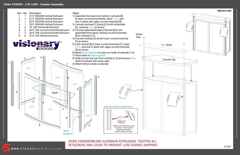
VISIONARY DESIGNS LTK-1109 User manual
VISIONARY DESIGNS

VISIONARY DESIGNS LTK-1109 User manual

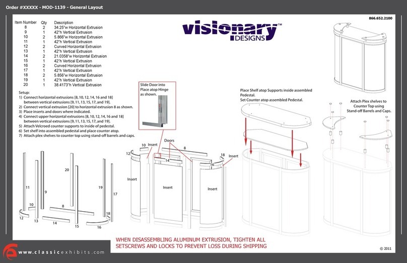
VISIONARY DESIGNS MOD-1139 Manual

VISIONARY DESIGNS

VISIONARY DESIGNS MOD-1139 Manual
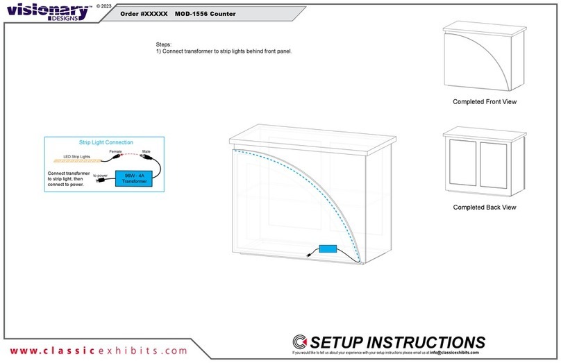
VISIONARY DESIGNS MOD-1556 Manual

VISIONARY DESIGNS

VISIONARY DESIGNS MOD-1556 Manual
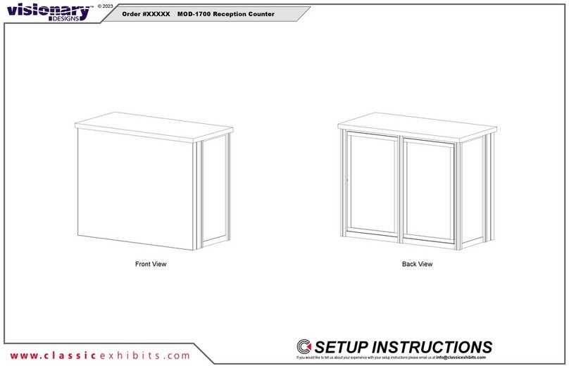
VISIONARY DESIGNS MOD-1700 Manual

VISIONARY DESIGNS

VISIONARY DESIGNS MOD-1700 Manual
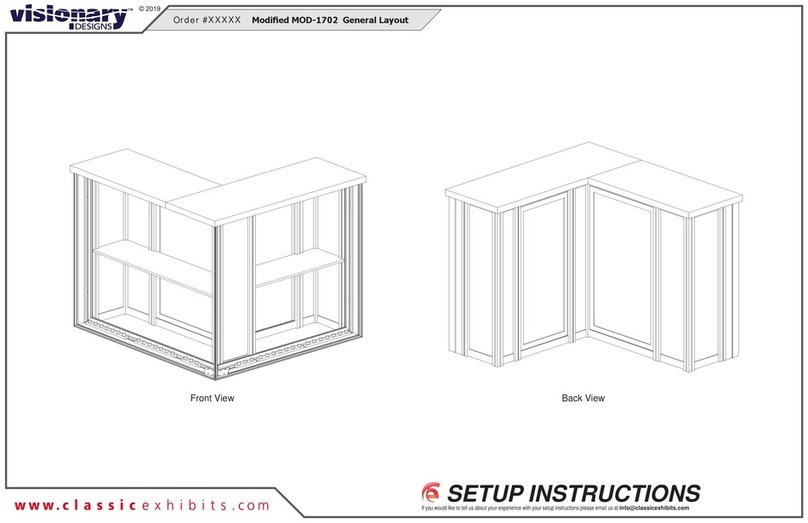
VISIONARY DESIGNS MOD-1702 Manual

VISIONARY DESIGNS

VISIONARY DESIGNS MOD-1702 Manual

VISIONARY DESIGNS Hybrid Inline VK-1100 Manual
VISIONARY DESIGNS

VISIONARY DESIGNS Hybrid Inline VK-1100 Manual

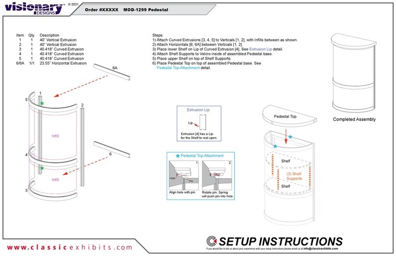
VISIONARY DESIGNS MOD-1299 Manual

VISIONARY DESIGNS

VISIONARY DESIGNS MOD-1299 Manual
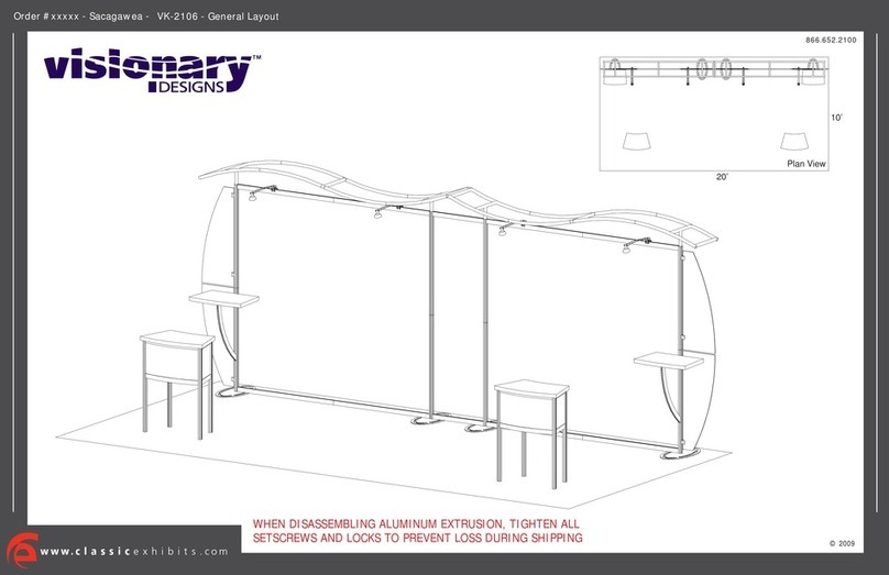
VISIONARY DESIGNS VK-2106 User manual

VISIONARY DESIGNS

VISIONARY DESIGNS VK-2106 User manual

VISIONARY DESIGNS LTK-1115 Manual

VISIONARY DESIGNS

VISIONARY DESIGNS LTK-1115 Manual

VISIONARY DESIGNS VK-2979 Manual

VISIONARY DESIGNS

VISIONARY DESIGNS VK-2979 Manual
VISIONARY DESIGNS MOD-1243 Manual

VISIONARY DESIGNS

VISIONARY DESIGNS MOD-1243 Manual
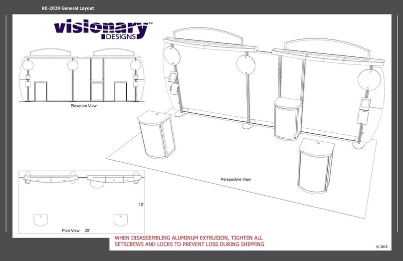
VISIONARY DESIGNS RE-2029 User manual

VISIONARY DESIGNS

VISIONARY DESIGNS RE-2029 User manual
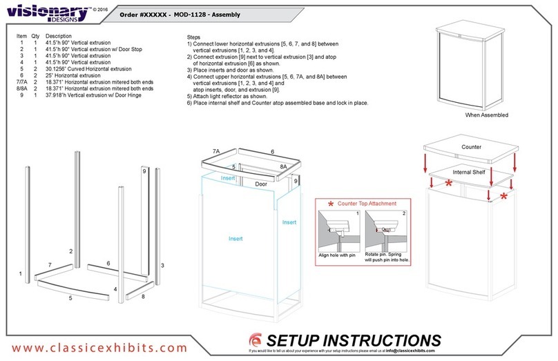
VISIONARY DESIGNS MOD-1128 Manual

VISIONARY DESIGNS

VISIONARY DESIGNS MOD-1128 Manual
VISIONARY DESIGNS VK-1048 Manual

VISIONARY DESIGNS

VISIONARY DESIGNS VK-1048 Manual
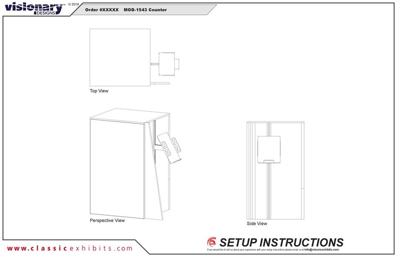
VISIONARY DESIGNS MOD-1543 Manual

VISIONARY DESIGNS

VISIONARY DESIGNS MOD-1543 Manual
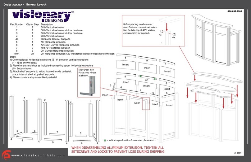
VISIONARY DESIGNS MOD-1143 User manual

VISIONARY DESIGNS

VISIONARY DESIGNS MOD-1143 User manual

VISIONARY DESIGNS VK-5095 User manual

VISIONARY DESIGNS

VISIONARY DESIGNS VK-5095 User manual

VISIONARY DESIGNS MOD-1514 Manual

VISIONARY DESIGNS

VISIONARY DESIGNS MOD-1514 Manual
VISIONARY DESIGNS MOD-1567 User manual

VISIONARY DESIGNS

VISIONARY DESIGNS MOD-1567 User manual

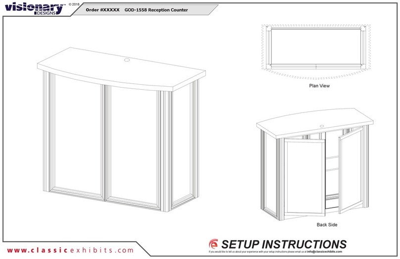
VISIONARY DESIGNS GOD-1558 Manual

VISIONARY DESIGNS

VISIONARY DESIGNS GOD-1558 Manual

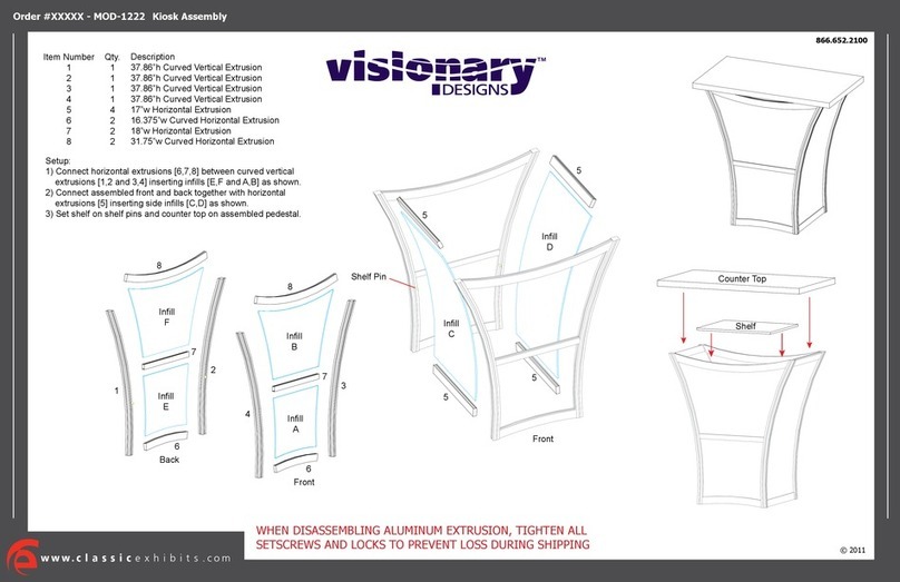
VISIONARY DESIGNS MOD-1222 User manual

VISIONARY DESIGNS

VISIONARY DESIGNS MOD-1222 User manual

VISIONARY DESIGNS VK-1334 Manual

VISIONARY DESIGNS

VISIONARY DESIGNS VK-1334 Manual

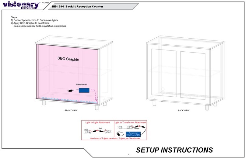
VISIONARY DESIGNS RE-1584 Manual

VISIONARY DESIGNS

VISIONARY DESIGNS RE-1584 Manual

Popular Indoor Furnishing manuals by other brands

Regency LWMS3015 Assembly instructions

Regency

Regency LWMS3015 Assembly instructions

Furniture of America CM7751C Assembly instructions

Furniture of America

Furniture of America CM7751C Assembly instructions

Safavieh Furniture Estella CNS5731 manual

Safavieh Furniture

Safavieh Furniture Estella CNS5731 manual

PLACES OF STYLE Ovalfuss Assembly instruction

PLACES OF STYLE

PLACES OF STYLE Ovalfuss Assembly instruction

Trasman 1138 Bo1 Assembly manual

Trasman

Trasman 1138 Bo1 Assembly manual

Costway JV10856 manual

Costway

Costway JV10856 manual

moss DESIGN Caisson Credenza Assembly instructions

moss DESIGN

moss DESIGN Caisson Credenza Assembly instructions

Aquaglide FULL DECK 15.0 owner's manual

Aquaglide

Aquaglide FULL DECK 15.0 owner's manual

AREBOS AR-HE-SW30 user manual

AREBOS

AREBOS AR-HE-SW30 user manual

Till-Hilft Fulda 87005.330 Assembly instructions

Till-Hilft

Till-Hilft Fulda 87005.330 Assembly instructions

Twoey Outside 2010 quick start guide

Twoey Outside

Twoey Outside 2010 quick start guide

Hettich Easys 200 operating instructions

Hettich

Hettich Easys 200 operating instructions

The bedboss RELAX 404 Series owner's manual

The bedboss

The bedboss RELAX 404 Series owner's manual

Oeseder Möbelindustrie Bern 991 720 Assembly instructions

Oeseder Möbelindustrie

Oeseder Möbelindustrie Bern 991 720 Assembly instructions

Costway HW68469 user manual

Costway

Costway HW68469 user manual

Next ALIX A27743 Assembly instructions

Next

Next ALIX A27743 Assembly instructions

BROSA Hans Assembly guide

BROSA

BROSA Hans Assembly guide

Prodigg MINIKA PBA015T-FUR installation manual

Prodigg

Prodigg MINIKA PBA015T-FUR installation manual

manuals.online logo
manuals.online logoBrands
  • About & Mission
  • Contact us
  • Privacy Policy
  • Terms and Conditions

Copyright 2025 Manuals.Online. All Rights Reserved.