manuals.online logo
Brands
  1. Home
  2. •
  3. Brands
  4. •
  5. VISIONARY DESIGNS
  6. •
  7. Indoor Furnishing
  8. •
  9. VISIONARY DESIGNS VK-2106 User manual

VISIONARY DESIGNS VK-2106 User manual

www.classicexhibits.com
Step 1
Page 1 of 5
866.652.2100
© 2009
WHEN DISASSEMBLING ALUMINUM EXTRUSION, TIGHTEN ALL
SETSCREWS AND LOCKS TO PREVENT LOSS DURING SHIPPING
Order #xxxxx - Sacagawea - VK-2106 - General Layout
10’
20’ Plan View
www.classicexhibits.com
Step 2
Page 2 of 5
866.652.2100
© 2009
WHEN DISASSEMBLING ALUMINUM EXTRUSION, TIGHTEN ALL
SETSCREWS AND LOCKS TO PREVENT LOSS DURING SHIPPING
Order #xxxxx - Sacagawea - General Information
The Tool Typical Connection
Horizontal Inline Connection (remove only one setscrew)
Base Plate Connection Vertical Connection
(remove only two setscrews)
Most Visionary Designs exhibits can be
assembled with the supplied Hex Key Tool.
Occasionally, a flat head screwdriver may
be required.
Most horizontal extrusion connections have a patented expandable lock. This lock inserts into
the groove of an opposing extrusion. Tightening the lock with the Hex Key Tool expands the lock
and creates a strong positive connection.
Remove only (1) setscrew when disassembling. Replace setscrew in
extrusion after assembling it. Before packing, replace setscrew in
extrusion to avoid losing it.
Attach base plate to round or square
vertical extrusion using the bolt provided.
Be careful not to strip the threads.
When vertical extrusions are packed in
portable cases rather than crates or
tubs, they must broken down into
smaller sections which then require
assembly.
Remove only (2) setscrews when
disassembling. Replace setscrews in
extrusion after assembling it. Before
packing, replace setscrews in extrusion
to avoid losing them.
Using Your Setup Instructions
The Visionary Designs Setup Instructions are created specifically for your
configuration. They are laid out sequentially, including an exploded view of
the entire display, and then a logical series of detailed steps to assemble the
main structure and components. We encourage you to study the instructions
before attempting to assemble your exhibit.
Each page reminds you to tighten the setscrews after disassembling your
exhibit to prevent loss of the locks and setscrews (see below in RED).
This is VERY IMPORTANT.
Cleaning and Packing Your Display
1) Use care when cleaning aluminum extrusion or acrylic inserts. Use only
non-abrasive cleaners.
2) When cleaning laminate inserts or countertops, use mild cleansers and a
soft material such as cotton.
3) Keep all display components away from extreme heat and long exposure
to sunlight to avoid warping and fading.
4) Retain all packing material. It will make re-packing much easier and will
reduce the likelihood of shipping damage.
Typical Connection (cont’d)
Numbered Label
Each extrusion contains a numbered label which
corresponds with setup instructions.
The label is located within a groove of the extrusion
(when possible). With Visionary Designs the labels
contain Black numbers unless otherwise specified.
Detail C EliateDDliateDDetail B
Detail A
Setscrews
www.classicexhibits.com
Step 1
Page 1 of 5
866.652.2100
© 2009
WHEN DISASSEMBLING ALUMINUM EXTRUSION, TIGHTEN ALL
SETSCREWS AND LOCKS TO PREVENT LOSS DURING SHIPPING
Order #xxxxx - Sacagawea - Backwall Assembly
Set upper horizontal bars
[51/5b] to be flush with
top of vertical extrusions.
Horizontal Placement
3a
5a
2a
3a
1
4a
1
2
3
5a
4b
5b
Connection
Bar
Slide Connection Bar
between Extrusions
and tighten Knobs
to secure.
Connection
Bar
Graphic Attachment
Apply graphic to back
of assembled backwall.
Connection
Bar
a
a
b
Connection
Bar b
A10 clamps attached to vertical extrusions fo Wing Attachment
Item
1
2
3
2a
3a
4a/4b
5a/5b
Description
Base Plate
42”h Lower Square Vertical Extrusion
42”h Upper Square Vertical Extrusion
42”h Lower Square Vertical Extrusion w/ A10 Clamps Attached
42”h Upper Square Vertical Extrusion w/ A10 Clamps Attached
45”w Horizontal Extrusion
Qty.
2
1
1
1
1
1/1
1/1
Steps:
1) Attach vertical extrusions [2] to base plates [1].
2) Attach upper vertical extrusions [3a and 3] to lower extrusions [2a and 2]
using connection bar [a].
3) Connect horizontal extrusions [4a to 4b and 5a to 5b] together using connection bar [b].
4) Attach horizontal assemblies [4a/4b and 5a/5b] between vertical assemblies as shown.
5) Apply graphic to back of assembled backwall.
6) Attach light to top of assembled backwall.
Turn Knob Clockwise
to Tighten Lock
STAR indicates location of
knobs on BACKSIDE of unit.
**Do not over tighten Knobs.**
Knob
Knob
Light Connection
Attach Lights to
Backwall where
desired and tighten
in place.
GREEN STAR indicates
location of connection
lock with knob.
www.classicexhibits.com
Step 2
Page 2 of 5
866.652.2100
© 2009
WHEN DISASSEMBLING ALUMINUM EXTRUSION, TIGHTEN ALL
SETSCREWS AND LOCKS TO PREVENT LOSS DURING SHIPPING
Order #xxxxx - Sacagawea -
GREEN STAR indicates
location of connection
lock with knob.
Slide Connection Bar
between Extrusions
and tighten Knobs
to secure.
Connection
Bar
Graphic Attachment
Apply graphic to back
of assembled backwall.
Connection
Bar
a
a
b
A10 clamps attached to vertical extrusions fo Wing Attachment
Item
1
4a/4b
5a/5b
7
8
7a
8a
9
10
Description
Base Plate
45”w Horizontal Extrusion
42”h Lower Square Vertical Extrusion
42”h Upper Square Vertical Extrusion
42”h Lower Square Vertical Extrusion w/ A10 Clamps Attached
42”h Upper Square Vertical Extrusion w/ A10 Clamps Attached
24”w Horizontal Extrusion
Qty.
2
1/1
1/1
1
1
1
1
1
1
Steps:
1) Attach vertical extrusions [7 and 7a] to base plates [1].
2) Attach upper vertical extrusions [8 and 8a] to lower extrusions [7 and 7a]
using connection bar [b].
3) Connect horizontal extrusions [4a to 4b and 5a to 5b] together using connection bar [a].
4) Attach horizontal assemblies [4a/4b and 5a/5b] between vertical assemblies as shown.
5) Apply graphic to back of assembled backwall.
6) Attach light to top of assembled backwall.
**Do not over tighten Knobs.**
Knob
Knob
Connection
Bar b
11
77a
4a 4b
5a 5b
9
10
5b
4b
2
3
88a
STAR indicates location of
knobs on BACKSIDE of unit.
Turn Knob Clockwise
to Tighten Lock
Backwall Assembly Cont’d
www.classicexhibits.com
Step 3
Page 3 of 5
866.652.2100
© 2009
WHEN DISASSEMBLING ALUMINUM EXTRUSION, TIGHTEN ALL
SETSCREWS AND LOCKS TO PREVENT LOSS DURING SHIPPING
Order #xxxxx - Sacagawea -
Item
14
15
15a
Description
30.2” Curved Extrusion
12.184”w Horizontal Extrusion
Flange Plate
Qty.
2
2
2
Steps:
1) Connect horizontal extrusion [15] to curved extrusion [14].
2) attach assembled counter support [14/15] to vertical where indicated.
3) Attach flange plate [15a] to top of curved extrusion [14] as shown.
4) Attach counter atop support, see counter top attachment detail.
5) Repeat steps for additional counter.
6) Attach monitor mounts to assembled backwall, see attachment details below.
7) Attach wigns to A10 clamps.
Counter Top Attachment
Insert screws located on underside
of counter into holes on flange plate
and secure with wing nuts.
Wing Nut
Monitor Mount Attachment
V4 Connectors
Attach monitor mount back plate
to connectors using screws provided.
Slide A10 Clamp
into groove
of square extrusion.
When desired location
is found, tighten
set screw to secure.
Set-
Screw
A10
Tighten black plastic
set screw to secure
Wing in place.
Black Plastic
Set-screw
Wing Attachment
*Note: A10 clamps must
stay attached with verticals
*
*
*Note: Curved extrusion
[14] and horizontal [15]
must stay assembled
when shipping.
Screw
15a
14
15
Screw
15a
14
15
*
Counter and Wing Attachment
www.classicexhibits.com
Step 4
Page 4 of 5
866.652.2100
© 2009
WHEN DISASSEMBLING ALUMINUM EXTRUSION, TIGHTEN ALL
SETSCREWS AND LOCKS TO PREVENT LOSS DURING SHIPPING
Order #xxxxx - Sacagawea -
Connections are made by holding the button
down and sliding the red tube into opposing
tube until the connection is made. To disassemble
push button and pull or twist extrusions apart.
Push-Button
Push-Button
66
6
6
Numbered Label
Using Your Setup Instructions
The Aero Overhead Sign Setup Instructions are created specifically for your configuration. They include an
exploded view of the frame which is sequentially numbered. We encourage you to study the instructions
before attempting to assemble your exhibit.
Connections are kept very simple: no tools. Everything assembles with push-button
connectors and pre-connected horizontal sections.
Cleaning and Packing Your Display
1) Use care when cleaning aluminum extrusion or acrylic inserts. Use only non-abrasive cleaners.
2) Retain all packing material. It will make re-packing much easier and will reduce the likelihood
of shipping damage.
Serpentine Canopy Assembly
Steps:
1) Connect canopy pieces together as shown.
2) Apply pillow case graphic to assembled canopy
AA
BB
D
D
CC
Push-Button
Push button then rotate
for packing purposes
E
F
E
FG
H
G
H
www.classicexhibits.com
Step 5
Page 5 of 5
866.652.2100
© 2009
WHEN DISASSEMBLING ALUMINUM EXTRUSION, TIGHTEN ALL
SETSCREWS AND LOCKS TO PREVENT LOSS DURING SHIPPING
Order #xxxxx - Sacagawea -
Part Number
16
17/17a
18
Qty
4
2/2
2
Description
38”h Vertical Extrusion
12”w Horizontal Extrusion
25”w Horizontal Extrusion
Steps
1)
Attach horizontal extrusions [17 and 17a] between vertical
extrusions [16], placing inserts between horizontals.
2) Attach curved horizontal extrusions [18] between
vertical extrusions [116], placing insert between
curved horizontals.
Sintra Insert
Top View
16
17
Shelf
Steps (Cont’d):
3) Place shelf atop lip of extrusions.
4) Set counter top atop assembled base.
Counter
Extrusions 17a
have a lip for the
floor to rest
upon.
Lip for Shelf
Placement
Lip
Extrusion Details:
16
17a
17
18
18
16
16 16
17a
17
16
17
16 16
*Note: Pedestal sides
must stay assembled
when shipping
Pedestal Assembly - QTY. 2
www.classicexhibits.com
866.652.2100
© 2009
WHEN DISASSEMBLING ALUMINUM EXTRUSION, TIGHTEN ALL
SETSCREWS AND LOCKS TO PREVENT LOSS DURING SHIPPING
Order #xxxxx - Case Packing Instruction - Case 1 of 4
(1) Backwall Components
Extrusions #3&3a
Extrusions #2&2a
Horizontal extrusions #4a&4b abd 5a&5b
Connection Bars A
Connection Bars B
Counter
Top
Base Plates
Backwall Counter
Support
Level 1 Level 2 Level 3
Wing Panels
Canopy
Slip Sheet
Setup Hardware
and Graphics
Halogen LightHalogen Light
www.classicexhibits.com
866.652.2100
© 2009
WHEN DISASSEMBLING ALUMINUM EXTRUSION, TIGHTEN ALL
SETSCREWS AND LOCKS TO PREVENT LOSS DURING SHIPPING
Order #xxxxx - Case Packing Instruction - Case 2 of 4
Extrusions #7&7a
Extrusions #8&8a
Horizontal extrusions #4a&4b abd 5a&5b
Connection Bars A
Connection Bars B
Counter
Top
Base Plates
Backwall Counter
Support
Level 1 Level 2 Level 3
Wing Panels
Canopy
Slip Sheet
Setup Hardware
and Graphics
Halogen LightHalogen Light
(2) Backwall Components
www.classicexhibits.com
866.652.2100
© 2009
WHEN DISASSEMBLING ALUMINUM EXTRUSION, TIGHTEN ALL
SETSCREWS AND LOCKS TO PREVENT LOSS DURING SHIPPING
Order #xxxxx -
Level 1 Level 2 Level 3 Level 4
Counter Top
Curved Extrusions # 18
Assembled
Pedestal
Side
Assembled
Pedestal
Side
Front Insert
Internal Shelf
(3) Pedestal Components
Case Packing Instruction - Case 3 of 4
www.classicexhibits.com
866.652.2100
© 2009
WHEN DISASSEMBLING ALUMINUM EXTRUSION, TIGHTEN ALL
SETSCREWS AND LOCKS TO PREVENT LOSS DURING SHIPPING
Order #xxxxx -
Level 1 Level 2 Level 3 Level 4
Counter Top
Curved Extrusions # 18
Assembled
Pedestal
Side
Assembled
Pedestal
Side
Front Insert
Internal Shelf
(4) Pedestal Components
Case Packing Instruction - Case 4 of 4

Other VISIONARY DESIGNS Indoor Furnishing manuals

VISIONARY DESIGNS MOD-1701c Manual

VISIONARY DESIGNS

VISIONARY DESIGNS MOD-1701c Manual

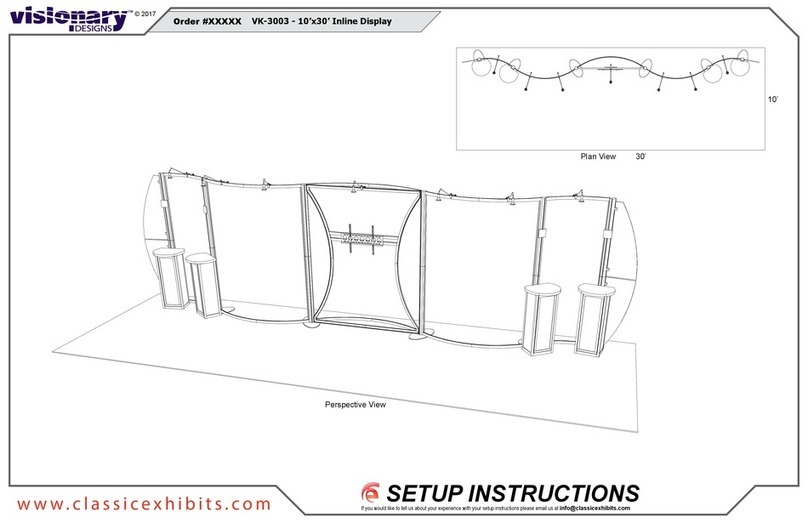
VISIONARY DESIGNS VK-3003 Manual

VISIONARY DESIGNS

VISIONARY DESIGNS VK-3003 Manual

VISIONARY DESIGNS VK-5095 User manual

VISIONARY DESIGNS

VISIONARY DESIGNS VK-5095 User manual

VISIONARY DESIGNS MOD-9002 User manual

VISIONARY DESIGNS

VISIONARY DESIGNS MOD-9002 User manual

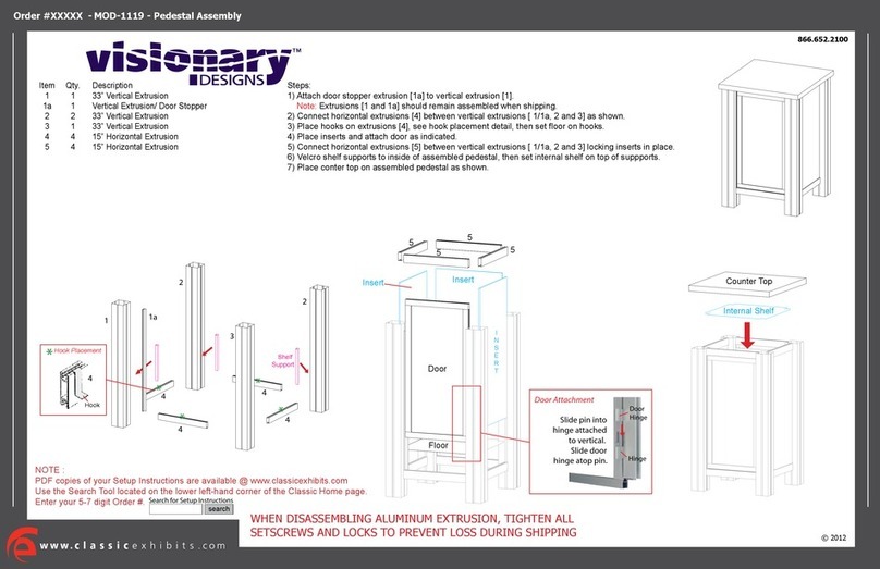
VISIONARY DESIGNS MOD-1119 User manual

VISIONARY DESIGNS

VISIONARY DESIGNS MOD-1119 User manual

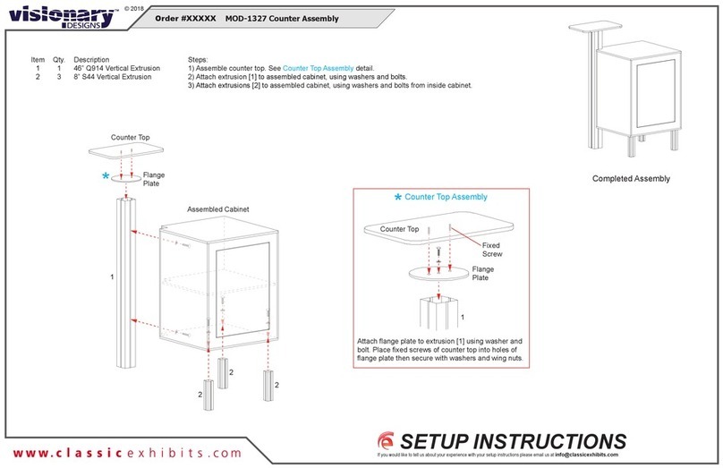
VISIONARY DESIGNS MOD-1327 User manual

VISIONARY DESIGNS

VISIONARY DESIGNS MOD-1327 User manual

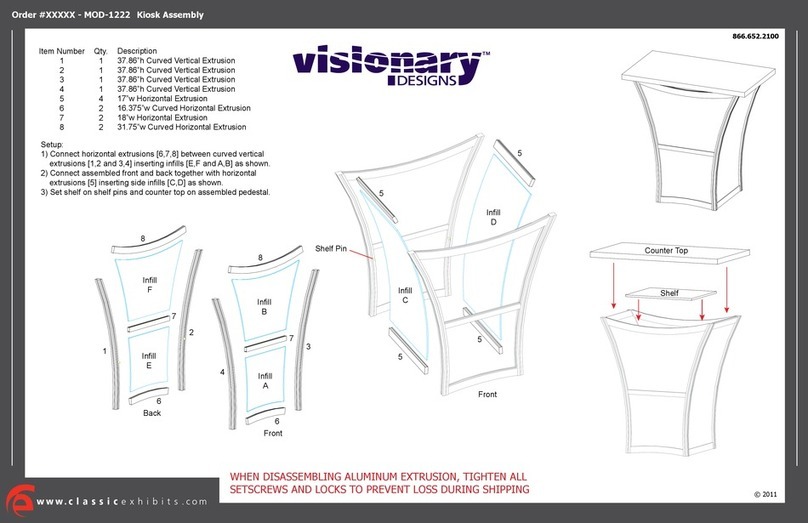
VISIONARY DESIGNS MOD-1222 User manual

VISIONARY DESIGNS

VISIONARY DESIGNS MOD-1222 User manual

VISIONARY DESIGNS VK-1048 Manual

VISIONARY DESIGNS

VISIONARY DESIGNS VK-1048 Manual

VISIONARY DESIGNS MOD-1170 User manual

VISIONARY DESIGNS

VISIONARY DESIGNS MOD-1170 User manual

VISIONARY DESIGNS VK-1114 Manual

VISIONARY DESIGNS

VISIONARY DESIGNS VK-1114 Manual

VISIONARY DESIGNS RE-2029 User manual

VISIONARY DESIGNS

VISIONARY DESIGNS RE-2029 User manual

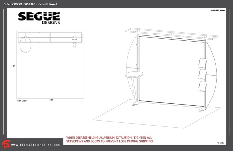
VISIONARY DESIGNS SEGUE VK-1308 User manual

VISIONARY DESIGNS

VISIONARY DESIGNS SEGUE VK-1308 User manual

VISIONARY DESIGNS RE-1067 Manual

VISIONARY DESIGNS

VISIONARY DESIGNS RE-1067 Manual

VISIONARY DESIGNS MOD-1454 Manual

VISIONARY DESIGNS

VISIONARY DESIGNS MOD-1454 Manual

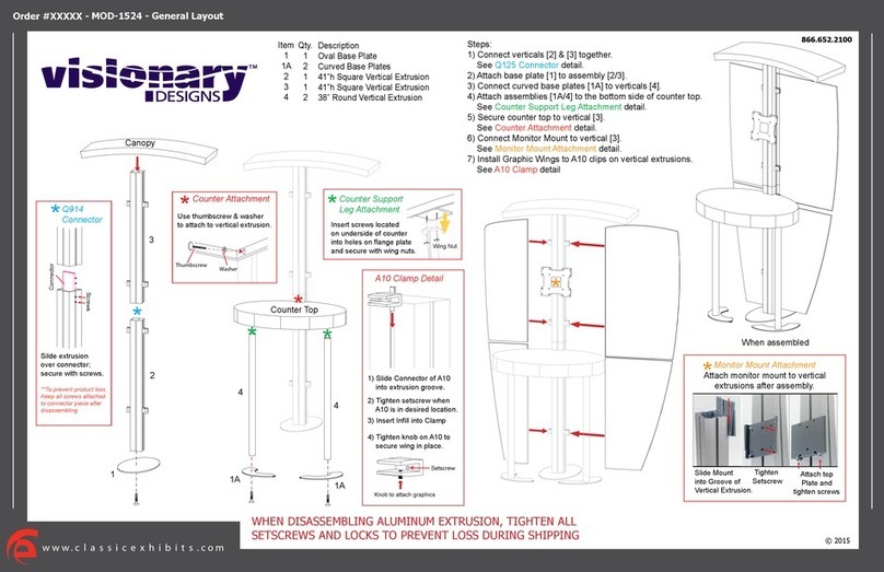
VISIONARY DESIGNS MOD-1524 Manual

VISIONARY DESIGNS

VISIONARY DESIGNS MOD-1524 Manual

VISIONARY DESIGNS MOD-1441 User manual

VISIONARY DESIGNS

VISIONARY DESIGNS MOD-1441 User manual

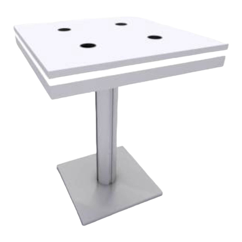
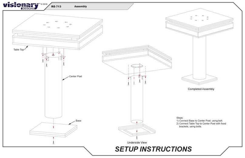
VISIONARY DESIGNS RE-713 Manual

VISIONARY DESIGNS

VISIONARY DESIGNS RE-713 Manual

VISIONARY DESIGNS VK-1320 Manual

VISIONARY DESIGNS

VISIONARY DESIGNS VK-1320 Manual

VISIONARY DESIGNS MOD-1514 Manual

VISIONARY DESIGNS

VISIONARY DESIGNS MOD-1514 Manual

VISIONARY DESIGNS TF-523 Manual

VISIONARY DESIGNS

VISIONARY DESIGNS TF-523 Manual

VISIONARY DESIGNS MOD-1279 User manual

VISIONARY DESIGNS

VISIONARY DESIGNS MOD-1279 User manual

VISIONARY DESIGNS MOD-1525 Manual

VISIONARY DESIGNS

VISIONARY DESIGNS MOD-1525 Manual

VISIONARY DESIGNS LTK-1115 Manual

VISIONARY DESIGNS

VISIONARY DESIGNS LTK-1115 Manual

VISIONARY DESIGNS VK-1334 Manual

VISIONARY DESIGNS

VISIONARY DESIGNS VK-1334 Manual

Popular Indoor Furnishing manuals by other brands

Abt 1595-80113-LTBK Assembly instruction

Abt

Abt 1595-80113-LTBK Assembly instruction

VECELO KHD-LT-T06 Assembly instruction

VECELO

VECELO KHD-LT-T06 Assembly instruction

VITRA 1959/1999 Assembly instructions

VITRA

VITRA 1959/1999 Assembly instructions

Habitat Iaman 807775 manual

Habitat

Habitat Iaman 807775 manual

AIS Day to Day Series manual

AIS

AIS Day to Day Series manual

SNUGSQUARE IDO PEDESTAL Assembly instructions

SNUGSQUARE

SNUGSQUARE IDO PEDESTAL Assembly instructions

Hay HACKNEY LOUNGE instruction manual

Hay

Hay HACKNEY LOUNGE instruction manual

Coaster 203501KE Assembly instructions

Coaster

Coaster 203501KE Assembly instructions

Kettler ELEGANCE HUC28081 manual

Kettler

Kettler ELEGANCE HUC28081 manual

Trinity CTBFPBR-2701 owner's manual

Trinity

Trinity CTBFPBR-2701 owner's manual

Hillsdale Furniture Clarion quick guide

Hillsdale Furniture

Hillsdale Furniture Clarion quick guide

Mocka Olsen Entertainment Unit Assembly instructions

Mocka

Mocka Olsen Entertainment Unit Assembly instructions

JWA EDMUNDSTON 69619 Assembly instruction

JWA

JWA EDMUNDSTON 69619 Assembly instruction

Till-Hilft 87020.731 Assembly instructions

Till-Hilft

Till-Hilft 87020.731 Assembly instructions

Crate&Barrel Arch manual

Crate&Barrel

Crate&Barrel Arch manual

Sunset Trading DLU-TPD-4242-B Assembly instructions

Sunset Trading

Sunset Trading DLU-TPD-4242-B Assembly instructions

Ferm PEKA Assembly manual

Ferm

Ferm PEKA Assembly manual

Azteca S205-TOL1D1S Assembly

Azteca

Azteca S205-TOL1D1S Assembly

manuals.online logo
manuals.online logoBrands
  • About & Mission
  • Contact us
  • Privacy Policy
  • Terms and Conditions

Copyright 2025 Manuals.Online. All Rights Reserved.