Würth master EH 4 User manual

EH 4
Bedienungsanleitung
Operating Instructions
Istruzioni d’uso
Notice d’utilisation
Instrucciones para el manejo
Instruções de utilização
Gebruiksaanwijzing
Betjeningsvejledning
Bruksanvisning
Käyttöohje
Bruksanvisning
Οδηγίεσ χειρισµού
Kullanım kılavuzu
Instrukcja obs∆ugi
Kezelési Utasítás
Návod k obsluze
Návod na obsluhu
Instrucøiuni de utilizare
Navodila za uporabo
Ръководство на потребителя
Kasutusjuhend
Vartojimo informacijà
EkspluatÇcijas instrukcija
Руководство по эксплуатации
EH 4book Seite 1 Dienstag, 24. Januar 2006 11:50 11

PL
H
CZ
SK
RO
SLO
BG
EST
LT
LV
RUS
D
GB
I
F
E
P
NL
DK
N
FIN
S
GR
TR
.............................. 6... 9
............................. 10... 13
............................... 14... 18
............................... 19... 23
............................... 24... 28
............................... 29... 33
............................... 34... 38
............................... 39... 42
............................... 43... 46
............................... 47... 50
............................... 51... 54
............................... 55... 59
............................... 60... 64
............................... 65... 69
............................... 70... 74
............................... 75... 78
............................... 79... 83
................................84... 88
............................... 89... 93
............................... 94... 98
............................... 99... 103
............................. 104... 108
............................. 109... 113
............................. 114... 118
EH 4 - Inhalt Seite 2 Dienstag, 24. Januar 2006 1:21 13

A
1
3
1
2
3
4
5
7 8
9
10
12
11
6
13
15
16
14
EH 4book Seite 3 Dienstag, 24. Januar 2006 11:50 11

D E
B C
2 6 17 18 19
20 21
6
22 1
4
EH 4book Seite 3 Dienstag, 24. Januar 2006 11:50 11

H I
F G
23
26
22
4 1
24
22
27 28 29
25
EH 4book Seite 3 Dienstag, 24. Januar 2006 11:50 11

6
Gerätekennwerte
Bestimmungsgemäßer Gebrauch
Das Gerät ist dazu bestimmt bei fester Auflage Holz-
werkstoffe wie z. B. Balken und Bretter zu hobeln. Es
eignet sich auch zum Abschrägen von Kanten und
zum Falzen.
Für Schäden bei nicht bestimmungsgemäßem
Gebrauch haftet der Benutzer.
Fragen zum Gerät und seiner Anwendung beant-
wortet Ihnen in Deutschland die Produkt- und
Anwendungsberatung unter Tel.: 01805-60 65 69
(12 Cent/min).
Elektrohobel EH 4
Artikelnummer 0702 816 X
Nennaufnahme 1050 W
Leerlaufdrehzahl 13500 min
–1
Hobellänge 320 mm
Hobelbreite 82 mm
Spantiefe 4,0 mm
Falztiefe 25 mm
Gewicht 4,0 kg
Schutzklasse /
II
Zu Ihrer Sicherheit
Gefahrloses Arbeiten mit dem
Gerät ist nur möglich, wenn Sie die
Bedienungsanleitung und die
Sicherheitshinweise vollständig
lesen und die darin enthaltenen
Anweisungen strikt befolgen. Zusätzlich müssen
die allgemeinen Sicherheitshinweise im beige-
fügten Heft befolgt werden.
Das Gerät darf nicht feucht sein und
auch nicht in feuchter Umgebung
betrieben werden.
Wird bei der Arbeit das Netzkabel
beschädigt oder durchtrennt, Kabel
nicht berühren, sondern sofort den
Netzstecker ziehen. Gerät niemals
mit beschädigtem Kabel benutzen.
Schutzbrille, Schutzhandschuhe und
festes Schuhwerk tragen.
❏Beim Arbeiten entstehender Staub kann
gesundheitsschädlich, brennbar oder explosiv
sein. Geeignete Schutzmaßnahmen sind erfor-
derlich.
❏Greifen Sie nicht mit den Händen in den Spa-
nauswurf. Sie können sich an rotierenden Tei-
len verletzen.
❏Führen Sie das Elektrowerkzeug nur einge-
schaltet gegen das Werkstück. Es besteht sonst
die Gefahr eines Rückschlages, wenn sich das
Einsatzwerkzeug im Werkstück verhakt.
❏Halten Sie den Hobel beim Arbeiten immer so,
dass die Grundplatte flach auf dem Werkstück
aufliegt. Der Hobel kann sich sonst verkanten
und zu Verletzungen führen.
❏Hobeln Sie nie über Metallgegenstände,
Nägel oder Schrauben. Messer und Messer-
welle können beschädigt werden und zu erhöh-
ten Vibrationen führen.
❏Warten Sie den Stillstand der Messerwelle ab,
bevor Sie das Gerät ablegen. Eine freiliegende
Messerwelle kann sich mit der Oberfläche ver-
haken und zum Verlust der Kontrolle sowie
schweren Verletzungen führen.
❏Keine Werkzeugschlüssel stecken lassen.
❏Bei langen Haaren Haarschutz tragen. Nur mit
enganliegender Kleidung arbeiten.
❏Beim Arbeiten das Gerät immer fest mit beiden
Händen halten und für einen sicheren Stand
sorgen.
❏Anschlußkabel stets vom Wirkungsbereich der
Maschine fernhalten. Kabel immer nach hinten
vom Gerät wegführen.
❏Niemals Kindern die Benutzung des Gerätes
gestatten.
❏Zur Kennzeichnung des Gerätes nicht in das
Gehäuse bohren oder Nieten anbringen. Die
Schutzisolation ist dann nicht mehr gewährleis-
tet. Verwenden Sie Klebeschilder.
❏Nur Original-Würth-Zubehör verwenden!
D
☞Weitere Sicherheitshinweise siehe Beilage
EH 4book Seite 6 Dienstag, 24. Januar 2006 11:50 11

7
Geräteelemente
1
Spanauswurf (links/rechts)
2
Spantiefeneinstellung
3
Spantiefenskala
4
Umschalthebel für Spanauswurf
5
Grundplatte
6
Gewinde für Parallelanschlag/
Falztiefenanschlag
7
Ein-/Ausschalter
8
Einschaltsperre
9
Parkschuh
10
Hobelmesser
11
Falzschutz
12
V-Nuten
13
Spannschrauben
14
Messerhalter
15
Justierschrauben für Höheneinstellung
16
Messerwelle
17
Parallelanschlag
18
Flügelmutter
19
Befestigungsschraube für Parallelanschlag
20
Befestigungsschraube für Falztiefenanschlag
21
Falztiefenanschlag
22
Absaugadapter
23
Verschluss
24
Reduzierstück
25
Zwischenadapter
26
Staubsack
27
Deckel
28
Aussparung
29
Zapfen
Abgebildetes oder beschriebenes Zubehör gehört teilweise
nicht zum Lieferumfang.
Hobelmesser wechseln (Bild A)
Vor allen Arbeiten am Gerät Netzste-
cker ziehen.
Zum Einsetzen und Wechseln des
Hobelmessers Schutzhandschuhe
tragen.
Hobelmesser ausbauen
– Zum Wenden oder Ersetzen des Hobelmessers
Messerwelle
16
in entsprechende Position brin-
gen (siehe Bild).
– Schrauben
13
mit dem im Lieferumfang enthal-
tenen Gabelschlüssel lösen.
– Falzschutz
11
wegklappen.
– Messerwelle
16
etwas drehen und Messerhal-
ter
14
mit Holzstück seitlich aus der Messerwelle
herausschieben.
– Hobelmesser
10
vom Messerhalter
14
heraus-
ziehen.
– Stark verharzte Hobelmesser am besten vorher
mit Spiritus bzw. Petroleum behandeln.
Wechseln Sie immer beide Hobelmesser aus.
Hobelmesser einsetzen
Vor dem Wiedereinsetzen eines neuen bzw. gewen-
deten Hobelmessers
10
gegebenfalls dieses sowie
den Messerhalter von Schmutz befreien.
Bei der Montage ist darauf zu achten, dass der Mes-
serhalter
14
einwandfrei in der Aufnahmeführung
der Messerwelle
16
sitzt.
Hinweis:
Um einwandfrei falzen zu können ist es
wichtig, dass das Hobelmesser an der Seitenkante
der hinteren Hobelsohle bündig ausgerichtet wird.
Dies kann beispielsweise mit einem geraden Holz-
stück (Lineal) überprüft werden (siehe Bild).
Hobelmesser
10
/Messerhalter
14
entsprechend
ausrichten und Schrauben
13
wieder gut festziehen.
Vor Wiederinbetriebnahme sind die Messer
auf festen Sitz und einwandfreien Lauf zu
prüfen.
Hobelmesser einstellen
Vor der ersten Inbetriebnahme oder bei ungleich-
mäßigem Abtrag muss eine Höheneinstellung der
Hobelmesser durchgeführt werden.
– Spantiefe auf
0 mm
einstellen
– Messerwelle soweit drehen, bis Hobelmesser an
der höchsten Stelle steht.
– Großflächiges, gerades Holzstück auf den hinte-
ren Teil der Grundplatte und der Messerkante
auflegen.
– Die beiden Justierschrauben
15
solange verdre-
hen bis Hobelmesser
10
bündig an der Oberflä-
che des Holzstückes aufliegt.
Messerwelle drehen und den Vorgang für das
zweite Hobelmesser wiederholen.
Inbetriebnahme
Netzspannung beachten:
Die Spannung der Strom-
quelle muss mit den Angaben auf dem Typschild des
Gerätes übereinstimmen.
Ein-/Ausschalten
Einschalten:
Einschaltsperre
8
drücken, danach
Ein-/Ausschalter
7
betätigen.
Ausschalten:
Ein-/Ausschalter
7
wieder loslassen.
EH 4book Seite 7 Dienstag, 24. Januar 2006 11:50 11

8
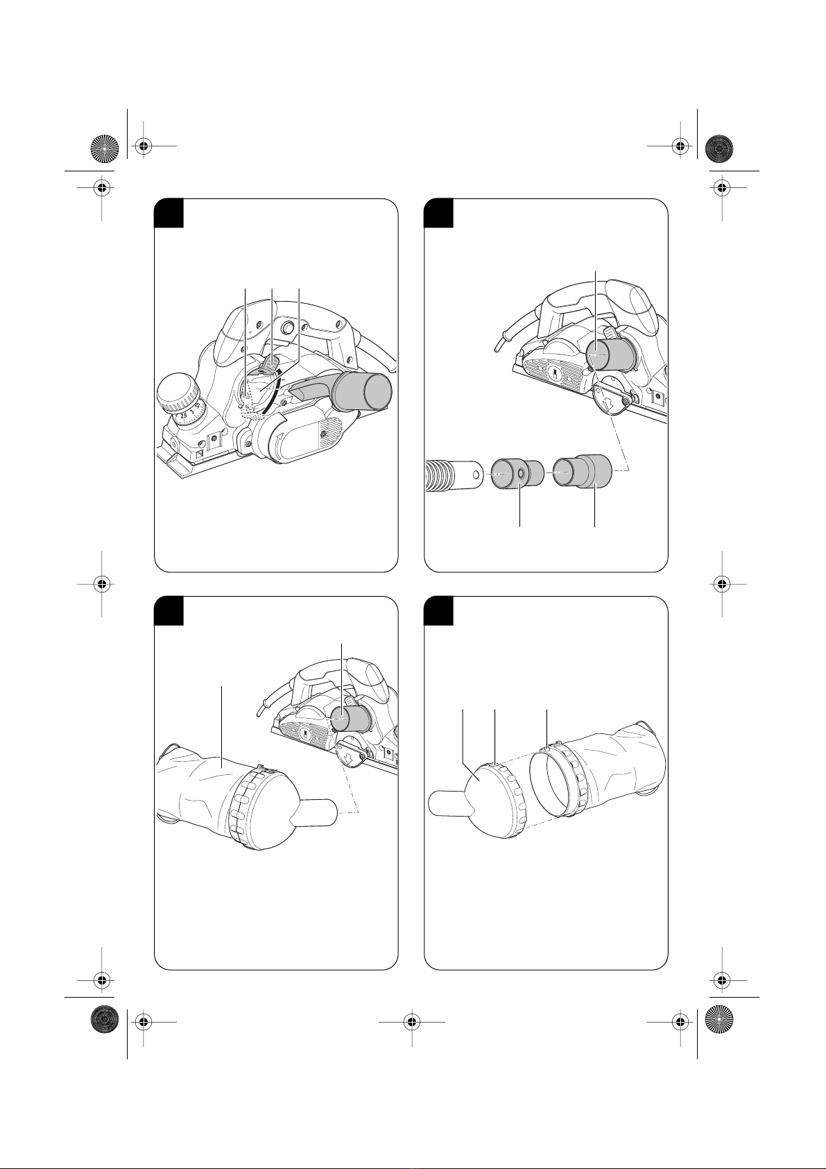
Spantiefe einstellen (Bild B)
Mit dem Führungsgriff
2
kann die Spantiefe stufen-
weise von 0 - 4,0 mm eingestellt werden:
Durch Drehen des Führungsgriffes
2
können auf der
Skala
3
die gewünschten Spantiefen eingestellt wer-
den. Dabei Führungsgriff
2
immer soweit drehen bis
dieser spürbar einrastet.
Parkschuh
Das Gerät ist mit einem Parkschuh
9
ausgestattet.
Dieser ermöglicht ein Abstellen des Gerätes unmit-
telbar nach dem Arbeitsvorgang, ohne die Gefahr
einer Beschädigung von Werkstückoberfläche oder
Hobelmesser.
Parallelanschlag (Bild C)
Der Parallelanschlag
17
dient zur besseren Führung
der Maschine beim Hobeln von schmalen Werkstük-
ken und zur Begrenzung der Falzbreite.
– Parallelanschlag
17
links oder rechts mittels
Winkel im Gewindeloch
6
montieren.
– Befestigungsschraube 19 festziehen.
– Die Falzbreite mittels Flügelmutter 18 einstellen.
Falztiefenanschlag (Bild D)
– Montieren Sie den Falztiefenanschlag 21 mit
der Befestigungsschraube 20.
– Falztiefenanschlag mittels Skala auf die ge-
wünschte Höhe einstellen und Befestigungs-
schraube festziehen.
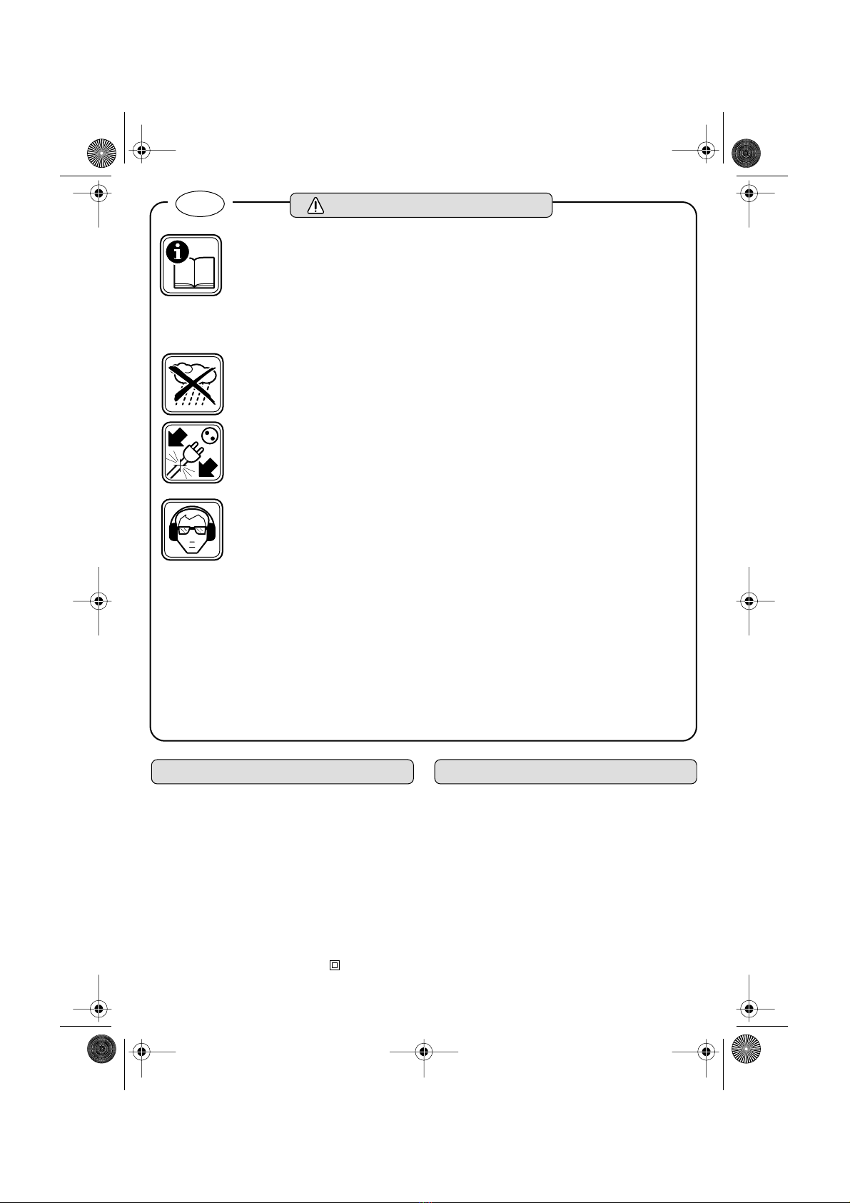
Spanauswurf/Spanabsaugung
Beim Arbeiten entstehender Staub kann gesund-
heitsschädlich, brennbar oder explosiv sein.
Geeignete Schutzmaßnahmen sind erforderlich.
Manche Stäube gelten als krebserregend. Staub-/
Spanabsaugung verwenden und Staubschutz-
maske tragen!
Wählbarer Spanauswurf (Bild E/F)
Mit dem Umschalthebel 4 kann der Spanauswurf 1
nach rechts oder links umgestellt werden.
Absaugadapter 22 soweit in den Spanauswurf drü-
cken, bis er einrastet.
Zum Abnehmen Umschalthebel 4 nach oben ziehen
und Absaugadapter 22 herausziehen.
Bei linksseitigem Spanauswurf muss immer eine
Fremdabsaugung mit Staubsauger verwendet wer-
den, um eine Verstopfung zu vermeiden.
Den Spanauswurf 1 und den Verschluss 23 regel-
mäßig reinigen. Nicht mit den Fingern in den Spa-
nauswurf greifen!
Fremdabsaugung mit Staubsauger (Bild G)
Reduzierstück 24 auf Absaugschlauch stecken und
bis zum Einrasten drehen (Clip-System).
Zwischenadapter 25 auf Absaugadapter 22 ste-
cken und Absaugschlauch mit Reduzierstück
anschließen.
Würth bietet geeignete Staubsauger an. Das Gerät
kann an der Steckdose eines Würth-Staubsaugers
mit Automatikbetrieb direkt angeschlossen werden.
Beim Einschalten des Gerätes wird der Staubsauger
automatisch gestartet.
Eigenabsaugung mit Staubsack (Bild H/I)
Für kleinere Arbeiten kann der Staubsack 26 ver-
wendet werden (nur bei rechtsseitigem Spanauswurf
möglich). Staubsack 26 fest auf Absaugadapter 22
drücken.
Zum Reinigen und Entleeren des Staubsackes den
Deckel 27 etwas drehen und abziehen.
Beim Zusammenbau darauf achten, dass der Zap-
fen 29 in die Aussparung 28 eingreift (Bajonettver-
schluss).
Arbeitshinweise
❏Zu starker Vorschub mindert erheblich das Leis-
tungsvermögen des Gerätes und verringert die
Lebensdauer der Messer.
❏Nur scharfe Hobelmesser bringen gute Schnitt-
leistung und schonen das Gerät.
❏Messer rechtzeitig erneuern. Entsprechende Qua-
lität garantiert das Würth-Zubehör-Programm.
Flächen hobeln
Das Gerät eingeschaltet an das Werkstück heranfüh-
ren und darauf achten, dass die vordere Grundplatte
ganzflächig auf der Werkstückoberfläche aufliegt.
Wird das Gerät direkt auf das Werkstück
aufgesetzt besteht Rückschlaggefahr durch
das laufende Hobelmesser!
Den Hobel mit beiden Händen und gleichmäßigem
Vorschub über die zu bearbeitende Fläche führen.
Beim Glatthobeln von Flächen empfiehlt es sich, nur
geringe Spantiefen einzustellen und den Hobelvor-
gang mehrmals zu wiederholen.
EH 4book Seite 8 Dienstag, 24. Januar 2006 11:50 11

9
Kanten anfasen
Die in der vorderen Hobelsohle befindlichen V-
Nuten 12 ermöglichen schnelles und einfaches
Anfasen von Werkstückkanten.
Dazu den Hobel mit V- Nut auf die Werkstückkante
aufsetzen und an dieser entlangführen.
Während des Anfasvorganges auf konstante Win-
kellage (45°) und gleichmäßigen Vorschub achten.
Wartung und Reinigung
❏Vor allen Arbeiten am Gerät Netzstecker zie-
hen.
☞Gerät und Lüftungsschlitze stets sauber halten,
um gut und sicher zu arbeiten.
Sollte das Gerät trotz sorgfältiger Herstell- und Prüf-
verfahren einmal ausfallen, ist die Reparatur von
einem Würth master-Service ausführen zu lassen. In
Deutschland erreichen Sie den Würth master-Ser-
vice kostenlos unter Tel. 0800-WMASTER (0800-9
62 78 37). In Österreich unter der Tel. 0800-20 30
13.
Bei allen Rückfragen und Ersatzteilbestellungen bitte
unbedingt die 8-stellige Artikelnummer laut Typen-
schild des Gerätes angeben.
Die aktuelle Ersatzteilliste dieses Gerätes kann im
Internet unter „http://www.wuerth.com/partsma-
nager“ aufgerufen oder von der nächstgelegenen
Würth-Niederlassung angefordert werden.
Entsorgung
Elektrowerkzeuge, Zubehör und Verpackungen sol-
len einer umweltgerechten Wiederverwertung zuge-
führt werden.
Nur für EU-Länder:
Werfen Sie Elektrowerkzeuge nicht
in den Hausmüll!
Gemäß der Europäischen Richtlinie
2002/96/EG über Elektro- und
Elektronik-Altgeräte und ihrer
Umsetzung in nationales Recht müssen nicht mehr
gebrauchsfähige Elektrowerkzeuge getrennt gesam-
melt und einer umweltgerechten Wiederverwertung
zugeführt werden.
Würth nimmt Ihr defektes Würth-Gerät gerne kos-
tenlos zurück.
Gewährleistung
Für dieses Würth-Gerät bieten wir eine Gewährlei-
tung gemäß den gesetzlichen/länderspezifischen
Bestimmungen ab Kaufdatum (Nachweis durch
Rechnung oder Lieferschein). Entstandene Schäden
werden durch Ersatzlieferung oder Reparatur besei-
tigt.
Schäden, die auf natürliche Abnutzung, Überlas-
tung oder unsachgemäße Behandlung zurückzufüh-
ren sind, werden von der Garantie ausgeschlossen.
Beanstandungen können nur anerkannt werden,
wenn Sie das Gerät unzerlegt einer Würth-Nieder-
lassung, Ihrem Würth-Außendienstmitarbeiter oder
einer Würth-autorisierten Kundendienststelle für
Elektrowerkzeuge übergeben.
Geräusch-/
Vibrationsinformation
Meßwerte ermittelt entsprechend EN 60 745.
Der A-bewertete Geräuschpegel des Gerätes
beträgt typischerweise: Schalldruckpegel
87,3 dB (A); Schalleistungspegel 98,3 dB (A).
Gehörschutz tragen!
Die bewertete Beschleunigung beträgt typischer-
weise 2,96 m/s2.
Konformitätserklärung
Wir erklären in alleiniger Verantwortung, dass die-
ses Produkt mit den folgenden Normen oder norma-
tiven Dokumenten übereinstimmt: EN 55014-1,
EN 55014-2, EN 61000-3-2, EN 61000-3-3,
EN 60745 gemäß den Bestimmungen der Richtli-
nien 73/23 EWG, 89/336/EWG, 98/37/EWG.
05
Adolf Würth GmbH & Co. KG
P. Zürn R. Bauer
Änderungen vorbehalten
EH 4book Seite 9 Dienstag, 24. Januar 2006 11:50 11

10
Tool Specifications Use as intended
The machine is intended for the planing of wood
materials such as beams and board while resting
firmly on the workpiece. It is also suitable for struc-
turing with rustic cutter blades, for chamfering of
edges and rebating.
For damage caused by usage other then intended,
the user is responsible.
Electro-Planer EH 4
Order number 0702 816 X
Rated power consumption 1050 W
No-load speed 13500 rpm
Planer length 320 mm
Planer width 82 mm
Chip depth 4,0 mm
Rebate depth 25 mm
Weight 4.0 kg
Protection class /II
For Your Safety
Working safely with this machine
is possible only when the operating
and safety information are read
completely and the instructions
contained therein are strictly fol-
lowed. In addition, the general safety notes in
the enclosed booklet must be observed.
The machine must not be damp and
must also not be operated in damp
surroundings.
If the mains cable is damaged or cut
through while working, do not touch
the cable but immediately pull the
mains plug. Never use the machine
with a damaged cable.
Wear safety glasses, protective
gloves and sturdy shoes.
❏Dust developing during work can be harmful
to one’s health, combustible or explosive. Sui-
table protective measures are required.
❏Do not reach into the chip ejector with your
hands. They could be injured by rotating parts.
❏Guide the machine against the workpiece only
when it is switched on. Otherwise there may be
danger of kickback when the tool insert jams in
the workpiece.
❏When working, always hold the planer in
such a manner that the base plate faces flat on
the workpiece. Otherwise the planer can
become wedged and lead to injuries.
❏Never plane over metal objects, nails or
screws. The planer blade and the blade shaft
can become damaged and lead to increased
vibrations.
❏Wait for the blade shaft to stop before setting
the machine down. An exposed blade shaft
can seize with the surface, leading to possible
loss of control and serious injury.
❏Do not leave the chuck key inserted.
❏For long hair, wear hair protection. Work only
with close-fitting clothes.
❏When working with the machine, always hold
it firmly with both hands and provide for a
secure stance.
❏Keep mains lead clear from working range of
the machine. Always direct the cable to the rear
away from the machine.
❏Never allow children to use the machine.
❏Do not drill into housing or attach rivets in order
to mark the machine. The double insulation is
then no longer ensured. Use stickers.
❏Use only original Würth parts and accesso-
ries.
GB
☞For further notes on safety refer to the enclosed sheet
EH 4book Seite 10 Dienstag, 24. Januar 2006 11:50 11

11
Operating controls
1 Chip ejector (left/right)
2 Planing depth adjustment
3 Planing depth scale
4 Chip ejection selection lever
5 Base plate
6 Thread for parallel guide/rebating depth stop
7 On/Off switch
8 Lock-off button
9 Park rest
10 Planer blade
11 Rebating protector
12 V-grooves
13 Clamping bolts
14 Blade holder
15 Adjusting screws for height adjustment
16 Blade shaft
17 Parallel guide
18 Wing nut
19 Fastening screw for parallel guide
20 Fastening screw for rebating depth stop
21 Rebating depth stop
22 Extraction adapter
23 Lock
24 Reducer
25 Adapter
26 Dust bag
27 Lid
28 Notch
29 Catch
Not all of the accessories illustrated or described
are included as standard delivery.
Replacing the Planer Cutter
Blade (Figure A)
Before all work on the machine itself,
pull the mains plug.
Wear protective gloves for inserting
and changing the planer cutter
blades.
Removing the Planer Cutter Blades
– For reversing or inserting the planer cutter blades,
bring the cutter head 16 to the appropriate posi-
tion (see Figure).
– Loosen the screws 13 with the Allen key provided
with the machine.
– Fold away the rebate protector 11.
– Turn the cutter head 16 somewhat and slide the
cutter blade holder 14 to the side out of the cutter
head with a piece of wood.
– Pull the cuter blade 10 from the cutter blade hol-
der 14.
– It is best to clean heavily gummed cutter blades
with alcohol or paraffin.
Always replace both planer cutter blades.
Inserting the Planer Cutter Blades
Before reinserting a new or a reversed planer cutter
blade 10, remove dirt from it as well as from the cut-
ter blade seat.
Care is to be taken when mounting that the cutter
blade holder 14 is seated properly in the holder
guide of the cutter head 16.
Note: To be able to rebate flawlessly, it is important
that the planer cutter blades are aligned with the
side edge of the rear planer base plate. This can be
checked with a straight piece of wood (ruler), for ex-
ample (see Figure).
Align the cutter blade 10/cutter blade holder 14
accordingly and firmly tighten the screws 13.
Before returning to operation, the cutter
blades are to be checked for firm seating
and flawless running.
Adjusting the Planer Blades
Before starting operation for the first time or in case
of irregular material removal, the height of the pla-
ner blades must be adjusted.
– Set the planing depth to 0 mm.
– Turn the blade shaft until the planer blade is at the
highest position.
– Position a large-surface, straight piece of wood
onto the rear of the base plate and the edge of the
blade.
– Turn both adjusting screws 15 until the planer
blade 10 faces flush against the surface of the
wood piece.
Turn the blade shaft and repeat the procedure for
the second planer blade.
Initial operation
Always use the correct supply voltage: The power
supply voltage must match the information quoted
on the tool identification plate.
EH 4book Seite 11 Dienstag, 24. Januar 2006 11:50 11

12
Switching on/off
Switching on: Press lockoff 8 followed by ON/
OFF switch 7.
Switching off: Release ON/OFF switch 7.
Setting the cutting depth (Figure B)
The cutting depth 2 can be set in steps from 0 -
4.0 mm with guide switch:
The desired cutting depth can be set on scale 3 by
rotating guide switch 2. Always rotate guide
switch 2 until it engages.
Parking Shoe
The machine is equipped with a parking shoe 9.
This makes possible the placing down of the ma-
chine immediately after the working process without
the danger of damaging the workpiece surface or
the planer cutter blades.
If the parking shoe is not needed, it can be lock in
the horizontal position.
Parallel Guide (Figure C)
The parallel guide 17 serves for better guiding of the
machine when planing small workpieces and for
limiting the rebating width.
– Mount the parallel guide 17 on the left or right by
means of the bracket in the threaded hole 6.
– Tighten fastening screw 19.
– Adjust the rebating width with the wing nut 18.
Mounting, Dismounting and Adjusting of
the Rebate Depth Stop (Figure D)
– Mount the rebating depth stop 21 with the faste-
ning screw 20.
– Adjust the rebating depth stop to the required
height with the scale and tighten the fastening
screw.
Chip Ejection/Chip Extraction
Dust developing during work can be harmful to
one’s health, combustible or explosive. Suitable
protective measures are required.
Some dusts are regarded as carcinogenic. Work
with dust/chip extraction and wear a dust mask!
Choice of Chip Ejector Side (Fig. E/F)
The chip ejector 1 can be switched to the right or left
with the selector lever 4.
Push the extraction adapter 22 into the chip ejector
until it latches.
For removal, push the selector lever 4 upward and
pull out the extraction adapter 22.
When chip ejection is on the left side, external dust
extraction with a vacuum cleaner must always be
used in order to avoid clogging.
Clean the chip ejector 1 and the lock 23 regularly.
Do not reach into the chip ejector with your fingers!
External Dust Extraction with Vacuum
Cleaner (Fig. G)
Attach reducer 24 onto vacuum hose and turn until
it latches (clip system).
Attach adapter 25 onto extraction adapter 22 and
connect vacuum hose with reducer.
Würth provides suitable vacuum cleaners. The
machine can be connected directly to the socket out-
let of a Würth vacuum cleaner with remote control
operation. When starting the machine, the vacuum
cleaner is automatically started.
Integrated Dust Extraction with Dust Bag
(Fig. H/I)
The dust bag 26 can be used for smaller jobs (only
possible for chip ejection on the right-hand side).
Press the dust bag 26 firmly onto the extraction
adapter 22.
For cleaning and emptying the dust bag, lightly turn
the lid 27 and pull off.
Upon reassembly, pay attention that the catch 29
engages into the notch 28 (bayonet catch).
Operating instructions
❏Advancing that is too fast reduces significantly the
performance capability of the machine and short-
ens the service life of the cutter blades.
❏Only sharp planer cutter blades produce good
cutting performance and protect the machine.
❏Replace the cutter blades before they become too
dull. Appropriate quality is ensured by the Würth
accessory program.
Surface Planing
Apply the machine while switched on to the work-
piece and take care that the front base plate rests
completely on the workpiece surface.
If the machine is placed directly onto the
workpiece, the danger of kicking back exists
as a result of the rotating cutter blades!
Guide the planer with both hands and uniform ad-
vancing over the surface to be worked.
EH 4book Seite 12 Dienstag, 24. Januar 2006 11:50 11

13
For the flat planing of surfaces, it is recommended
that a small chip depth be set and the planing pass
be repeated several times.
Chamfering of Edges
Located in the middle of the front base plate of the
planer is a V-groove 12 that makes possible quick
and easy chamfering of workpiece edges.
For this purpose, place the V-groove of the planer on
the workpiece edge and guide along.
During the chamfering, take care to maintain a con-
stant position angle (45°) and uniform advancing.
Maintenance and Cleaning
❏Before any work on the machine itself, pull the
mains plug.
☞For safe and proper working, always keep the
machine and the ventilation slots clean.
If the machine should fail despite the care taken in
manufacturing and testing, repair should be carried
out by a Würth Master-Service agent.
In all correspondence and spare parts orders,
please always include the 8-digit order number
given on the nameplate of the machine.
For the current spare parts list of this machine, log into
the Internet under “http://www.wuerth.com/parts-
manager” or ask for a copy at your nearest Würth
branch office.
Disposal
Power tools, accessories and packaging should be
sorted for environmental-friendly recycling.
Only for EC countries:
Do not dispose of power tools into
household waste!
According to the European Directive
2002/96/EC on waste electrical
and electronic equipment and its
incorporation into national law, power tools that are
no longer suitable for use must be separately col-
lected and sent for recovery in an environmental-
friendly manner.
Würth will gladly take back your defective Würth
power tool free of charge.
Warranty
For this Würth tool, we provide a warranty in
accordance with statutory/country-specific regula-
tions from the date of purchase (proof of purchase
by invoice or delivery note). Damage that has
occurred will be corrected by replacement or repair.
Damage caused by normal wear, overloading or
improper handling is excluded from the warranty.
Claims can be recognised only when the tool is pre-
sented undisassembled to a Würth branch office or
a Würth field service employee.
Noise/Vibration Information
Measured values determined according to
EN 60 745.
Typically the A-weighted noise levels of the machine
are: Sound pressure level: 87,3 dB (A); Sound pow-
er level: 98,3 dB (A).
Wear hearing protection!
The typically weighted acceleration is 2,96 m/s2.
Declaration of Conformity
We declare under our sole responsibility that this
product is in conformity with the following standards
or standardization documents: EN 55014-1,
EN 55014-2, EN 61000-3-2, EN 61000-3-3,
EN 60745 according to the provisions of the regu-
lations 73/23/EEC, 89/336/EEC, 98/37/EC.
05
Adolf Würth GmbH & Co. KG
P. Zürn R. Bauer
Subject to change without notice
EH 4book Seite 13 Dienstag, 24. Januar 2006 11:50 11

14
Dati tecnici Uso conforme alle norme
In caso di appoggi fissi, la macchina è idonea per
piallare materiali legnosi come per esempio travi e
tavole. Adatto anche per lavori di smussatura e di
scanalatura.
Per danni provocati da uso non conforme alle
norme, risponde esclusivamente l'Utente.
Pialletto elettrico EH 4
Codice di ordinazione 0702 816 X
Potenza assorbita nominale 1050 W
Numero di giri a vuoto 13500 min–1
Lunghezza del pialletto 320 mm
Larghezza del pialletto 82 mm
Profondità di passata 4,0 mm
Profondità di scanalatura 25 mm
Peso 4,0 kg
Classe di protezione /II
Per la Vostra sicurezza
È possibile lavorare con la macchina
senza incorrere in pericoli soltanto
dopo aver letto completamente le
istruzioni per l’uso e l’opuscolo
avvertenze per la sicurezza e
seguendo rigorosamente le istruzioni
in essi contenute. Inoltre vanno rispettate anche le
generali istruzioni di sicurezza riportate nell’opu-
scolo allegato.
La macchina non può essere umida né
può essere utilizzata in un ambiente
umido.
Se durante un’operazione di lavoro
viene danneggiato oppure troncato il
cavo dell’alimentazione di rete, non
toccare il cavo ma estrarre immediata-
mente la spina dalla presa. Mai utiliz-
zare la macchina con un cavo dan-
neggiato.
Portare occhiali di protezione, guanti
di protezione e scarpe di protezione.
❏La polvere prodotta durante la lavorazione può
essere dannosa per la salute, infiammabile
oppure esplosiva. È necessario prendere ade-
guate misure di protezione.
❏Non avvicinare mai le mani all'espulsione dei
trucioli. Le parti in rotazione costituiscono un con-
creto pericolo.
❏Avvicinare l'elettroutensile al pezzo in lavora-
zione solo quando è in azione. In caso contrario
vi è il pericolo di un contraccolpo in caso che
l'accessorio impiegato dovesse rimanere incep-
pato nel pezzo in lavorazione.
❏Durante la lavorazione tenere il pialletto sempre
in modo tale che il pattino poggi bene sul pezzo
in lavorazione. In caso contrario il pialletto può
prendere angolature improprie e provocare inci-
denti.
❏Non piallare mai oggetti metallici, chiodi oppure
viti. La lama di pialla e l'albero portalame potreb-
bero subire dei danni e provocare un aumento
delle vibrazioni.
❏Prima di posare la macchina, attendere che
l'albero portalame sia in posizione di riposo. Un
albero portalame non protetto potrebbe restare
agganciato con la superficie provocando la per-
dita del controllo e seri pericoli di incidenti.
❏Mai lasciare inseriti utensili.
❏In caso di capelli lunghi è necessario portare
un’adatta protezione per i capelli. Lavorare sol-
tanto con abiti adatti ed aderenti al corpo.
❏Durante le operazioni di lavoro è necessario
tenere la macchina sempre con entrambe le mani
ed adottare una posizione di lavoro sicura.
❏Tenere sempre lontano il cavo di collegamento
dall’area di lavoro dell’attrezzo.
❏Mai permettere a bambini di utilizzare la mac-
china.
❏Per contrassegnare la macchina, mai eseguire fori
nella carcassa della macchina, né applicarvi
rivetti. In tal caso non sarebbe più garantita l’iso-
lazione di protezione. Utilizzare targhette autoin-
collanti.
❏Impiegare solo accessori originali di Würth.
I
☞Per altre istruzioni di sicurezza si veda il foglio allegato
EH 4book Seite 14 Dienstag, 24. Januar 2006 11:50 11

15
Elementi della macchina
1 Espulsione dei trucioli (sinistra/destra)
2 Regolazione della profondità di passata
3 Scaletta della profondità di passata
4 Levetta di commutazione per espulsione dei
trucioli
5 Pattino
6 Filettatura per guida parallela/battuta per
scanalatura
7 Interruttore avvio/arresto
8 Pulsante di sicurezza
9 Piedino di protezione
10 Lama di pialla
11 Protezione scanalatura
12 Scanalature a V
13 Vite di serraggio
14 Supporto lama
15 Vite per la regolazione dell'altezza
16 Albero portalame
17 Guida parallela
18 Dado ad alette
19 Vite di fissaggio per guida parallela
20 Vite di fissaggio per battuta per scanalatura
21 Battuta per scanalatura
22 Raccordo aspiratore
23 Tappo
24 Elemento di riduzione
25 Adattatore intermedio
26 Sacchetto raccoglipolvere
27 Coperchio
28 Rientranza
29 Spinotto
Gli accessori illustrati o descritti nelle istruzioni per l’uso
non sono sempre compresi nella fornitura.
Sostituire le lame (Figura A)
Prima di qualunque intervento alla
macchina, estrarre la spina dalla presa
di rete.
Per applicare e sostituire la lama biso-
gna indossare dei guanti di protezione.
Smontare la lama
– Per girare oppure sostituire la lama della pialla-
trice, mettere la fresa a denti riportati 16 nella
rispettiva posizione (vedere figura).
– Allentare le viti 13 utilizzando la chiave a tubo
compresa nel volume di fornitura.
– Ribaltandola, aprire la protezione scanalatu-
ra 11.
– Girare leggermente la fresa a denti riportati 16
e, utilizzando un pezzetto di legno, spingere
fuori lateralmente il portalama 14 dalla fresa a
denti riportati.
– Sfilare la lama 10 dal portalama 14.
– In caso di lame fortemente incrostate, è con-
sigliabile trattarle prima con alcool oppure pe-
trolio.
Sostituire sempre e soltanto entrambe le lame.
Applicare la lama
Prima di riapplicare una lama nuova oppure una
lama girata 10, pulire bene sia la lama che la
rispettiva sede.
Durante il montaggio bisogna assicurarsi che il por-
talama 14 posi perfettamente nella guida attacco
utensili della fresa a denti riportati 16.
Avvertenza: Per poter eseguire scanalature alla per-
fezione è importante che la lama venga regolata
sullo spigolo laterale del pattino posteriore della
piallatrice. Questa posizione può essere verificata
per esempio utilizzando una tavoletta diritta (riga)
(cfr. figura).
Registrare propriamente la lama 10/portalama 14
e riavvitare bene le viti 13.
Prima di rimettere in esercizio la macchina,
accertarsi che la lama sia ben fissa e che giri
perfettamente
Regolazione della lama di pialla
Prima di mettere in esercizio la macchina per la
prima volta oppure in caso di asportazione non uni-
forme si deve eseguire una regolazione dell'altezza
delle lame di pialla.
– Regolare la profondità di passata su 0 mm
– Ruotare l'albero portalame quanto necessario
per far arrivare la lama di pialla al punto più alto.
– Prendere un pezzo di legno diritto che abbia una
superficie di una certa dimensione ed applicarlo
alla parte posteriore del pattino e del bordo della
lama.
– Ruotare le due viti di regolazione 15 fino a
quando la lama di pialla 10 sarà arrivata a pog-
giare a filo con la superficie del pezzo di legno.
Ruotare l'albero portalame e ripetere l'operazione
per la seconda lama di pialla.
EH 4book Seite 15 Dienstag, 24. Januar 2006 11:50 11

16
Messa in funzione
Osservare la tensione di rete: La tensione della rete
deve corrispondere a quella indicata sulla targhetta
della macchina.
Inserimento/disinserimento
Inserimento: Premere il blocco inserimento 8 di
seguito azionare l'interruttore di
inserimento/disinserimento 7.
Disinserimento:Lasciare l'interruttore inserimen-to/
disinserimento 7.
Regolazione della profondità dello spesso-
re del truciolo (Figura B)
Con la presa di guida 2 è possibile la regolazione a
gradi da 0 - 4,0 mm, della profondità del truciolo.
Girando la presa di guida 2 possono venire regolate
sulla scala 3 le profondità desiderate. Per ottenere ciò,
girare la presa di guida 2 fino a quando non si sente lo
scatto d'innesto.
Guida parallela (Figura C)
La guida parallela 17 serve a dare alla macchina
una migliore guida durante i lavori di piallatura di
stretti pezzi in lavorazione e per la limitazione della
larghezza della scanalatura.
– Utilizzando un angolo, montare la guida paral-
lela 17 nel foro filettato 6 sul lato sinistro oppure
destro.
– Avvitare a fondo la vite di fissaggio 19.
– Regolare la larghezza della scanalatura
mediante il dado ad alette 18.
Battuta per scanalatura (Figura D)
– Montare la battuta per scanalatura 21 utiliz-
zando la vite di fissaggio 20.
– Regolare tramite la scala graduata la battuta per
scanalatura all'altezza richiesta e stringere forte
la vite di fissaggio.
Espulsione/aspirazione
dei trucioli
La polvere prodotta durante la lavorazione può
essere dannosa per la salute, infiammabile oppure
esplosiva. È necessario prendere adeguate misure
di protezione.
Alcune polveri sono considerate cancerogene. Uti-
lizzare un sistema di aspirazione della polvere/
trucioli e portare la maschera di protezione contro
la polvere!
Espulsione selezionabile dei trucioli
(Figura E/F)
Tramite la levetta di commutazione 4 è possibile
cambiare l'espulsione dei trucioli 1 verso destra
oppure verso sinistra.
Premere l'adattatore per l'aspirazione 22 quanto
necessario nell'espulsione dei trucioli fino allo scatto
in posizione dello stesso.
Per rimuoverlo, tirare in alto la levetta di commuta-
zione 4 ed estrarre il raccordo aspiratore 22.
In caso di espulsione dei trucioli sul lato sinistro si
deve utilizzare sempre un'aspirazione esterna con
aspiratore in modo da poter evitare un intasamento.
Pulire regolarmente l'espulsione dei trucioli 1 ed il
tappo 23. Non infilare mai le dita nell'espulsione
dei trucioli!
Aspirazione esterna con aspiratore
(Figura G)
Inserire l'elemento di riduzione 24 sul tubo di aspi-
razione e ruotarlo fino a quando se ne percepisce
l'incastro (Sistema Clip).
Applicare l'adattatore intermedio 25 sul raccordo
aspiratore 22 e collegare il tubo di aspirazione con
l'elemento di riduzione.
Würth propone una serie di aspiratori adatti. La
macchina può essere collegata direttamente alla
presa per la corrente di un aspiratore Würth con
funzionamento automatico. Accendendo la mac-
china l'aspiratore si avvia automaticamente.
EH 4book Seite 16 Dienstag, 24. Januar 2006 11:50 11

17
Aspirazione propria con sacchetto
raccoglipolvere (Figura H/I)
In caso di lavori minori è possibile utilizzare il sac-
chetto raccoglipolvere 26 (possibile solo in caso di
utilizzo di espulsione dei trucioli sulla destra). Eser-
citando la dovuta pressione, premere il sacchetto
raccoglipolvere 26 sul raccordo aspiratore 22.
Per pulire e svuotare il sacchetto raccoglipolvere,
ruotare leggermente il coperchio 27 e toglierlo.
Durante il montaggio accertarsi che lo spinotto 29
faccia presa nella rientranza 28 (innesto a baio-
netta).
Indicazioni pratiche
❏Avanzando troppo velocemente con la macchina
durante la lavorazione se ne riduce sensibilmente
la resa e si diminuisce la durata delle lame.
❏Soltanto lame ben affilate garantiscono ottime
prestazioni di taglio e non sottopongono la mac-
china a carichi superflui.
❏Sostituire in tempo le lame. Il programma acces-
sori Würth garantisce una rispettiva qualità.
Piallatura di superfici
Avvicinare la macchina al pezzo in lavorazione
quando la macchina è inserita ed assicurarsi che il
pattino anteriore della piallatrice poggi completa-
mente sulla superficie del pezzo in lavorazione.
Poggiando la macchina direttamente sul
pezzo in lavorazione vi è il pericolo che la
lama in azione provochi un pericoloso con-
traccolpo!
Operare con la piallatrice tenendola con entrambe
le mani ed avanzando uniformemente sulla superfi-
cie in lavorazione.
Piallando superfici a liscio, si consiglia di impostare
solo basse profondità di passata e di ripetere più
volte l'operazione di piallatura.
Smussare spigoli
La scanalatura V 12 che si trova nel centro del pat-
tino della piallatrice anteriore permette di smussare
in modo veloce e facile i bordi di un pezzo in lavo-
razione.
A tal fine, applicare la piallatrice con la scanalatura
V sullo spigolo del pezzo in lavorazione e guidare
la macchina lungo lo spigolo.
Durante la fase di smussatura di angoli, attenzione
a tenere la macchina sempre su una costante posi-
zione angolare (45°) ed ad avanzare sempre in
modo uniforme.
Manutenzione e pulizia
❏Prima di qualunque intervento alla macchina,
estrarre la spina dalla presa di rete.
☞Per poter garantire buone e sicure operazioni
di lavoro, tenere sempre pulite la macchina e
le fessure di ventilazione.
Se nonostante gli accurati procedimenti di produ-
zione e di controllo la macchina dovesse guastarsi,
la riparazione va fatta effettuare da un punto di
assistenza Würth master-Service autorizzato.
Comunicare sempre il codice di ordinazione a
8 cifre dell’elettroutensile in caso di richieste o di
ordinazione di pezzi di ricambio!
L’attuale distinta dei pezzi di ricambio di questa
macchina può essere consultata nel sito Internet
«http://www.wuerth.com/partsmanager» oppure
è possibile richiederla presso la più vicina filiale
Würth.
Smaltimento
Avviare ad un riciclaggio rispettoso dell’ambiente
gli imballaggi, gli elettroutensili e gli accessori
dismessi.
Solo per i Paesi della CE:
Non gettare elettroutensili dismessi
tra i rifiuti domestici!
Conformemente alla norma della
direttiva CE 2002/96 sui rifiuti di
apparecchiature elettriche ed elettro-
niche (RAEE) ed all’attuazione del recepimento nel
diritto nazionale, gli elettroutensili diventati inservi-
bili devono essere raccolti separatamente ed essere
inviati ad una riutilizzazione ecologica.
La Würth è disposta a ritirare gratuitamente la
Vostra macchina Würth difettosa.
EH 4book Seite 17 Dienstag, 24. Januar 2006 11:50 11

18
Garanzia legale
Per questo prodotto Würth, la garanzia è conforme
alle disposizioni di legge vigenti nei singoli Paesi, a
partire dalla data di acquisto (faranno fede la fat-
tura o la bolla di consegna). I difetti subentrati ven-
gono eliminati attraverso una fornitura di ricambio
oppure provvedendo alle dovute riparazioni.
Si esclude ogni prestazione di garanzia in caso di
danni dovuti a normale usura, a sovraccarico,
oppure a trattamento ed impiego inappropriato.
Si accettano reclami soltanto se il prodotto viene
rimandato indietro non smontato ad una delle sedi
Würth oppure al Responsabile di zona per il Servi-
zio Clienti Würth oppure ad un Centro Servizio
Clienti per Elettroutensili Würth autorizzato.
Informazioni sulla rumorosità
e sulla vibrazione
Valori misurati conformemente alla norma
EN 60 745.
La misurazione A del livello di pressione acustica
della macchina è di solito di: Livello di rumorosit
87,3 dB (A); Potenza della rumorosità 98,3 dB (A).
Utilizzare le cuffie di protezione!
L’accelerazione misurata raggiunge di solito il
valore di 2,96 m/s2.
Dichiarazione
di conformità
Assumendone la piena responsabilità, dichiariamo
che il prodotto è conforme alle seguenti normative
ed ai relativi documenti: EN 55014-1,
EN 55014-2, EN 61000-3-2, EN 61000-3-3,
EN 60745 in base alle prescrizioni delle direttive
CEE 73/23, CEE 89/336, CE 98/37.
05
Adolf Würth GmbH & Co. KG
P. Zürn R. Bauer
Con riserva di modifiche
EH 4book Seite 18 Dienstag, 24. Januar 2006 11:50 11

19
Caractéristiques techniques Utilisation conforme
L’appareil est conçu, avec un support stable, pour
raboter des matières en bois comme par exemple
des poutres et des planches. Il est également appro-
prié pour effectuer des structures avec des lames rus-
tiques, pour chanfreiner des bords et faire des
feuillures.
L‘utilisateur assume toute responsabilité pour les
dommages dus à une utilisation non conforme à la
conception de la machine.
Raboteuse EH 4
Référence 0702 816 X
Puissance nominale absorbée 1050 W
Vitesse de rotation en marche à vide 13500 min–1
Longueur de la raboteuse 320 mm
Largeur de la raboteuse 82 mm
Profondeur de coupe 4,0 mm
Profondeur de feuillure 25 mm
Poids 4,0 kg
Classe de protection /II
Pour votre sécurité
Pour travailler sans risque avec cet
appareil, lire intégralement au préa-
lable les instructions d’utilisation et
les remarques concernant la sécu-
rité. Respecter scrupuleusement les
indications et les consignes qui y sont
données. Respecter en plus les indications généra-
les de sécurité se trouvant dans le cahier ci-joint.
Ne pas exposer l’appareil à l’humi-
dité ni le faire fonctionner lorsqu’il
est humide ou dans un environne-
ment humide.
Si le câble d’alimentation électrique
est endommagé ou se rompt pen-
dant le travail, ne pas y toucher.
Retirer immédiatement la fiche du
câble d’alimentation de la prise de
courant. Ne jamais utiliser un appa-
reil dont le cordon d’alimentation
est endommagé.
Porter des lunettes de protection et
des gants de protection. Mettre une
paire de chaussures solides.
❏Les poussières générées lors du travail peu-
vent être nuisibles à la santé, inflammables ou
explosives. Des mesures de protection appro-
priées sont nécessaires.
❏Ne pas mettre les mains dans l’éjecteur de
copeaux. Il y a risque de blessures avec les par-
ties en rotation.
❏Ne guider l’outil électroportatif contre la pièce
à travailler que lorsque l’appareil est en mar-
che. Sinon, il y a risque de contrecoup, au cas
où l’outil de travail se coince dans la pièce.
❏Lors des travaux avec l’outil électroportatif,
toujours tenir le rabot de façon que le plateau
de base repose à plat sur la pièce à travailler.
Sinon, le rabot risque de coincer, ce qui peut
entraîner des blessures.
❏Ne jamais raboter de pièces métalliques, ni
clous ni vis. Le fer et le cylindre porte-fer peu-
vent être endommagés et entraîner des vibra-
tions plus importantes.
❏Avant de déposer l’appareil, attendre l’arrêt
total du cylindre à lames. Un cylindre à lames
sans protection risque de se prendre dans la
surface, entraînant ainsi une perte de contrôle
de l’appareil, ce qui peut provoquer de graves
blessures.
❏Ne pas laisser de clés d’outils sur l’appareil.
❏Les personnes portant les cheveux longs, doi-
vent se munir d’un protège-cheveux. Ne tra-
vailler qu’avec des vêtements près du corps.
❏Pendant le travail avec cet appareil, le tenir tou-
jours fermement et à deux mains. Adopter une
position stable et sûre.
❏Le câble d’alimentation doit toujours se trouver en
dehors du champ d’action de la machine. Toujours
ramener les câbles à l’arrière de l’appareil.
❏Ne jamais permettre aux enfants d’utiliser cet
appareil.
❏Ne pas percer le carter de l’appareil ni effec-
tuer de rivets sur le carter afin de marquer
l’appareil. La double isolation ne serait plus
assurée. Utiliser des autocollants.
❏N’utiliser que des accessoires Würth d’ori-
gine.
F
☞D’autres consignes de sécurité figurent sur la feuille ci-jointe
EH 4book Seite 19 Dienstag, 24. Januar 2006 11:50 11

20
Eléments de la machine
1 Ejecteur de copeaux (gauche / droite)
2 Réglage de la profondeur de coupe
3 Graduation de la profondeur de coupe
4 Levier de commutation pour éjecteur de
copeaux
5 Plateau de base
6 Filet pour butée parallèle / butée de
profondeur de feuillurage
7 Interrupteur Marche/Arrêt
8 Verrouillage de mise en marche
9 Patin de repos
10 Lame de rabot
11 Protection de feuillure
12 Rainures en V
13 Vis de serrage
14 Porte-lame
15 Vis d’ajustage pour réglage de la hauteur
16 Cylindre à lames
17 Butée parallèle
18 Ecrou papillon
19 Vis de fixation pour butée parallèle
20 Vis de fixation pour butée de profondeur de
feuillurage
21 Butée de profondeur de feuillurage
22 Adaptateur d’aspiration
23 Dispositif de fermeture
24 Raccord réducteur
25 Adaptateur intermédiaire
26 Sac à poussières
27 Couvercle
28 Encoche
29 Tourillon
Les accessoires reproduits et décrits dans la notice
d’instructions ne sont pas forcément compris dans les
fournitures.
Changement de la lame de robot
(figures A)
Avant tous travaux, retirer la fiche du
secteur.
Porter des gants de protection pour le
montage et le changement de la lame
de rabot.
Démontage de la lame de rabot
– Mettre la tête de lames 16 dans la position adé-
quate pour tourner ou remplacer la lame de rabot
(voir figure).
– Desserrer les vis 13 à l‘aide de la clé spéciale
fournie avec l‘appareil.
– Rabattre la protection de feuillure 11.
– Tourner légèrement la tête de lames 16 et sortir
latéralement le porte-lame 14 de la tête de lames
en le poussant à l'aide d'une pièce en bois.
– Retirer la lame de rabot 10 du porte-lame 14.
– Il est recommandé de traiter préalablement à
l'alcool ou au pétrole les lames de rabot enduites
de résine.
Changer toujours les deux lames de rabot à la
fois.
Montage de la lame de rabot
Avant de monter une lame de rabot 10 neuve ou
une lame qu'on a tournée, nettoyer celle-ci et enle-
ver, le cas échéant, les encrassements du logement
de la lame.
Lors du montage, veiller à ce que le porte-lame 14
repose correctement dans le guidage de la tête de
lames 16.
Remarque: Afin de pouvoir réaliser correctement
des feuillures, il est important d'ajuster la lame de
rabot sur le bord latéral du patin de rabot arrière.
Ceci peut être contrôlé par exemple à l'aide d'une
pièce en bois droite (règle) (voir figure).
Ajuster en conséquence la lame de rabot 10/ le
porte-lame 14 et bien resserrer les vis 13.
Avant de remettre l'appareil en marche, véri-
fier que les lames sont effectivement bien fixées
et qu'elles marchent sans problèmes.
Réglage de la lame de rabot
Avant la première mise en service ou lors d’un enlè-
vement irrégulier de matière, régler la hauteur de la
lame de rabot.
– Régler la profondeur de coupe sur 0 mm
– Tourner le cylindre à lames jusqu’à ce que la
lame de rabot se trouve sur la position la plus éle-
vée.
– Placer une pièce de bois droite présentant une
grande surface sur la partie arrière du plateau de
base et du bord de la lame.
– Tourner les deux vis d’ajustage 15 jusqu’à ce que
la lame de rabot 10 repose correctement sur la
surface de la pièce en bois.
Tourner le cylindre à lames et répéter l’opération
pour la deuxième lame de rabot.
EH 4book Seite 20 Dienstag, 24. Januar 2006 11:50 11
Table of contents
Languages:
Other Würth Tools manuals

Würth
Würth BST 350 User manual

Würth
Würth FP 12-A Quick guide

Würth
Würth master BS 14-A solid User manual

Würth
Würth 1952 006 800 User manual

Würth
Würth 1952 003 370 User manual

Würth
Würth TBS-M User manual

Würth
Würth VIKING ARM User manual

Würth
Würth master EMS 1.6 User manual

Würth
Würth 0891 110 500 Quick guide

Würth
Würth AKP 18-A-600 User manual

Würth
Würth 1952 006 895 Quick guide

Würth
Würth DIGA CS-3 User manual

Würth
Würth DSA 8-S Quick guide

Würth
Würth DSF 10 Quick guide

Würth
Würth 1952 006 505 Quick guide

Würth
Würth IVT PRINETO RSZ User manual

Würth
Würth CH 5-SE Quick guide

Würth
Würth DSA 11 User manual

Würth
Würth BMH 45-XE User manual

Würth
Würth DIESEL DRAWER N.3 Quick guide