Würth 1952 006 895 Quick guide

Art. 1952 006 895
GLEITHAMMER-INJEKTOR-
AUSZIEHER, BOSCH
INJECTOR REMOVAL UNIT
BOSCH WITH SLIDE HAMMERR
Originalbetriebsanleitung
Traduction des instructions de service d’origine
Traducción del manual de instrucciones de servicio
original
Translation of the original operating instructions
Traduzione delle istruzioni di funzionamento originali
2
Ref.
1952 003 585
Ref.
1952 003 907
Ref.
1952 003 905
VORBEMERKUNG
Vor dem Beginn mit jeglicher operativen Handlung ist das Lesen
dieser Bedienungsanleitung obligatorisch.
Die Gewährleistung des einwandfreien Betriebs und die volle
Erfüllung der Leistungsanforderung des Produkts hängt strikt von der
Umsetzung aller in diesem Handbuch enthaltenen Anweisungen ab.
Die Konformität des Produkts mit den in diesem Handbuch
enthaltenen technischen Spezikationen wird gewährleistet.
Der Hersteller übernimmt keine Haftung für andere als
die beschriebenen Verwendungen. Verwenden Sie
Unfallschutzhandschuhe, Sicherheitsschuhe, Helm und Schutzbrille.
Unsachgemäße Verwendung:
- Das Produkt darf nur und ausschließlich für den in dieser
Dokumentation beschriebenen Zweck verwendet werden.
Jede anderweitige Verwendung ist als unsachgemäß zu
betrachten.
- Der Hersteller übernimmt keinerlei Haftung für jegliche
Schäden aufgrund des fehlerhaften oder unsachgemäßen
Einsatzes des Werkzeugs.
- Die unsachgemäße Verwendung führt darüber hinaus zum
Verfall der Garantie.
Behandeln Sie die Werkzeuge sorgfältig:
- Halten Sie die Werkzeuge stets sauber.
- Legen Sie die Werkzeuge wieder ins Innere der
Originalpackung.
HINWEISE
Der Betrieb des Kits ist Fachpersonal vorbehalten.
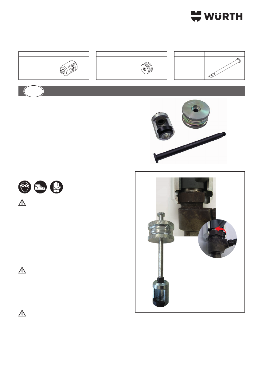
Das Kit erlaubt das Abziehen der Bosch Injektoren mit einem
Außenring zum Halten der elektrischen Anschlüsse mit einer
Schlüsselaufnahme von 29 mm und 30 mm.
VORBEREITUNG
DE
GB
FR
NL
ES
IT
PT
PL
DA
EL
1
a
3
Die Verankerung erfolgt unter dem Befestigungsring des elektrischen
Anschlusses am Injektor (Abb. 1).
Vermeidet die Önung/den Ausbau des Injektors, der nach der
Entfernung entsprechend intakt und unversehrt bleibt.
Die notwendige Ausziehkraft- und Bewegung wird mit Hilfe des
mitgelieferten Gleithammers erzeugt.
Auf Grund der eingesetzen Materialien sowie die Art und Weise
der Fertigung, können Zugkräfte bis zu einer Belastungsgrenze von
4,5to. aufgewendet werden.
WENN DER INJEKTOR NICHT HERAUSGEZOGEN
WIRD, DIE ANGEGEBENE MAXIMALE KRAFT NICHT
ÜBERSCHREITEN, SONDERN ANDERS VORGEHEN.
VERFAHREN
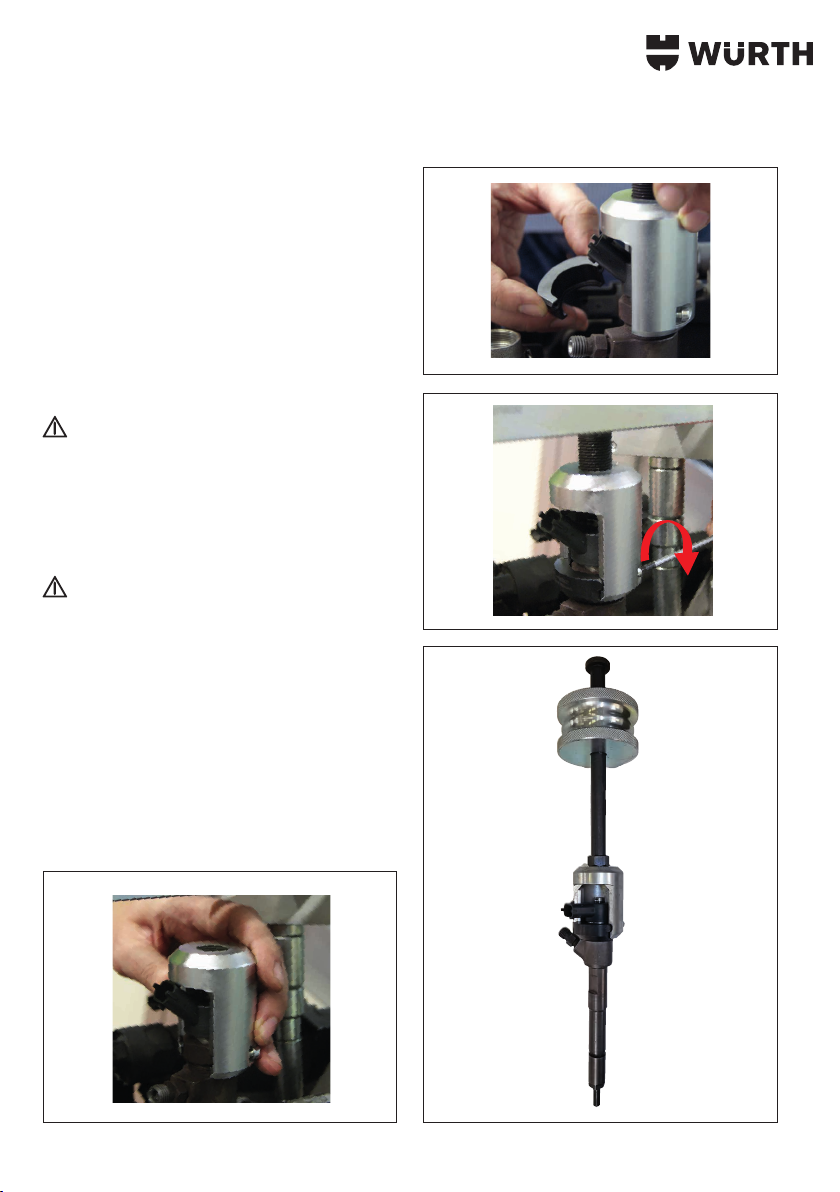
Positionieren Sie die Hülse am Injektor, sodass dieser unter dem Ring
erfasst wird (Abb. 2).
Lösen Sie den Befestigungsring gegebenenfalls
etwas, um den notwendigen Platz zur
Positionierung des Werkzeugs zu schaen (Abb.
1/a).
Koppeln Sie die die Einspannkomponente von der
gegenüberliegenden Seite der Hülse aus an (Abb. 3).
Befestigen Sie das so zusammengesetzte Werkzeug unter
Verwendung der mitgelieferten Schrauben (Abb. 4).
Den Injektor mit Hilfe des Gleithammers ausziehen (Abb. 5).
2
3
4
5

4
INTRODUCTION
Avant de commencer toute action, il est impératif de lire le présent
manuel d’utilisation.
La garantie du bon fonctionnement et la conformité des
performances du produit relèvent directement du respect de toutes
les instructions fournies dans le présent manuel.
La société garantit la conformité du produit aux spécications
techniques décrites dans le présent manuel.
Le producteur décline toute responsabilité pour tout usage impropre,
autre que les usages décrits.
Utiliser des gants anti-accident, des chaussures anti-accident, un
casque de protection et des lunettes de protection.
Usage impropre:
- Le produit ne doit être utilisé que pour l’usage prévu dans
la présente documentation. Tout autre usage doit être
considéré comme impropre.
- Le producteur décline toute responsabilité pour tout
dommage découlant d’usages erronés ou irraisonnables
de l’équipement.
- L’usage impropre annule la garantie.
Prendre bien soin des outils:
- Toujours garder les outils bien propres.
- Ranger les outils dans leur emballage d’origine.
AVERTISSEMENTS
Le fonctionnement du kit est réservé à du
personnel expert.
Le kit permet l’extraction d’injecteurs Bosch ayant une bague externe
d’étanchéité des connecteurs électriques avec une prise de clef de
29 mm et 30 mm.
L’ancrage se fait sous la bague de xation de la connexion
électrique à l’injecteur (g. 1).
PRÉPARATION
DE
GB
FR
NL
ES
IT
PT
PL
DA
EL
1
a

5
Evite l’ouverture / le démontage de l’injecteur, qui reste donc intact
après l’enlèvement.
La poussée nécessaire à l’extraction est exercée soit manuellement,
soit au moyen d’un vérin hydraulique.
Les matériaux utilisés et leurs traitements permettent d’atteindre une
poussée de 4 - 4,5 tonnes.
SI L'INJECTEUR NE S'EXTRAIT PAS, NE PAS
DÉPASSER LA FORCE MAXIMALE INDIQUÉE, MAIS
AGIR DIFFÉREMMENT.
PROCEDURE
Placer la douille sur l’injecteur de façon à le saisir sous la bague
(g. 2).
Si nécessaire, dévisser légèrement la bague de
xation de façon à créer l’espace nécessaire pour
placer l’outil (g. 1/a).
Accoupler du côté opposé de la douille le composant de blocage
(g. 3).
Fixer l’outil ainsi composé en utilisant les vis fournies (g. 4).
Enlever l’injecteur en utilisant la masse battante (g. 5).
2
3
4
5
6
INTRODUCCIÓN
Antes de realizar cualquier operación, es obligatorio leer el presente
manual de instrucciones.
La garantía de correcto funcionamiento y de plena conformidad de
las prestaciones del producto depende de la aplicación de todas las
instrucciones contenidas en este manual.
Se garantiza la conformidad del producto con las especicaciones
técnicas descritas en este manual. Cualquier uso impropio o
diferente de los descritos no es responsabilidad del fabricante.
Utilice guantes de protección, calzado de protección, casco y gafas
de protección.
Uso impropio:
- El producto se debe destinar exclusivamente al uso
descrito en esta documentación. Cualquier otro uso se
debe considerar impropio.
- El productor declina toda responsabilidad por eventuales
daños causados por usos erróneos o irracionales de la
herramienta.
- Además, el uso impropio invalida la garantía.
Conserve las herramientas con cuidado:
- Conserve siempre las herramientas limpias.
- Guarde las herramientas en sus embalajes originales.
ADVERTENCIAS
El kit debe ser utilizado exclusivamente por
personal experto.
El kit permite la extracción de inyectores Bosch con tuerca externa
de sujeción para los conectores eléctricos de 29 mm y 30 mm.
La sujeción se realiza por debajo de la tuerca de jación de la
conexión eléctrica al inyector (g. 1).
PROCEDURA
DE
GB
FR
NL
ES
IT
PT
PL
DA
EL
1
a

7
Evita la apertura/desmontaje del inyector, que permanece intacto e
íntegro después de la extracción.
El empuje necesario para la extracción se ejerce manualmente o con
un cilindro hidráulico.
Los materiales y tratamientos utilizados permiten alcanzar un empuje
de 4 - 4.5 toneladas.
SI EL INYECTOR NO SE EXTRAE, NO SUPERE LA
FUERZA MÁXIMA INDICADA Y ACTÚE DE MODO
DIFERENTE.
PROCEDIMIENTO
Coloque el casquillo en el inyector, sujetándolo por debajo de la
tuerca (g. 2).
Si es necesario, desenrosque ligeramente la
tuerca de jación con el objetivo de crear el
espacio necesario para colocar la herramienta
(g. 1/a).
Acople el elemento de bloqueo en el lado opuesto del casquillo
(g. 3).
Fije la herramienta así compuesta, utilizando los tornillos
suministrados (g. 4).
Extraer el inyector utilizando el blowback (g. 5).
2
3
4
5

8
INTRODUCTION
It is compulsory to read this instruction manual before starting any
kind of action.
The proper operation and full compliance of this product's
performance is guaranteed only if all the instructions provided in this
manual are closely adhered to.
We guarantee that this product complies with the technical
specications described in this manual.
The manufacturer shall not be held responsible for any improper uses
other than those described herein.
Use protective work gloves, protective footwear, hard hat and safety
goggles.
Misuse:
- This product should only be used as described in this
documentation; any other use is considered improper.
- The manufacturer accepts no responsibility for any
damage caused by the incorrect or unreasonable use of
the equipment.
- Moreover, misuse shall also void the warranty.
Take care of your tools:
- Be sure to store your tools in a clean state.
- Place the tools inside their original package.
WARNINGS
This tool set should be used by experienced
personnel only.
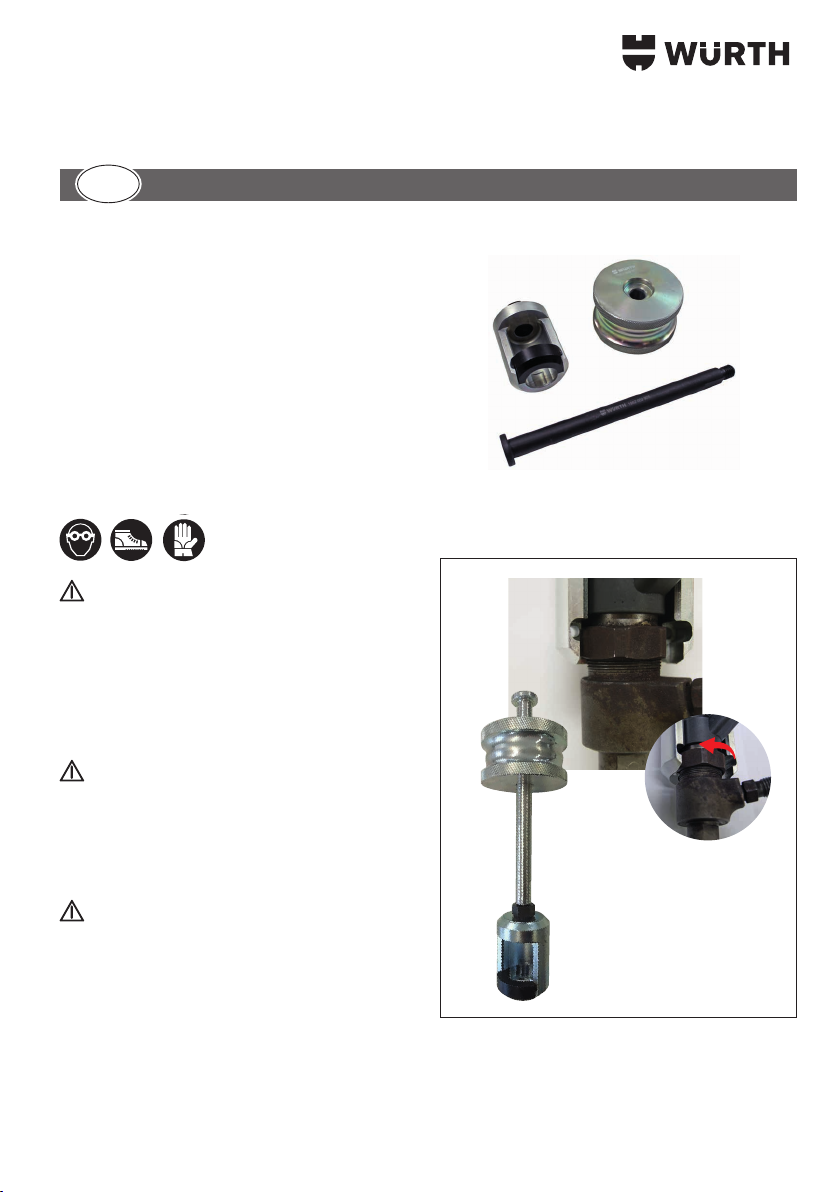
This tool set is to be used to remove Bosch injectors, which have an
outer ring that withholds the electrical connectors, by means of a 29
mm and 30 mm wrench grip.
Anchoring takes place underneath the locking ring of the injector's
electrical connection (g. 1).
METHOD OF PREPARATION
DE
GB
FR
NL
ES
IT
PT
PL
DA
EL
1
a

9
This avoids the opening/removal of the injector, which therefore
remains intact and undamaged after removal.
The thrust required to remove the injectors is applied either
manually or by means of the hydraulic cylinder.
Thanks to the materials used, along with their treatments, they can
reach a thrust of 4 to 4.5 tons
FOR PROBLEMS EXTRACTING THE INJECTOR
UNIT, DO NOT EXCEED THE MAXIMUM
FORCE INDICATED AND ADOPT A DIFFERENT
APPROACH.
PROCEDURE
Place the socket on the injector in order to grasp it under the ring
nut (g. 2).
If necessary, slightly unscrew the xing ring so
as to create the space needed to position the
tool (g 1/a).
Couple the locking component (g. 3) on the side opposite the
socket.
Secure the tool, assembled as described above, using the screws
provided (g. 4).
Remove the injector by using the slide hammer (g. 5).
2
3
4
5

10
PREMESSA
Prima di iniziare qualsiasi azione operativa è obbligatorio leggere il
presente manuale di istruzioni.
La garanzia del buon funzionamento e la piena rispondenza
prestazionale del prodotto è strettamente dipendente
dall’applicazione di tutte le istruzioni contenute in questo manuale.
Si garantisce la conformità del prodotto alle speciche tecniche
descritte in questo manuale. Usi impropri diversi da quelli descritti,
non sono di responsabilità del produttore.
Utilizzare guanti antinfortunistici, scarpe antinfortunistiche, elmetto e
occhiali di protezione.
Uso improprio:
- Il prodotto deve essere destinato solo ed esclusivamente
all'uso descritto in questa documentazione, ogni altro uso
è da considerarsi improprio.
- Il produttore declina ogni responsabilità per possibili
danni causati da usi errati o irragionevoli dell'attrezzatura.
- L’uso improprio invalida inoltre la garanzia.
Tenere gli attrezzi con cura:
- Conservare sempre gli attrezzi puliti.
- Riporre gli attrezzi all’interno della confezione originale.
AVVERTENZE
Il funzionamento del kit è riservato a personale
esperto.
Il kit permette l’estrazione di iniettori Bosch che hanno una ghiera
esterna di tenuta dei connettori elettrici con una presa di chiave di
29mm e 30mm.
L'ancoraggio avviene sotto la ghiera di ssaggio della connessione
elettrica all'iniettore (g. 1).
PROCEDURA
DE
GB
FR
NL
ES
IT
PT
PL
DA
EL
1
a
Table of contents
Languages:
Other Würth Tools manuals

Würth
Würth IVT PRINETO RSZ User manual

Würth
Würth master EH 4 User manual

Würth
Würth DIESEL DRAWER N.3 Quick guide

Würth
Würth master BS 14-A solid User manual

Würth
Würth CH 5-SE Quick guide

Würth
Würth 1952 006 505 Quick guide

Würth
Würth BST 350 User manual

Würth
Würth DSA 11 User manual

Würth
Würth master EMS 1.6 User manual

Würth
Würth DSF 10 Quick guide

Würth
Würth DSA 8-S Quick guide

Würth
Würth 1952 003 370 User manual

Würth
Würth BMH 45-XE User manual

Würth
Würth 1952 006 800 User manual

Würth
Würth 0891 110 500 Quick guide

Würth
Würth DIGA CS-3 User manual

Würth
Würth FP 12-A Quick guide

Würth
Würth 0714 58 229 User manual

Würth
Würth AKP 18-A-600 User manual

Würth
Würth 1952 006 765 Quick guide


