Westfalia 81 61 72 User manual
Other Westfalia Tools Storage manuals

Westfalia
Westfalia 94 53 56 User manual

Westfalia
Westfalia NST-S-16 User manual

Westfalia
Westfalia 85 84 42 User manual

Westfalia
Westfalia HN2 User manual

Westfalia
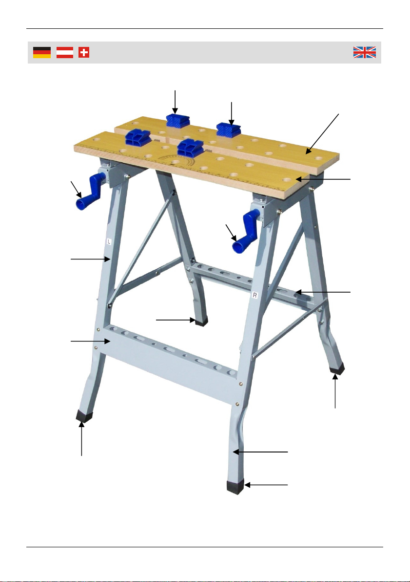
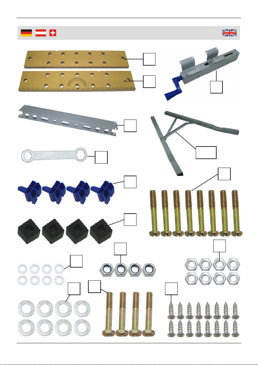
Westfalia 816172 User manual

Westfalia
Westfalia 812391 Installation guide

Westfalia
Westfalia 81 19 62 User manual

Westfalia
Westfalia 94 53 56 User manual

Westfalia
Westfalia 85 95 28 User manual

Westfalia
Westfalia 839530 User manual


Popular Tools Storage manuals by other brands

Ryobi
Ryobi RWB03 Original instructions

Husky
Husky H27CH5TR4BGK Use and care guide

Scheppach
Scheppach ts 2100 Translation from original manual

DIVERSIFIED WOODCRAFTS
DIVERSIFIED WOODCRAFTS SHAIN GSB-6024 Assembly instruction

Cassese
Cassese CS200 CART user & parts manual

Cornwell Tools
Cornwell Tools CTB360AKBK Assembly instructions

Kendall Howard
Kendall Howard ESDW-9630-1000 owner's manual

Lista
Lista Align Instructions for assembly

Workzone
Workzone 99609 Assembly instructions

Stanley
Stanley STST83800-1 instruction manual

Homak
Homak PROFESSIONAL Series Owner's manual & operating instructions

Perel
Perel ROLLER SHUTTER STORAGE CABINET Assembly instructions