WIKA CEP6100 User manual

Operating instructions
Betriebsanleitung
EN
DE
Documenting multi-function calibrator, model CEP6100
Dokumentierender Multifunktionskalibrator, Typ CEP6100
Documenting multi-function calibrator, model CEP6100

2
14120028.01 04/2015 EN/DE
WIKA operating instructions model CEP6100
EN
DE
Operating instructions model CEP6100 Page 3 - 68
Betriebsanleitung Typ CEP6100 Seite 69 - 135
© 2015 WIKA Alexander Wiegand SE & Co. KG
All rights reserved. / Alle Rechte vorbehalten.
WIKA®is a registered trademark in various countries.
WIKA®ist eine geschützte Marke in verschiedenen Ländern.
Prior to starting any work, read the operating instructions!
Keep for later use!
Vor Beginn aller Arbeiten Betriebsanleitung lesen!
Zum späteren Gebrauch aufbewahren!

3
WIKA operating instructions model CEP6100
14120028.01 04/2015 EN/DE
EN
Contents
Contents
1. General information 5
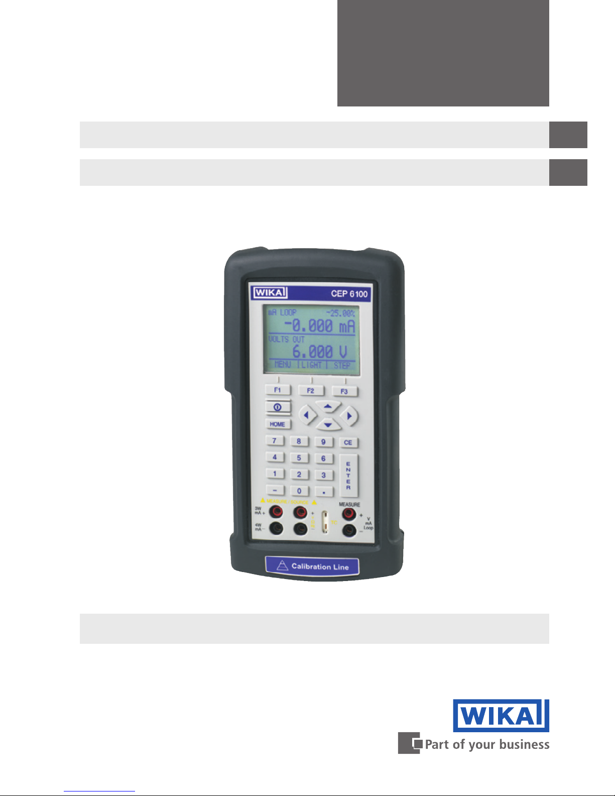
2. Short overview 6
2.1 Overview . . . . . . . . . . . . . . . . . . . . . . . . 6
2.2 Description . . . . . . . . . . . . . . . . . . . . . . . . 7
2.3 Scope of delivery . . . . . . . . . . . . . . . . . . . . . . 7
3. Safety 8
3.1 Explanation of symbols. . . . . . . . . . . . . . . . . . . . 8
3.2 Intended use . . . . . . . . . . . . . . . . . . . . . . . 8
3.3 Improper use . . . . . . . . . . . . . . . . . . . . . . . 9
3.4 Responsibility of the operator. . . . . . . . . . . . . . . . . . 9
3.5 Personnel qualification . . . . . . . . . . . . . . . . . . . . 10
3.6 Labelling, safety marks . . . . . . . . . . . . . . . . . . . . 10
4. Design and function 11
4.1 Front foil . . . . . . . . . . . . . . . . . . . . . . . . . 11
4.1.1 Connections . . . . . . . . . . . . . . . . . . . . . . 12
4.1.2 Key function . . . . . . . . . . . . . . . . . . . . . . 13
4.2 Batteries. . . . . . . . . . . . . . . . . . . . . . . . . 14
4.2.1 Selecting the batteries or rechargeable batteries . . . . . . . . . 14
4.2.2 Using the power supply unit . . . . . . . . . . . . . . . . 14
5. Transport, packaging and storage 15
5.1 Transport . . . . . . . . . . . . . . . . . . . . . . . . 15
5.2 Packaging and storage . . . . . . . . . . . . . . . . . . . . 15
6. Commissioning, operation 16
6.1 Main display . . . . . . . . . . . . . . . . . . . . . . . 17
6.2 Menu bar . . . . . . . . . . . . . . . . . . . . . . . . 18
6.2.1 “Measuring” menu function . . . . . . . . . . . . . . . . . 18
6.2.2 “Output” menu function . . . . . . . . . . . . . . . . . . 19
6.2.3 “Pulse output” menu function . . . . . . . . . . . . . . . . 19
6.2.4 “UPPER”, “LOWER” and “MORE” menu function . . . . . . . . . 19
6.2.5 “Documentation” menu function . . . . . . . . . . . . . . . 20
6.2.6 “Automatic output function” menu function. . . . . . . . . . . . 20
6.2.7 “Frequency or pulse output” menu function . . . . . . . . . . . 20
6.2.8 “Contrast” menu function . . . . . . . . . . . . . . . . . 20
6.2.9 “Automatic switch-off” menu function . . . . . . . . . . . . . 21
6.2.10 “Time” menu function . . . . . . . . . . . . . . . . . . . 21
6.2.11 “Probe-specific coefficients” menu function . . . . . . . . . . . 21
6.2.12 “ZERO” menu function . . . . . . . . . . . . . . . . . . 22
6.2.13 “Terminal emulation” menu function . . . . . . . . . . . . . . 22
6.2.14 “Parameter selection” menu function . . . . . . . . . . . . . 22
6.3 Cursor control/set-point control . . . . . . . . . . . . . . . . . 22
6.4 Using the measuring modes (lower display) . . . . . . . . . . . . . 23

4
WIKA operating instructions model CEP6100
14120028.01 04/2015 EN/DE
EN
Contents
Declarations of conformity can be found online at www.wika.com.
6.4.1 Measuring voltage and frequency . . . . . . . . . . . . . . 23
6.4.2 Measuring current (mA) . . . . . . . . . . . . . . . . . . 23
6.4.3 Measuring temperature . . . . . . . . . . . . . . . . . . 24
6.4.4 Measuring pressure . . . . . . . . . . . . . . . . . . . 26
6.5 Using the output modes (lower display) . . . . . . . . . . . . . . 28
6.5.1 Setting the output parameters 0 % and 100 % . . . . . . . . . . 28
6.5.2 Using the automatic output functions . . . . . . . . . . . . . 28
6.5.3 Current output . . . . . . . . . . . . . . . . . . . . . 29
6.5.4 Simulating a transmitter . . . . . . . . . . . . . . . . . . 30
6.5.5 Voltage output . . . . . . . . . . . . . . . . . . . . . 31
6.5.6 Frequency output . . . . . . . . . . . . . . . . . . . . 31
6.5.7 Pulse output . . . . . . . . . . . . . . . . . . . . . . 31
6.5.8 Simulating thermocouples . . . . . . . . . . . . . . . . . 32
6.5.9 Simulating resistance or resistance thermometers . . . . . . . . . 32
6.6 Using the isolated measuring modes (upper display). . . . . . . . . . 34
6.6.1 Measuring voltage (V) or current (mA) . . . . . . . . . . . . . 34
6.6.2 Measuring current with DC 24 V voltage supply . . . . . . . . . . 35
6.7 Using the upper and lower displays for test and calibration. . . . . . . . 35
6.7.1 Calibrating a display instrument . . . . . . . . . . . . . . . 35
6.7.2 Calibrating an I/P instrument . . . . . . . . . . . . . . . . 36
6.7.3 Calibrating a transmitter . . . . . . . . . . . . . . . . . . 37
6.7.4 Calibrating a pressure transmitter. . . . . . . . . . . . . . . 38
7. Document mode 38
7.1 Introduction. . . . . . . . . . . . . . . . . . . . . . . . 38
7.2 New tag “AS FOUND” test . . . . . . . . . . . . . . . . . . . 49
7.2.1 Setup . . . . . . . . . . . . . . . . . . . . . . . . 49
8. CalLOG programme 54
8.1 System requirements . . . . . . . . . . . . . . . . . . . . 54
8.2 Installation . . . . . . . . . . . . . . . . . . . . . . . . 54
8.3 Overview . . . . . . . . . . . . . . . . . . . . . . . . 54
9. Faults 55
10. Maintenance, cleaning and recalibration 56
10.1 Maintenance . . . . . . . . . . . . . . . . . . . . . . . 56
10.2 Cleaning. . . . . . . . . . . . . . . . . . . . . . . . . 56
10.3 Recalibration . . . . . . . . . . . . . . . . . . . . . . . 57
11. Dismounting, return and disposal 57
11.1 Dismounting . . . . . . . . . . . . . . . . . . . . . . . 57
11.2 Return . . . . . . . . . . . . . . . . . . . . . . . . . 57
11.3 Disposal . . . . . . . . . . . . . . . . . . . . . . . . . 58
12. Specifications 59
13. Accessories 66
Appendix: EC declaration of conformity 67

5
WIKA operating instructions model CEP6100
14120028.01 04/2015 EN/DE
EN
1. General information
■
The model CEP6100 documenting multi-function calibrator described in these
operating instructions has been manufactured using state-of-the-art technology.
All components are subject to stringent quality and environmental criteria during
production. Our management systems are certified to ISO 9001 and ISO 14001.
■
These operating instructions contain important information on handling the instrument.
Working safely requires that all safety instructions and work instructions are observed.
■
Observe the relevant local accident prevention regulations and general safety
regulations for the instrument’s range of use.
■
The operating instructions are part of the product and must be kept in the immediate
vicinity of the instrument and readily accessible to skilled personnel at any time. Pass
the operating instructions onto the next operator or owner of the instrument.
■
Skilled personnel must have carefully read and understood the operating instructions
prior to beginning any work.
■
The general terms and conditions contained in the sales documentation shall apply.
■
Subject to technical modifications.
■
Factory calibrations / DKD/DAkkS calibrations are carried out in accordance with
international standards.
■
Further information:
- Internet address: www.wika.de / www.wika.com
- Relevant data sheet: CT 83.51
- Application consultant: Tel.: +49 9372 132-5049
Fax: +49 9372 132-8005049
CTSer[email protected]
1. General information

6
WIKA operating instructions model CEP6100
14120028.01 04/2015 EN/DE
EN
1
2
3
1. General information / 2. Short overview
Abbreviations, definitions
RTD Resistance thermometer
TC Thermocouple
2W 2-wire measurement
Two test cables are used for the voltage supply.
The measurement signal also provides the supply current.
3W 3-wire measurement
Two test cables are used for the voltage supply.
One test cable is used for the measurement signal.
4W 4-wire measurement
Two test cables are used for the voltage supply.
Two test cables are used for the measurement signal.
CJC Cold junction compensation
2. Short overview
2.1 Overview
Display
Keypad
Connections
1
2
3

7
WIKA operating instructions model CEP6100
14120028.01 04/2015 EN/DE
EN
2. Short overview
2.2 Description
The model CEP6100 documenting multi-function calibrator is a battery-operated hand-
held instrument which can measure or simulate electrical parameters.
The model CEP6100 works with different thermocouples and resistance thermometers,
among others.
Very high accuracy and diverse special functions make the instrument a user-friendly and
highly flexible calibration instrument.
2.3 Scope of delivery
■
Documenting multi-function calibrator model CEP6100
■
Operating instructions
■
Test cables, three sets (red/black)
■
3.1 calibration certificate per DIN EN 10204
■
Four AA batteries
■
Protective rubber boot
■
RS-232 interface cable
■
USB serial adapter
■
CalLOG software
■
Quick start guide
Cross-check scope of delivery with delivery note.

8
WIKA operating instructions model CEP6100
14120028.01 04/2015 EN/DE
EN
3. Safety
3. Safety
3.1 Explanation of symbols
WARNING!
... indicates a potentially dangerous situation that can result in serious
injury or death, if not avoided.
CAUTION!
... indicates a potentially dangerous situation that can result in light injuries
or damage to equipment or the environment, if not avoided.
DANGER!
... identifies hazards caused by electrical power. Should the safety instruc-
tions not be observed, there is a risk of serious or fatal injury.
Information
... points out useful tips, recommendations and information for efficient
and trouble-free operation.
3.2 Intended use
The model CEP6100 documenting multi-function calibrator is a battery-operated hand-
held instrument which can measure and output/simulate current, voltage, resistance,
RTD’s, TC’s, frequency and pulses.
In addition, external pressure sensors/pressure modules can be connected which enable
pressure to measure with this calibrator. The WIKA model CPT6600 pressure modules
and the Mensor model CPT6100/CPT6180 precision pressure sensors are compatible
here.
This instrument is not permitted to be used in hazardous areas!
The instrument has been designed and built solely for the intended use described here,
and may only be used accordingly.
The technical specifications contained in these operating instructions must be observed.
Improper handling or operation of the instrument outside of its technical specifications
requires the instrument to be taken out of service immediately and inspected by an
authorised WIKA service engineer.

9
WIKA operating instructions model CEP6100
14120028.01 04/2015 EN/DE
EN
Handle electronic precision measuring instruments with the required care (protect from
humidity, impacts, strong magnetic fields, static electricity and extreme temperatures,
do not insert any objects into the instrument or its openings). Plugs and sockets must be
protected from contamination.
The manufacturer shall not be liable for claims of any type based on operation contrary to
the intended use.
3.3 Improper use
WARNING!
Injuries through improper use
Improper use of the instrument can lead to hazardous situations and
injuries.
▶
Refrain from unauthorised modifications to the instrument.
▶
Do not use the instrument within hazardous areas.
▶
Only use accessories provided by WIKA.
Any use beyond or different to the intended use is considered as improper use.
Do not use this instrument in safety or emergency stop devices.
3.4 Responsibility of the operator
The instrument is used in the industrial sector.The operator is therefore responsible for
legal obligations regarding safety at work.
The safety instructions within these operating instructions, as well as the safety, accident
prevention and environmental protection regulations for the application area must be
maintained.
3. Safety

10
WIKA operating instructions model CEP6100
14120028.01 04/2015 EN/DE
EN
3.5 Personnel qualification
WARNING!
Risk of injury should qualification be insufficient
Improper handling can result in considerable injury and damage to equip-
ment.
▶
The activities described in these operating instructions may only be
carried out by skilled personnel who have the qualifications described
below.
Skilled personnel
Skilled personnel, authorised by the operator, are understood to be personnel who,
based on their technical training, knowledge of measurement and control technology and
on their experience and knowledge of country-specific regulations, current standards and
directives, are capable of carrying out the work described and independently recognising
potential hazards.
Special operating conditions require further appropriate knowledge, e.g. of aggressive
media.
3.6 Labelling, safety marks
Product label
The product label is located on the side of the instrument beneath the protective rubber
boot.
Binary code
Serial no.
3. Safety

11
WIKA operating instructions model CEP6100
14120028.01 04/2015 EN/DE
EN
Symbols
Before commissioning the instrument, ensure you read the operating
instructions!
Instruments bearing this mark comply with the relevant European direc-
tives.
This marking on the instruments indicates that they must not be disposed
of in domestic waste.The disposal is carried out by return to the manufac-
turer or by the corresponding municipal authorities (see EU directive
2002/96/EC).
3. Safety / 4. Design and function
4. Design and function
The model CEP6100 documenting multi-function calibrator is a battery-operated hand-
held instrument which can measure and output/simulate current, voltage, resistance,
RTD’s, TC’s, frequency and pulses.
In addition, external pressure sensors/pressure modules can be connected which enable
pressure to measure with this calibrator. The WIKA model CPT6600 pressure modules
and the Mensor model CPT6100/CPT6180 precision pressure sensors are compatible
here.
4.1 Front foil
The following figures show the location of the input and output terminals and also the
positions of the buttons on the calibrator.

12
WIKA operating instructions model CEP6100
14120028.01 04/2015 EN/DE
EN
F1
HOME
7
F2 F3
89CE
E
N
T
E
R
4
1
MEASURE / SOURCE
3W
mA+ TC V
mA
Loop
+
V
Hz
–
+
–
5
2
0
6
3
.
4W
mA–
MEASURE
–
CEP6100
Ω
1
2
3
4
6
8
9
7 5
4.1.1 Connections
4. Design and function
1Connection for external pressure module
Connects the calibrator with a pressure module for pressure measurement.
2Serial interface
Connects the calibrator with a PC for remote operation.
3+ 4(Isolated) Current and voltage input as well as for output of DC 24 V voltage
supply
Terminals for the measurement of current, voltage and separate current loop supplies.
5Thermocouple input/output
Terminal for the measurement or simulation of thermocouples. Suitable for polarised
miniature connectors for thermocouples.
6+ 7Voltage, resistance thermometers (2-wire), frequency, pulse, input/output
Terminals for the simulation and measurement of voltage, frequency, pulse trains and
resistance thermometers (RTDs).
8+ 9Current, resistance thermometers (3-wire, 4-wire), input/output
Terminals for the simulation and measurement of current and also for resistance
thermometer measurements with 3- and 4-wire connection.

13
WIKA operating instructions model CEP6100
14120028.01 04/2015 EN/DE
EN
F1
HOME
7
F2 F3
89CE
E
N
T
E
R
4
1
MEASURE / SOURCE
3W
mA+ TC V
mA
Loop
+
V
Hz
–
+
–
5
2
0
6
3
.
4W
mA–
MEASURE
–
CEP6100
Ω
1
2
3
4
6
8
7
5
4.1.2 Key function
4. Design and function
1Display
2Function keys, used to operate the menu bar at the bottom of the calibrator display
The [F1] key acts to select the options in the left-hand box, the [F2] key acts for the selection of
the functions in the middle box and the [F3] key for the selection of the functions in the right-
hand box.
3Modification of individual digits of the output value; increase, decrease or ramp output
value
Use the left and right arrow buttons to select which digit in the output value should be changed.
With the up and down arrow keys, the output value can be increased, decreased or changed to
a ramp form.
4Clear the input value
The last numerical value input will be deleted.
5ENTER
Confirms the input of numerical values.
6Numeric keys
Used for the input of numerical values.
7HOME, returns to main menu
Reverts back to the start menu on the menu bar.
8ON/OFF
Switches the calibrator on and off.

14
WIKA operating instructions model CEP6100
14120028.01 04/2015 EN/DE
EN
4.2 Batteries
4.2.1 Selecting the batteries or rechargeable batteries
The model CEP6100 works with four alkaline batteries (AA) or with four NiMH
rechargeable batteries (AA).
4.2.2 Using the power supply unit
CAUTION!
Physical injuries and damage to property and the environment
If alkaline batteries are used in the model CEP6100 documenting multi-
function calibrator, when the power supply unit is used at the same time,
overheating, severe damage and leakage can occur. Leakage of electro-
lyte from batteries presents a significant health risk.
▶
Only ever use the power supply unit without batteries or with NiMH
rechargeable batteries in the instrument.
▶
Only use undamaged and fault-free power supply units.
▶
Use WIKA accessories.
Using the power supply unit:
1. Remove alkaline batteries from the model CEP6100 or insert rechargeable batteries
in the calibrator’s compartments.
2. Connect the power supply unit to the calibrator.
3. Insert the power cord into the power connector.
Ensure that the correct power supply is present when doing this.
The NiMH rechargeable batteries in the instrument are recharged slowly.
Recharging takes between approx. 10 and 12 hours.
4. After use, disconnect the power cord from the mains and the calibrator.
4. Design and function

15
WIKA operating instructions model CEP6100
14120028.01 04/2015 EN/DE
EN
5. Transport, packaging and storage
5.1 Transport
Check the model CEP6100 documenting multi-function calibrator for any damage that
may have been caused by transport.
Obvious damage must be reported immediately.
CAUTION!
Damage through improper transport
With improper transport, a high level of damage to property can occur.
▶
When unloading packed goods upon delivery as well as during
internal transport, proceed carefully and observe the symbols on the
packaging.
▶
With internal transport, observe the instructions in chapter 5.2 “Packag-
ing and storage”.
If the instrument is transported from a cold into a warm environment, the formation of
condensation may result in instrument malfunction. Before putting it back into operation,
wait for the instrument temperature and the room temperature to equalise.
5.2 Packaging and storage
Do not remove packaging until just before use.
Keep the packaging as it will provide optimum protection during transport (e.g. change in
place of use, sending for repair).
Permissible conditions at the place of storage:
■
Storage temperature: -20 ... +60 °C
■
Humidity: 0 ... 90 % relative humidity (non-condensing)
Avoid exposure to the following factors:
■
Direct sunlight or proximity to hot objects
■
Mechanical vibration, mechanical shock (putting it down hard)
■
Soot, vapour, dust and corrosive gases
■
Hazardous environments, flammable atmospheres

16
WIKA operating instructions model CEP6100
14120028.01 04/2015 EN/DE
EN
5. Transport, packaging and storage / 6. Commissioning, ...
Store the model CEP6100 documenting multi-function calibrator in its original packaging
in a location that fulfils the conditions listed above. If the original packaging is not
available, pack and store the instrument as described below:
1. Wrap the instrument in an antistatic plastic film.
2. Place the instrument, along with shock-absorbent material, in the packaging.
3. If stored for a prolonged period of time (more than 30 days), place a bag containing a
desiccant inside the packaging.
6. Commissioning, operation
ATTENTION!
Damage through electric shock
Higher voltages than the rated voltage can cause damage to the model
CEP6100 documenting multi-function calibrator. With any damage to the
case or the test cables, an electric shock can result from any contact.
▶
Apply the correct rated voltage, see chapter 10 “Specifications”.
▶
Do not use the calibrator if it is damaged. Prior to use check the case of
the calibrator. Pay attention to missing plastic components and cracks,
in particular to the insulation around the connections.
▶
Do not use the calibrator in case of malfunction.The instrument
protection might be compromised. In case of doubt, have the calibrator
checked.
▶
The battery compartment must be closed and sealed.
▶
Change the batteries as soon as the battery symbol is displayed.
▶
Always use the correct connector sockets, functions and measuring
ranges for the measurement or simulation.
▶
Only open the battery compartment once all cable connections have
been disconnected from the calibrator.
▶
Check the test cables for damaged insulation or bare metal compo-
nents.Test the continuity of the test cables. Replace any damaged test
cable before using the calibrator.
▶
Do not touch the metal parts at the test cables.
As soon as the model CEP6100 documenting multi-function calibrator is turned on, by
pressing the ON/OFF key, it will go through a short self-test routine. During this routine,
the display shows the current firmware version and the auto-shutdown status.
The calibrator requires a maximum of 5 minutes warm-up to reach its specified accuracy.
Large changes in ambient temperature may make a longer warm-up period necessary.

17
WIKA operating instructions model CEP6100
14120028.01 04/2015 EN/DE
EN
6. Commissioning, operation
6.1 Main display
The display of the model CEP6100 documenting multi-function calibrator is subdivided
into 3 main sections: the upper display, the lower display and the menu bar.
■
The upper display is used for the measurement of direct current voltages, direct
current (with or without loop voltage) and for pressure measurement.
■
The lower display can be used both for measurement and for simulation.
■
The menu bar (at the bottom of the display) serves for configuration of the upper and
lower display (according to the desired function).
The following figure shows the location of the various display fields, which are described
in the table.
Numeric display
Displays the numeric value of the measured or simulated signal.
A measurement “OL” or “-OL” signals a value outside of the measuring range.
Display of the span
Only for the display “mA” and “mA LOOP”.
Displays the current measured value with respect to 4 mA = 0 % and 20 mA = 100 %.
Units
Displays the corresponding unit for measurement or output/simulation.
For “RTD” (resistance thermometer) and “TC” (thermocouple), °C or °F are offered; for
“FREQ” (frequency) and “PULSE” (pulse), CPM, Hz or kHz.
mA IN
0.000 mA
-25.00%
RTD IN 4W P10-385
MENU
-OL °C
LIGHT
2
3
4
7
6
5
1
1
2
3

18
WIKA operating instructions model CEP6100
14120028.01 04/2015 EN/DE
EN
6. Commissioning, operation
Sensor type
For measurements and simulation of various resistance thermometers (RTDs) and
thermocouples (TCs).
All possible sensor types are stated in the specifications (see chapter 10 “Specifica-
tions”).The options also show the amplitude of the pulse or frequency simulation and
the pressure unit.
Additional settings
Only available for the option “TC measurement” (thermocouple) and
“RTD measurement” (resistance thermometer).
With the option “TC”, this setting switches the cold junction compensation (CJC) on or
off.
With RTD measurements, this setting defines the number of wires for the
measurement (2W = 2-wire measurement, 3W = 3-wire measurement,
4W = 4-wire measurement).
Input/output display
Switches the lower display between input mode (measuring) and output mode
(output/simulation).
Primary parameters
Defines which parameter will be measured or outputted/simulated.
The available options for the upper display are: “VOLTS IN” (input voltage),
“PRESSURE” (pressure), “mA IN” (input current in mA) and “mA LOOP” (mA with
DC 24 V voltage supply).
The available options for the lower display are: “VOLTS” (voltage),
“TC” (thermocouple), “RTD” (resistance thermometer), “FREQ” (frequency),
“PULSE” (pulse), “PRESSURE” (pressure) and “mA” (current) or
“mA 2W SIM” (current simulation).
6.2 Menu bar
The display parameters are managed via the menu bar, which is found along the bottom
of the LC display.The function keys [F1], [F2] and [F3] enable navigation through all levels
and options of the menu bar.The upper menu level is the start menu.
One can return to this at any time with the [HOME] key.There are three variants of the
start menu: the input start menu, the output start menu and the pulse start menu.
6.2.1 “Measuring” menu function
In the start menu for the function “Measuring”, only the options “MENU” and “LIGHT” are
active. The option “MENU” calls the next menu level to the menu bar, i.e. to call the main
menu. Press the corresponding function key, [F1], to call the main menu.
4
5
6
7

19
WIKA operating instructions model CEP6100
14120028.01 04/2015 EN/DE
EN
6. Commissioning, operation
The option “LIGHT” switches on the backlight for the LC display. Press the corresponding
function key [F2] to switch on the backlighting.
6.2.2 “Output” menu function
In the start menu for the function “Output” there are three active options “MENU”, “LIGHT”
and “STEP” or “RAMP”.
The first two options work just like in the start menu. The third option can be selected
via the automatic output function menu option, and acts to switch on or off the selected
automatic function. For further information, see chapter 6.5.2 “Using the automatic output
functions”.The automatic output functions are stopped as soon as the menu is exited or
the [HOME] key is pressed.
6.2.3 “Pulse output” menu function
The pulse start menu also has three active options, “MENU”, “TRIG” and “COUNTS”.
The options “TRIG” and “COUNTS” are used for pulse simulation.The function of these
options is explained in chapter 6.5.7 “Pulse output”.
6.2.4 “UPPER”, “LOWER” and “MORE” menu function
The next level of the menu bar is the main menu itself. Which levels are available under
the main menu depends on the selected operating mode of the calibrator. The options are
“UPPER”, “LOWER” and “MORE”.
With “UPPER”, the selection menu for the parameters of the upper display will be called.
With “LOWER”, the selection menu for the parameters of the lower display will be called.
“MORE” switches to the next menu level.
MENU LIGHT
MENU LIGHT STEP
MENU TRIG
COUNTS
UPPER LOWER MORE

20
WIKA operating instructions model CEP6100
14120028.01 04/2015 EN/DE
EN
6.2.5 “Documentation” menu function
This “Documentation” menu level is used for saving calibrations.The options are
“DOCUMENT”, “NEXT” and “DONE”. By selecting “DOCUMENT”, one enters the
documentation menu.
“NEXT” switches to the next menu function and “DONE” returns to the start menu. For
further information, see chapter 7 “Document mode”.
6.2.6 “Automatic output function” menu function
The “Automatic output function” is a menu function in the “Output” mode and is called by
pressing “MORE”.The options are “AUTO FUNC”, “NEXT” and “DONE”.
With “AUTO FUNC” the parameters of the automatic output function can be set. “NEXT”
switches to the next menu function and “DONE” returns to the start menu. For further
information, see chapter 6.5.2 “Using the automatic output functions”.
6.2.7 “Frequency or pulse output” menu function
When the lower display is used for frequency or pulse outputs, in addition, the sub-menu
for frequency is displayed after the main menu.The options are “FREQ LEVEL”, “NEXT”
and “DONE”.
The option “FREQ LEVEL” enables the setting of the amplitude of the oscillation. “NEXT”
switches to the next menu function and “DONE” returns to the start menu.
6.2.8 “Contrast” menu function
The next menu level is the contrast menu.The options are “CONTRAST”, “NEXT” and
“DONE”.
The option “CONTRAST” acts to set the contrast. “NEXT” switches to the next menu
function and “DONE” returns to the start menu. The contrast can be set with the arrow
keys [F1, F2], which are displayed after selecting the option “CONTRAST”.
In certain cases, large changes in contrast can make the display difficult to read under
normal conditions. If the display is too bright or too dark for the values to be read, the
following steps should be taken in order to reset the contrast setting to the default.
DONENEXTDOCUMENT
AUTO FUNC
NEXT DONE
FREQ LEVEL
NEXT DONE
6. Commissioning, operation
Table of contents
Languages:
Other WIKA Test Equipment manuals

WIKA
WIKA CPH7000 User manual

WIKA
WIKA CPH8000-ET User manual

WIKA
WIKA CEP1500 User manual

WIKA
WIKA PG28 User manual

WIKA
WIKA DELTA-comb DPGS40TA User manual

WIKA
WIKA CTD9100-ZERO User manual

WIKA
WIKA CalibratorUnit CPU6000 Series User manual

WIKA
WIKA CalibratorUnit CPU6000 Series User manual

WIKA
WIKA CPB 5800 User manual

WIKA
WIKA CTD9350 User manual
Popular Test Equipment manuals by other brands

Fieldpiece
Fieldpiece MR45CAN Operator's manual

Cypress
Cypress CY3631 user guide

Druck
Druck DPI 620 Genii user manual

Good Will Instrument
Good Will Instrument PEL-2000B Series user manual

EXFO
EXFO MaxTester Max-610 Quick reference guide

System Sensor
System Sensor Zonecheck Installation and maintenance instructions