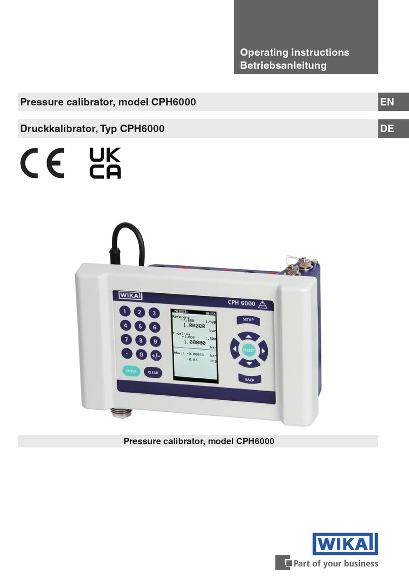
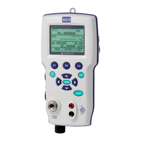
WIKA CPH65I0 User manual

Intrinsically safe hand-held pressure calibrator model CPH65I0 GB
Eigensicherer Hand-Held Druckkalibrator Typ CPH65I0 D
Intrinsically safe hand-held pressure calibrator model CPH65I0
Operating instructions
Betriebsanleitung

2 WIKA Operating Instruction, Model CPH65I0
GB
GB Operating instructions model CPH65I0 Page 1 - 40
D Betriebsanleitung Typ CPH65I0 Seite 41 - 80
© 2011 WIKA Alexander Wiegand SE & Co. KG
All rights reserved. / Alle Rechte vorbehalten.
WIKA® is a registered trademark in various countries.
WIKA® ist eine geschützte Marke in verschiedenen Ländern.
Prior to starting any work, read the operating instructions!
Keep for later use!
Vor Beginn aller Arbeiten Betriebsanleitung lesen!
Zum späteren Gebrauch aufbewahren!
14061681.01 11/2012 GB/D

Contents
WIKA Operating Instruction, Model CPH65I0 3
GB
C
C
Co
o
on
n
nt
t
te
e
en
n
nt
t
ts
s
s
1General Information.........................................................................................................5
2Safety..............................................................................................................................7
2.1 Intended use....................................................................................................................7
2.2 Personnel qualification.....................................................................................................8
2.3 Additional safety instructions for instruments with ATEX approval...................................8
2.4 Special hazards...............................................................................................................9
2.5 Labelling / safety marks.................................................................................................11
2.5.1 Product label .................................................................................................................11
2.5.2 Explanation of symbols..................................................................................................11
3Specifications ................................................................................................................12
4Design and Function......................................................................................................14
4.1 Short description / Description.......................................................................................14
4.2 Scope of delivery...........................................................................................................14
4.3 Pressure and electrical connections ..............................................................................15
4.4 Keypad..........................................................................................................................15
5Transport, packaging and storage .................................................................................16
5.1 Transport.......................................................................................................................16
5.2 Packaging......................................................................................................................16
5.3 Storage..........................................................................................................................16
6Commissioning, operation .............................................................................................17
6.1 Commissioning..............................................................................................................17
6.2 Calibrator display...........................................................................................................17
6.2.1 Main menu functionality.................................................................................................18
6.3 Using the backlighting....................................................................................................20
6.4 Using the "ZERO" function.............................................................................................20
6.4.1 Internal relative pressure sensor....................................................................................20
6.4.2 Internal absolute pressure sensor..................................................................................20
6.5 Other menu controlled functions....................................................................................21
6.5.1 Setting the contrast........................................................................................................21
6.5.2 Locking and unlocking configurations............................................................................21
6.5.3 Saving and recalling settings.........................................................................................22
6.5.4 Setting auto shut-off parameter .....................................................................................22
6.5.5 Activating and deactivating a display.............................................................................23
6.5.6 Low resolution function..................................................................................................23
6.5.7 Setting the resistance thermometer probe.....................................................................24
6.5.8 Damping / Average reading...........................................................................................24
6.6 Measuring pressure.......................................................................................................25
6.6.1 Media compatibility........................................................................................................25
6.7 Measuring current..........................................................................................................26
6.8 Measuring temperature with a resistance thermometer .................................................26
6.9 Performing a pressure switch test..................................................................................27
6.10 Calibrating transmitters..................................................................................................30
6.10.1 Using the mA measurement function.............................................................................30
6.10.2 Calibrating a pressure-to-current transmitter..................................................................30
6.10.3 “%-Error” function..........................................................................................................31
6.11 “MIN/MAX” value capture ..............................................................................................33
6.12 Factory settings.............................................................................................................34
6.13 Flow calibration..............................................................................................................35
7Maintenance, cleaning and servicing.............................................................................36
7.1 Maintenance..................................................................................................................36
7.2 Replacing batteries........................................................................................................36

4 WIKA Operating Instruction, Model CPH65I0
GB
7.3 Cleaning........................................................................................................................37
7.4 Recalibration .................................................................................................................37
8Dismounting, return and disposal ..................................................................................38
8.1 Dismounting ..................................................................................................................38
8.2 Return ...........................................................................................................................38
8.3 Disposal ........................................................................................................................38
Appendix 1: EC Declaration of Conformity for model CPH65I0.................................................39
Appendix 2: EC-type examination certificate for model CPH65I0..............................................40

1 General Information
WIKA Operating Instruction, Model CPH65I0 5
GB
1 General Information
■The CPH65I0 intrinsically safe hand-held pressure calibrator described in the operating
instructions has been manufactured using state-of-the-art technology.
All components are subject to stringent quality and environmental criteria during production. Our
management systems are certified to ISO 9001 and ISO 14001.
■These operating instructions contain important information on handling the CPH65I0 intrinsically
safe hand-held pressure calibrator. Working safely requires that all safety instructions and work
instructions are observed.
■Observe the relevant local accident prevention regulations and general safety regulations for the
range of use of the CPH65I0 intrinsically safe hand-held pressure calibrator.
■The operating instructions are part of the instrument and must be kept in the immediate vicinity
of the CPH65I0 intrinsically safe hand-held pressure calibrator and readily accessible to skilled
personnel at any time.
■Skilled personnel must have carefully read and understood the operating instructions, prior to
beginning any work.
■The manufacturer's liability is void in the case of any damage caused by using the product
contrary to its intended use, non-compliance with these operating instructions, assignment of
insufficiently qualified skilled personnel or unauthorised modifications to the CPH65I0
intrinsically safe hand-held pressure calibrator.
■The general terms and conditions, contained in the sales documentation, shall apply.
■Subject to technical modifications.
■Factory calibrations / DKD/DAkkS calibrations are carried out in accordance with international
standards.
■Further information:
- Internet address: www.wika.de / www.wika.com
- Relevant Data Sheet: CT 14.51
- Application consultant: Tel.: (+49) 9372/132-9986
Fax: (+49) 9372/132-8767
E-Mail:[email protected]

1 General Inforamtion
6 WIKA Operating Instruction, Model CPH65I0
GB
Explanation of symbols
WARNING!
... indicates a potentially dangerous situation, which can result in serious
injury or death, if not avoided.
CAUTION!
... indicates a potentially dangerous situation, which can result in light
injuries or damage to equipment or the environment, if not avoided.
Information
... points out useful tips, recommendations and information for efficient and
trouble-free operation.
DANGER!
...identifies hazards caused by electric power. Should the safety instructions
not be observed, there is a risk of serious or fatal injury.
WARNING!
... indicates a potentially dangerous situation in a potentially explosive
atmosphere, resulting in serious injury or death, if not avoided.

2 Safety
WIKA Operating Instruction, Model CPH65I0 7
GB
2 Safety
WARNING!
Before installation, commissioning and operation, ensure that the appropriate
CPH65I0 intrinsically safe hand-held pressure calibrator has been selected in terms
of measuring range, design and specific measuring conditions. Serious injuries
and/or damage can occur should these not be observed.
Further important safety instructions can be found in the individual chapters of these
operating instructions.
2.1 Intended use
The CPH65I0 intrinsically safe hand-held pressure calibrator can be used as a calibration
instrument and also for any application which requires accuracy pressure measurement.
The CPH65I0 intrinsically safe hand-held pressure calibrator has been designed and built solely for
the intended use described here, and may only be used accordingly.
The technical specifications contained in these operating instructions must be observed.
Improper handling or operation of the CPH65I0 intrinsically safe hand-held pressure calibrator
outside of its technical specifications requires the instrument to be shut down immediately and
inspected by an authorised WIKA service engineer.
Handle electronic precision measuring instruments with the required care (protect from humidity,
impacts, strong magnetic fields, static electricity and extreme temperatures, do not insert any
objects into the instrument or its openings). Plugs and sockets must be protected from
contamination.
If the CPH65I0 intrinsically safe hand-held pressure calibrator is transported from a cold into a
warm environment, the formation of condensation may result in the instrument malfunctioning.
Before putting it back into operation, wait for the instrument temperature and the room temperature
to equalise.
The manufacturer shall not be liable for claims of any type based on operation contrary to the
intended use.

2 Safety
8 WIKA Operating Instruction, Model CPH65I0
GB
2.2 Personnel qualification
WARNING!
Risk of injury should qualification be insufficient!
Improper handling can result in considerable injury and damage to equipment.
The activities described in these operating instructions may only be carried out by
skilled personnel who have the qualifications described below.
Keep unqualified personnel away from hazardous areas.
Skilled personnel
Skilled personnel are understood to be personnel who, based on their technical training,
knowledge of measurement and control technology and on their experience and knowledge of
country-specific regulations, current standards and directives, are capable of carrying out the work
described and independently recognising potential hazards.
Special operating conditions require further appropriate knowledge, e.g. of aggressive media.
2.3 Additional safety instructions for instruments with ATEX approval
WARNING!
Non-observance of these instructions and their contents may result in the loss of
explosion protection.
■Battery operation:
Use AA size alkaline batteries only! Only replace the batteries outside the
hazardous area!
■Operation of the serial interface in the hazardous area is prohibited.
Further hazardous area safety instructions:
Observe the operating information and the relevant country-specific regulations
concerning use in hazardous areas (e.g. EN IEC 60079-14).
The CPH65I0 intrinsically safe hand-held pressure calibrator has been designed for
use in Ex Hazardous Areas. These are areas where potentially flammable or
explosive vapors may occur. These areas are referred to as hazardous (classified)
locations in the United States, as Hazardous Locations in Canada, as Potentially
Explosive Atmospheres in Europe and as Explosive Gas Atmospheres by most of
the rest of the world. The CPH65I0 intrinsically safe hand-held pressure calibrator is
designed as intrinsically safe. This means that connecting the CPH65I0 intrinsically
safe hand-held pressure calibrator to equipment that is used within intrinsically safe
circuits will not cause an ignition capable arc as long as the entity parameters are
suitably matched.

2 Safety
WIKA Operating Instruction, Model CPH65I0 9
GB
Information/Approval for hazardous locations:
WARNING!
■Ex Hazardous Areas
An Ex-hazardous area as used in this manual refers to an area made hazardous by
the potential presence of flammable or explosive vapors. These areas are also
referred to as hazardous locations.
Ex ia IIB T3 Gb (Ta=–10... +45°C)
DEKRA 12ATEX0146 X
Ex ia IIB T3 Gb (Ta=–10... +45°C)
II 2 G IECEx CSA 11.0019X
WARNING!
Only gauges powered by batteries are approved for use in hazardous locations.
Use only approved AA size alkaline batteries as given in the table below.
Only change batteries in an area known to be non-hazardous.
Approved batteries
Battery manufacturer
(All batteries alkaline - AA 1.5 V)
Model
Duracell
MN1500
Rayovac
815
Energizer
E91
Panasonic
AM3*
2.4 Special hazards
WARNING!
■Pressure sensors should only be fitted or removed when the system is free from
pressure.
■Observe the working conditions in accordance with chapter "3. Specifications".
■Always operate the CPH65I0 intrinsically safe hand-held pressure calibrator
within its overload limits.
■Residual media in a dismounted CPH65I0 intrinsically safe hand-held pressure
calibrator can result in a risk to persons, the environment and equipment. Take
sufficient precautionary measures.
■Only use accessories available from WIKA for the CPH65I0 intrinsically safe
hand-held pressure calibrator.
■Never touch the probe to a voltage source when the test leads are plugged into
the current terminals.
■Do not use the calibrator if it is damaged. Before you use the calibrator, inspect
the case. Look for cracks or missing plastic. Pay particular attention to the
insulation surrounding the connectors.
■The measurement signal of the reference (or test sample) can be influenced by

2 Safety
10 WIKA Operating Instruction, Model CPH65I0
GB
large electromagnetic effects and the display of the signal may be lost completely.
■Make sure the battery cover is closed and latched before you operate the
calibrator.
■Remove test leads from the calibrator before you open the battery door.
■Inspect the test leads for damaged insulation or exposed metal. Check test leads
continuity. Replace damaged test leads before you use the calibrator.
■When using the probes, keep your fingers away from the probe contacts. Keep
your fingers behind the finger guards on the probes.
■Connect the common test lead before you connect the live test lead. When you
disconnect test leads, disconnect the live test lead first.
■Do not use the calibrator if it operates abnormally. Protection may be impaired.
When in doubt, have the calibrator serviced.
■Only operate the calibrator in non-hazardous areas or classified areas for which
this device is certified to operate in.
■Disconnect test leads before changing to another measure or source function.
■When servicing the calibrator, use only specified replacement parts.
■To avoid false readings replace the battery as soon as the battery indicator
appears.
■Use the proper jacks, function, and range for your measurement application
■When screwing an adapter to the NPT thread of the calibrator, it is necessary to
use an additional sealing compound (e.g. Teflon tape).
■When screwing use a wrench at the pressure port to fix the calibrator and avoid
unnecessary stress to the case.

2 Safety
WIKA Operating Instruction, Model CPH65I0 11
GB
2.5 Labelling / safety marks
2.5.1 Product label
2.5.2 Explanation of symbols
Before mounting and commissioning the CPH65I0 intrinsically safe hand-held
pressure calibrator, ensure you read the operating instructions!
CE, Communauté Européenne
Instruments bearing this mark comply with the relevant European directives.
ATEX European Explosion Protection Directive
(Atmosphère = AT, explosible = Ex)
Instruments bearing this mark comply with the requirements of the European
Directive 94/9/EC (ATEX) on explosion protection.
This marking on the instruments indicates that they must not be disposed of in
domestic waste. The disposal is carried out by return to the manufacturer or
by the corresponding municipal authorities. See Directive 2002/96/EC.
Serial number
Date of manu-
facture
For explanation
of symbols see
below

3 Specifications
12 WIKA Operating Instruction, Model CPH65I0
GB
3 Specifications
Specifications
Measuring range mbar
-25 … +251-70 … +701-350 … +3501-500 … +5001
Overpressure limit mbar 70 200 700 1000
Accuracy FS 0.1 % 0.05 % 0.035 % 0.035 %
Measuring range bar
-1 … +11-1 … +21
Overpressure limit bar 2 4
Accuracy FS 0.025% 0.025 %
Measuring range bar 0 … 1 0 … 2 0 … 7 0 … 20 0 … 35 0 … 70
Overpressure limit bar 2214 40 70 200
Accuracy FS
0.025 % 0.025 % 0.025 % 0.025 % 0.025 % 0.025 %
Measuring range bar 0 … 100 0 … 200 0 … 350 0 … 700
Overpressure limit bar 200 400 700 1000
Accuracy FS 0.025 % 0.025 % 0.035 % 0.035 %
Measuring range bar abs 0 … 1 0 … 2 0 … 7 0 … 20
Overpressure limit bar abs 300 300 300 300
Accuracy FS
0.025 % 0.025 % 0.025 % 0.025 %
Measuring range mbar diff
0 … 2512 0 … 7012 0 … 35012 0 … 50012
Overpressure limit mbar diff 70 200 700 1000
Accuracy FS
0.1 % 0.05 % 0.035 % 0.035 %
Types ofpressure
Pressure connection 1/8" NPTfemale
Pressure medium
All liquids and gases compatible with 316 stainless steel 1
Temperature range °C 15 … 35
Temperature coefficients 0.002 % ofFS per °C outside the range of15 ...35 °C
Current
Measuring range 0 ... 24 mA
Resolution 1 μA
Accuracy 0.015% ofrdg ±0.002mA
Temperature
Measuring range -40 …+150 °C
Resolution 0.01 °C
Accuracy 0.015 % of reading ± 20 mΩ, or 0.2 °C for complete measuring chain
(Pt100 resistance thermometer and CPH65I0)
Environmental
Operating Temperature -10 °C ... +45 °C
Storage Temperature -20 °C ... +60 °C
Power Requirements
Battery 6 VDC,four (4) standard AAcells
BatteryLife > 35 hours, typical usage
Material
Wetted parts 316 stainless steel1
Housing stainless steel and plastics
Dimensions 21.1 x9.9 x4.6 cm
Weight gapprox. 570
ATEXapproval Exia IIB T3 Gb (Ta=–10... +45°C)
KEMA10 ATEX*****
II2 GExia IIB T3 Gb (Ta=–10... +45°C)
IECExCSA*******
EntityParameters MEASUREMENT JACKS:
Ui = 30 V; Ii = 80 mA; Pi = 750 mW; Ci = 0 μF; Li = 0 mH
Uo = 7,14 V; Io = 1,12 mA; Po = 2 mW; Co = 240 μF; Lo = 1 H
LEMOconnector:Foruse with LTP100ARTD probe only
CE conformity
EMC directive
1
Non-Isolated: The measuring ranges which are thus marked are to be used exclusively w ith clean and non-corrosive gases.
2
The maximum static pressure for 25 mbar gauge is 70 mbar; for 70 mbar, 350 mbar and 500 mbar is 7 bar
Model CPH65I0
Relative,absolute,vacuum and differential pressure
2004/108/EC,EN 61326 Emission (Group 1,Class B)and Immunity(portable measurement
equipment)

3 Specifications
WIKA Operating Instruction, Model CPH65I0 13
GB

4 Design and Functions
14 WIKA Operating Instruction, Model CPH65I0
GB
4 Design and Function
4.1 Short description / Description
The CPH65I0-S1/S2 intrinsically safe hand-held pressure calibrator is designed to be a simple to
use yet very versatile pressure calibrator. Its two internal pressure sensors combined with inputs
for mA, switch contacts and an RTD probe allow the CPH65I0-S1/S2 intrinsically safe hand-held
pressure calibrator to calibrate virtually any pressure device.
The CPH65I0-S1 intrinsically safe hand-held pressure calibrator is a single sensor pressure
calibrator; the CPH65I0-S2 intrinsically safe hand-held pressure calibrator is a dual sensor
pressure calibrator. The CPH65I0-S1 uses the P1 port for all pressure inputs. The P2 port is only
used on the CPH65I0-S2. Therefore on the CPH65I0-S1, all menu choices involving pressure are
limited to the P1 port only. All other CPH65I0-S1 features and functions are the same as for the
CPH65I0-S2.
4.2 Scope of delivery
■CPH65I0-S1/S2 intrinsically safe hand-held pressure calibrator
■Operating instructions
■Test cable
■Four AA alkaline batteries
■1 x adapter 1/8 NPT male to G 1/2 B male per pressure connection1)
■1 x Teflon tape
■3.1 calibration certificate per DIN EN 10204
1) Adapter not included in delivery for North America
Cross-check scope of delivery with delivery note.

4 Design and Function
WIKA Operating Instruction, Model CPH65I0 15
GB
4.3 Pressure and electrical connections
4.4 Keypad
1+2) Input terminals
Electrical connection current, switch test
3) P1 pressure port
Connection for the internal sensor P1
4) P2 pressure port
Connection for the internal sensor P2
5) RTD probe connector
Connection for the external resistance thermometer
1) Function keys
Configuration of the calibrator via these soft keys
2) ON/OFF key
Turning the calibrator on and off
3) ZERO key
Zeroing of the pressure measurement
4) Backlight
Turn on backlight

4 Design and Functions
16 WIKA Operating Instruction, Model CPH65I0
GB
5 Transport, packaging and storage
5.1 Transport
Check the CPH65I0 intrinsically safe hand-held pressure calibrator for any damage that may have
been caused by transport. Obvious damage must be reported immediately.
5.2 Packaging
Do not remove packaging until just before use.
Keep the packaging as it will provide optimum protection during transport (e.g. change in
installation site, sending for repair).
5.3 Storage
Permissible conditions at the place of storage:
■Storage temperature: -20…+60 °C
■Humidity: <85 % relative humidity (non-condensing)
Avoid exposure to the following factors:
■Direct sunlight or proximity to hot objects
■Mechanical vibration, mechanical shock (putting it down hard)
■Soot, vapour, dust and corrosive gases
Store the CPH65I0 in its original packaging in a location that fulfills the conditions listed above. If
the original packaging is not available, pack and store the CPH65I0 intrinsically safe hand-held
pressure calibrator as described below:
1. Wrap the CPH65I0 in an antistatic plastic film.
2. Place the CPH65I0, along with shock-absorbent material, in the packaging.
3. If stored for a prolonged period of time (more than 30 days), place a bag, containing a
desiccant, inside the packaging.
WARNING!
Before storing the intrinsically safe hand-held pressure calibrator (following
operation), remove any residual media. This is of particular importance if the
medium is hazardous to health, e.g. caustic, toxic, carcinogenic, radioactive, etc.

6 Commissioning, operation
WIKA Operating Instruction, Model CPH65I0 17
GB
6 Commissioning, operation
6.1 Commissioning
When the calibrator is turned on by pressing the ON/OFF key, it will go through a
short startup self-check routine. During that routine, the display shows the current
firmware revision level, auto shutdown status and the ranges of the internal pressure
sensors. The calibrator requires a maximum of 5 minutes warm-up to rated
accuracy. Large changes in ambient temperature may require a longer warm-up
period. See chapter 6.4 for instructions on zeroing the pressure sensor displays.
Pressure ranges should be zeroed each time the calibrator is started.
6.2 Calibrator display
The calibrator display consists of two regions: The menu bar (located along the bottom of the
screen) is used to access a menu system. The main display (the rest) consists of up to three
process measurement sub-regions. These sub-regions will henceforth be referred to as the
UPPER, MIDDLE and LOWER displays. The following figure and table show the location of the
different display fields and a description.
1) Primary parameters
Indication of the current measured parameter
2) Display of the span
Indication of the 4 ... 20 mA span (only for the mA measurement)
3) Pressure units
Indication of the pressure unit (selectable from 17 pressure units)
4) Units
Indication of the measurement unit
5) Menu bar

6 Commissioning, operation
18 WIKA Operating Instruction, Model CPH65I0
GB
6.2.1 Main menu functionality
There are three options on the main menu, “CONFIG”, {active display} and “MORE”. The main
menu is home for the menu display.
6.2.1.1 Setting the active display
The active display is indicated by the center option on the main menu, pressing the F2 key will
toggle the active display.
6.2.1.2 Setting active display parameters
To set the parameters of the active display use the “CONFIG” option to get to the display
configuration menu.
Here the “SELECT” option will toggle through the choices for each parameter. The first parameter
is “MODE”. Since current and switch test modes all use the same jacks, two of these functions
cannot be used concurrently. The ability to select certain functions is limited based on what is
already selected in another active display. The “NEXT” option is used to change to the second
parameter. Only RTD (resistance thermometer) and pressure modes have a second parameter,
RTDs can be read in Celsius or Fahrenheit and pressures can be read in 17 engineering units.
Within any single display sector, the following modes are available:
P[1] = pressure on left side sensor
P[2] = pressure on right side sensor
P[1] ST = switch test with left side sensor
P[2] ST = switch test with right side sensor
mA = current measurement
RTD = resistance thermometer measurement (in the event a resistance thermometer is connected)
The following table shows which functions are available concurrently.
An “--“ in a column indicates that the mode in the active display will not be available for selection if
the mode in that row is in use in any other active display.
Active Display
Other Displays
P[1]
P[2]
P[1] ST
P[2] ST
mA
RTD
P[1]
P[2]
P[1] ST
--
--
--
P[2] ST
--
--
--
mA
--
--
RTD
P2 is only available on the model CPH65I0-S2.

6 Commissioning, operation
WIKA Operating Instruction, Model CPH65I0 19
GB
6.2.1.3 Accessing other menus
Use the “MORE” option on the Main menu to access the other menu functions.
Continue on next page…

6 Commissioning, operation
20 WIKA Operating Instruction, Model CPH65I0
GB
6.3 Using the backlighting
The backlight is controlled by the dedicated backlight key. It toggles on and off when the key is
pressed; this is one of the few functions that cannot be controlled by the serial interface. There are
no user configuration settings for the backlight.
6.4 Using the "ZERO" function
When the “ZERO” key is pressed, the calibrator will zero the active display if a pressure mode is
selected, and the pressure is within the zero limit. The zero limits are within 5% of the full scale
range of the selected sensor. If the display indicates “OL,” the zero function will not operate.
6.4.1 Internal relative pressure sensor
When a sensor is selected on the active display and the “ZERO” key is pressed the calibrator
subtracts the current reading from the output. The zero limits are within 5% of the full scale range
of the selected sensor. If the display indicates “OL,” the zero function will not operate.
6.4.2 Internal absolute pressure sensor
When an absolute sensor is selected on the active display and the “ZERO” key is pressed, the
calibrator prompts the user to either set or default the pressure reference.
If the set option is selected, the calibrator prompts the user to enter the barometric reference
pressure. This is done using the arrow keys (F2 and F3 keys). The sensor port should be open
(vented) to atmosphere while performing this procedure.
Other manuals for CPH65I0
1
Table of contents
Languages:
Other WIKA Test Equipment manuals

WIKA
WIKA PASCAL 100 User manual

WIKA
WIKA CPP 3000-X User manual

WIKA
WIKA mensor CPG2500 User manual

WIKA
WIKA CalibratorUnit CPU6000 Series User manual

WIKA
WIKA CPB3800 User manual

WIKA
WIKA CEP1500 User manual

WIKA
WIKA Pascal ET User manual

WIKA
WIKA NETRIS 3 User manual

WIKA
WIKA CEP6500 User manual

WIKA
WIKA CPH6600 User manual