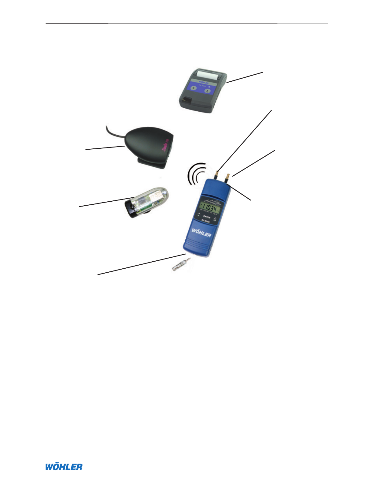
Wohler DC 2000PRO User manual

Pressure Computer Wöhler DC 2000PRO
The Measure of Technology
2015-03-03 Art.-Nr.: 20295
Contents
1. Specifications...........................................2
2. Controls and connections........................5
3. Signal menu .............................................8
4. Stress test (DVGW-TRGI).......................12
5. Main test menu (DVGW-TRGI) ...............14
6. Leakage rates & utility life
measurements........................................20
7. Min, Max, AVG menu .............................21
8. Setup menu for basic settings and logo 22
9. Logger / data transfer ............................27
10. Changing the batteries...........................29
11. Accessories.............................................30
12. Information on disposal...........................30
13. Declaration of conformity.......................31
14. Warranty and service..............................33
Quick reference ........... loose leaf at the centre

2 Hotline +49 29 53/73 100 Fax: 029 53/73 96 100
DC 2000PRO
1. Specifications
1.1 Important information
Before using this instrument, carefully read and observe all notes contained in
these operating instructions.
Fundamentally, skilled personnel only should use the Wöhler DC 2000PRO for
the purpose that it is intended and within the specified data range. No liability
is accepted under any circumstances or guarantee given for results deter-
mined in conjunction with this instrument nor for any damage that may arise
when using this instrument.
The pressure meter can be used on both gaseous media (air or inert gas)
and liquids, e.g. water or fuel oil. In this case, it is important to observe that
remains of liquid at the pressure connections can falsify the result of the fol-
lowing gas measurement. Therefore, the device should no longer be used on
gaseous media, after it has been used to measure liquids.
1. Specifications

e-mail:info@woehler.com www.woehler.com 3
DC 2000PRO
1. 2 Application
The Pressure Computer DC 2000PRO is a high-precision multifunctional meter
for registering differential pressures, flow rates, temperatures, and humidities
(optional). From the basic version on, this device exhibits an extremely wide
dynamic range that not only takes highly sensitive measurements of mini-
mum draughts and gas pressures in the pascal range, but also lets the user
measure leakage rates and examine sealing properties for main assessments
as per DVGW-TRGI and conduct measurements for load tests during pre-
assessments. A maximum measuring range of 2 bar and a rupture pressure
of 3 bar also provide for adequate safety at higher pressure ranges. During all
measurements the user is guided by plaintext instructions on the display.
This device, which can store all measured values in a logger, can also be
used for measurements of (ambient) climates. This is made possible by a
temperature sensor also integrated as standard in addition to the pressure
sensor. Optionally, the range of applications can be expanded with an exter-
nal temperature sensor. Depending on the selected scan rate, all measured
values can be logged for several years and transferred to a PC via the inte-
grated IrDA interface. Measurement records can be sent to a thermal printer
for printouts with the company logo. If needed, continuous IrDA transfer can
be activated in the Setup menu so that during measurements all four mea-
sured values (pressure, external and internal temperature, and humidity) and
their respective channel numbers are transferred to a PC every second.
The extremely low current consumption is made possible by an all-new pro-
cessor technology that automatically and dynamically adapts the power draw
to the measuring task. Also the mode with the maximum current consumption
(6 mA) runs continuously for over 300 hours on two standard AA batteries (2
Ah). In logger mode the device can run on the same batteries and without
memory overflow for several years when the scan rate between two measure-
ments is 4 h (4680 measurements x 4 h). The pressure meter can be used on
both gaseous media (air or inert gas) and liquids, e.g. water or fuel oil. In this
case, it is important to observe that remains of liquid at the pressure connec-
tions can falsify the result of the following gas measurement. Therefore, the
device should no longer be used on gaseous media, after it has been used to
measure liquids.
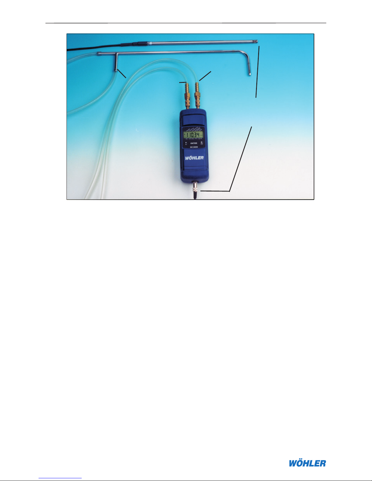
The processor’s arithmetic and logic unit (ALU) can perform simple operations
on the measured values so that, for example, the leakage rate is automatically
displayed in l/h or the flow rate measured with a Prandtl’s tube in m/s.
The German association for safety inspections on gas leak meters, TÜV SÜD
Industrie Service zur Gasleckmengenmessung has certified and approved the
DC 2000PRO in accordance with the new DVGW requirements under VP 952
for low-pressure gas lines complying with DVGW worksheets G 600 and G
624. (DVGW-Certificate DG-4805BQ0012)
1. Specifications

4 Hotline +49 29 53/73 100 Fax: 029 53/73 96 100
DC 2000PRO
1.3 Measured values
Differential pressure measurements (temperature-compensated piezo
bridge)
Measuring range: ±2 bar
1 Pa resolution in measuring range -125.00 hPa to +125.00 hPa, otherwise 10
Pa
Precision: < 3% of measured value, better than ±6 Pa within a range of ±200
Pa.
Internal temperature measurements (NTC)
Measuring range: -20 °C to 60 °C
Precision: < ±2 °C
Resolution: 0.1 °C
External temperature measurements (optional, air temperature sensor
order no. 9605 or air temperature probe order no. 9611)
Measuring range: -19.9 °C to +99.9 °C
Precision: < ±2 °C
Resolution: 0.1 °C
T98: < 120 s at 1.5 m/s
Humidity measurements (optional, order no.: 7203)
Measuring range: 0% to 100% RH (relative humidity), non-condensing
Precision: < ±2% RH, within a range of 0–90% RH, otherwise < 3% RH
Resolution: 1% RH
1.4 Calculated values
Pressure units – conversion to mbar, hPa, Pa, mm·H20, PSI in accordance
with generally applicable conversion rules
Temperature units – conversion from °C to °F in accordance with generally
applicable conversion rules
Flow rates – Prandtl measurements displayed in m/s, automatic continuous
density correction based on temperature signal
Range: 2–150 m/s
Pipeline volumes automatically from 0.0 to 1000.0 l (tested to 250.0 l)
Leakage rate (0.0 to 300.0 l/h) – l/h in accordance with DVGW-TRG work-
sheet G 624. The physical data needed to convert diverse gas types can be
extracted from a database stored in the device.
Pressure drop – pre-assessments and main assessments in accordance
with DVGW-TRGI worksheet G 600
1. Specifications

e-mail:info@woehler.com www.woehler.com 5
DC 2000PRO
Statistical characteristics – minimum, average, maximum of all measured
and calculated values in the respective measurement units
Date and time – output to measurement records.
1.3 Logger mode
Scope – 4680 measurements each with measured pressure and humidity
values and two measured temperature values (when external sensor atta-
ched), i.e. max 18,720 measured values
These measured values can be stored in memory for over ten years, even
without batteries.
IrDA data transfer, also while data are being registered
User-selectable scan intervals – 30 s, 1 min, 3 min, 10 min, 30 min, 1 h, 3 h,
4 h
Control on undervoltage
1.4 Technical data
Current consumption from two AA or dry batteries:
– operating mode: approx. 6 mA
– OFF and logger modes: approx. 16 µA for clock and processor
Interfaces
– infrared data transfer to PC
– in situ printout on thermal printer order no. 9130
Storage temperature – -20 °C to +60 °C
Operating temperature – -5 °C to +60 °C in logger mode (excl. display); incl.
display 0–50 °C
Mass – approx. 450 g with protective bag and magnet excl. hose
Dimensions – 54 x 165 x 52 mm
2. Controls and connections
Figure 1 below shows the indicators and controls on the DC 2000PRO. The
display always shows the trend ▼▲on the left, the numerical value in the
middle, and the corresponding unit of measurement on the right. When a key
is pressed, a cursor ▲ appears in addition at the edge of the display to mark
the subprogram near the display label. This menu is activated when the
cursor flashes.
The functions assigned to the keys resemble those on a mobile phone. In
general, the ± key on the left increments or decrements an entered value or
displaces to the left or right the cursor ▲(1) at the edge of the display (see
Figure). A short double tap on the ± key switches from increment to decre-
ment mode or reverses the cursor’s movements. This toggle function is indi-
cated by a dot at the centre of the display (2). A second double tap switches
back to increment mode or restores the cursor’s original direction.
Example: Pressing the ± key moves the cursor from its position 1 (“Pre-
v
2. Controls and connections

6 Hotline +49 29 53/73 100 Fax: 029 53/73 96 100
DC 2000PRO
assessment”) to “Main assessment” on the right. The cursor is returned to
“Pre-assessment” when the key is first double- then single-tapped (see 2, the
dot “•” indicates active reverse mode).
Figure 2.1 - Display and controls on the DC 2000PRO
The ENTER key at the centre of the control panel confirms the entered value
or activates the program selected at the cursor position.
2. Controls and Connections
1
2
Unit of measurement

e-mail:info@woehler.com www.woehler.com 7
DC 2000PRO
The right C I/O key has two functions. Pressing it once cancels the current
menu option or an incorrectly entered value. Keeping it pressed switches OFF
the device after about three seconds.
Figure 2.2 – Connections and sockets on the DC 2000PRO Pressure Computer
The socket can take a hose with an internal diameter of 5–6 mm or, if the
design of the DC 2000PRO allows this, a DN 2.7-type rapid-action coupling.
Silicone hoses can perforate at overpressures greater than 1 bar, adding to
the leakage rate, so should not be used for these pressure ranges.
In Figure 2.2, the rear of the DC 2000PRO exhibits diffusion apertures for the
internal registration of ambient humidity (optional) and temperature. The
integrated temperature measurement also serves to compensate for tempera-
tures in the pressure sensor. When the device is used as a precision tempera-
ture sensor with extended measuring range (–19.9 °C to +99.9 °C) the exter-
nal combustion air temperature sensor A 500 (order no. 9605) or the external
combustion air probe A 500 (order no. 9611) with a 2 m cable can be used.
The measured data are read out of the logger and transferred to a PC via the
IR (infrared) interface (order no. 9631 serial or 9318 USB or Bluelink 500.)
2. Controls and Connections
IrDA interface
external temperature socket
- underpressure
+ overpressure
humidity sensor (rear)
printer
Bluelink

8 Hotline +49 29 53/73 100 Fax: 029 53/73 96 100
DC 2000PRO
3. Signal menu
Before the device is used, a visual check must ensure each and every time
that all functions work properly. When the device is then switched ON it con-
ducts a self-test. Afterwards the time and date are output. When the device’s
logger mode has been activated, the text “Log” followed by the current
measured and stored values appears instead of the self-test – the device then
switches back OFF. For as long as a flashing cursor points to the subpro-
gram P=0, no hose should be attached and no differential pressure applied:
during this phase the device is stabilising and determining its zero point.
The subsections under this heading describe the basic functions in the Signal
menu item. Pressing the ± key three times moves the cursor to the sub-
program Signal which is activated at the ENTER key (cursor flashes under
Measuring Mode; see Figure 3.1).
Figure 3.1 – Selecting the Signal menu
3.1 Pressure measurements
The subprogram Signal is activated at the ENTER key. The cursor then
flashes and the text “PRESSURE” appears on the display together with the
unit of measurement “mbar”. Now all of the available units can be selected in
turn with the ± key and activated at the ENTER key. In this manner the user
can select one of the following five units for the pressure measurement: Pa,
hPa, mbar, mm·H20, PSI.
3.1.1 Fast pressure measurements (regulator test)
The unit of measurement hPa features in addition under the name “Fast
pressure” a pressure measurement with instantaneous display. This mode
is particularly suitable for gas regulator tests. The measuring process can be
stopped at the ENTER key, and the device displays the last pressure value
measured. This state is complemented by the trend symbols v. The ± key
initiates a single new measurement. Pressing the ENTER key again returns
3. Signal menu
v

e-mail:info@woehler.com www.woehler.com 9
DC 2000PRO
3. Signal Menu
to fast measuring mode. This can be ended with the C I/O key. The device
returns to the normal (battery-saving) measuring mode with the unit chosen
last.
Signal AUTO alternately displays pressure, temperature, and air humidity
values in the pressure and temperature units chosen last.
An overpressure at the socket marked with the + sign and an underpressure
at the socket marked with the – sign causes a positive differential pressure to
be displayed. When the differential pressure exceeds 125 hPa, the device au-
tomatically switches to the higher measuring range up to 2000.0 hPa. When
the value falls below 125 hPa in this measuring range, the display switches
back to a resolution of 1 Pa.
3.2 Flow rate measurements based on Prandtl
The flow rate of air in m/s can be measured with a Prandtl’s tube. This mea-
surement is activated when the ± key is repeatedly pressed in the Measuring
Mode menu until the text “Prandtl” appears with the unit of measurement
“m/s”. The total pressure of the tube is connected to the + overpressure so-
cket and the static pressure to the – underpressure socket on the DC 2000PRO
(see Figure 3.2).
First of all the device must be “zeroed” in a medium at rest (
P=0
). Then the
probe is inserted into the gas or air flow, as parallel as possible and with the
tip facing the flow, and the measured values are read off. The current flow
rate v is automatically calculated with Equation (1). According to Equation (2)
the air density ρ in Equation (1) depends in turn on the absolute air pressure
pcur
and the current temperature
T
.
whereby:
v
flow rate in m/s
Dpdifferential pressure in Pa, measured with the Prandtl’s tube
ρair density in kg/m3
pcur
absolute air pressure in hPa, manual entry in the Setup menu item
(default 1013 hPa)
T
air temperature in °C
The absolute air pressure
pcur
can be set under the menu item Setup > Ab-
solute pressure. This setting is also used to determine leakage rates under
Section 6.
(T(°C) + 273 K) • 1013 hPa
ρ = 1,2 • kg/m3 •
293 K • pakt (hPa) (2)
2 x ∆p
√ρ
v = (1)

10 Hotline +49 29 53/73 100 Fax: 029 53/73 96 100
DC 2000PRO
.
Figure 3.2 – Prandtl’s tube order no. 9487 with combustion air temperature
probe A 500 order no. 9611 for automatic density correction
When the temperature T of the measured air flow deviates from the ambient
temperature of the DC 2000, the combustion air temperature probe can be
inserted over its 2 m cable into the flow parallel to the Prandtl’s tube. There is
then an automatic follow-up of the air density ρas a function of the measured
temperature T according to Equation (2).
3.3 Temperature measurements
Temperature measurements are activated when the ± key in the Signal menu
is repeatedly pressed until the text “Temperature” appears with the unit of
measurement “°C”. Again pressing the ± key switches to the unit of mea-
surement “°F”. The ENTER key confirms the selected measuring mode and
returns to the display.
An external temperature sensor can be connected at any time. In this case
the device switches automatically to the external sensor.
For precision measurements, the sensor’s five-digit calibration number (e.g.
cal. no. 10208) should be entered under TLOff in the Setup menu. This
calibration number is printed on a metal foil provided with every temperature
sensor. When no external sensor is connected, the temperature of an internal
sensor is displayed that also serves to compensate for the temperature of the
pressure and the optional humidity sensor signals. When therefore ambient
static pressure
total pressure
temperature sen-
sor (optional)
3. Signal Menu

e-mail:info@woehler.com www.woehler.com 11
DC 2000PRO
3. Signal Menu
temperatures and humidities are constantly measured the housing should not
be exposed to direct sunlight or heat radiation.
3.4 Humidity measurements
Humidity measurements are activated when the ± key in the Singal menu
is repeatedly pressed until the text “Humidity” appears with the unit of
measurement “%”. The ENTER key confirms the selected measuring mode
and returns to the display. The diffusion aperture on the rear of the housing
should not be obstructed. The humidity sensor is a laser-trimmed, capacitive
sensor element with chip-integrated signal processing. It can be retrofitted or
replaced by the user as well (order no. 7203) after the two calibration values
Zero offset (here 0.833 V, Figure 6) and Slope (here 31.31 mV) have been
entered under the Setup menu.
Figure 3.3 – Position of the humidity sensor when the battery compartment
cover is removed.
The slope value taken from the provided calibration record must be rounded
off to two decimal places (here 31.311 mV —> 31.31 mV).
humidity sensor

12 Hotline +49 29 53/73 100 Fax: 029 53/73 96 100
DC 2000PRO
Figure 3.4 – Calibration record for a humidity sensor
3.5 Automatically alternating display
The program item Measuring Mode AUTO causes the display to alternate
between pressure, temperature, and air humidity values in the pressure and
temperature units chosen last.
4. Stress test (DVGW-TRGI)
Lines with operating pressures up to 100 hPa can be pre-assessed in accor-
dance with DVGW-TRGI worksheet G 600 and the findings documented very
easily with the DC 2000PRO.
First of all, the line must be sealed and a suitable test plug inserted. The
DC 2000PRO must be switched ON before it is connected to the test plug. After
zeroing, press the ± key to activate the menu item stress test.
The DC 2000PRO prompts you to pump to the test pressure (e.g. 1 bar or 1,000
hPa). When the over- and underpressure lines have been swapped over by
accident, the text “Swap” appears on the display. When the pressure reaches
the preset test pressure the stabilising phase is initiated (default Stab. time =
ten minutes). This is marked with the trend symbols ▼▲ . When the pressure
remains within ±10% of the test pressure during this stabilisation phase the
actual pressure loss test is started at the end of the stabilisation time (default
Time = ten minutes). During the stabilisation phase the pressure loss test
can also be initiated manually at the ENTER key. The remaining test time and
the current pressure values are displayed alternately. When the test time has
4. Stress test
Fig. 4.1

e-mail:info@woehler.com www.woehler.com 13
DC 2000PRO
ended or been cancelled with the C I/O key the cursor flashes at Pre-assess-
ment on the display and the results can be viewed in turn at each press of the
± key as follows:
Difference: 54.4 hPa
± key
Start pressure: 1000.3 hPa
± key
Time: 10.00
± key
Stop pressure: 945.9 hPa
± key
Text: “Print …” (activate the printout with the ENTER key)
± key
Difference: 54.4 hPa
etc.
These results can also be printed out or transferred to a PC at a later time
under the menu item Print or Log/IR respectively. By default, the print-out
includes a grafic of the pressure progression. You can disable this function
under the item „grafic“.
The record is not deleted until the logger is started or another TRGI test is
conducted.
3. Stress test

14 Hotline +49 29 53/73 100 Fax: 029 53/73 96 100
DC 2000PRO
5. Main test menu (DVGW-TRGI)
Lines with operating pressures up to 100 hPa can also be main-assessed in
accordance with DVGW-TRGI worksheet G 600 and the findings also docu-
mented very easily with the DC 2000PRO.
First of all, the line must be sealed and a suitable test plug inserted. The
DC 2000PRO must be switched ON before it is connected to the test plug.
After zeroing, press the ± key to activate the menu item Main assessment.
The DC 2000PRO prompts you to pump to the test pressure (e.g. 150 hPa).
When the over- and underpressure lines have been swapped over by acci-
dent, the text “Swap” appears on the display. When the pressure reaches
the preset test pressure the stabilising phase is initiated (default Stab. time =
ten minutes). This is marked with the trend symbols ▼▲. When the pressure
remains within ±10% of the test pressure during this stabilisation phase the
actual pressure loss test is started at the end of the stabilisation time (
default
Time = ten minutes
). During the stabilisation phase the pressure loss test
can also be initiated manually at the ENTER key. The remaining test time and
the current pressure values are displayed alternately. When the test time has
ended or been cancelled with the C I/O key the cursor flashes at Main test on
the display and the results can be viewed in turn at each press of the ± key as
follows:
Difference: 17.7 hPa
± key
Start pressure: 110.83 hPa
± key
Time: 10.00 (minutes)
± key
Stop pressure: 93.14 hPa
± key
Text: “Print …” (activate the printout with the ENTER key)
± key
Difference: 17.7 hPa
5. Main test menu
Fig. 5.1

e-mail:info@woehler.com www.woehler.com 15
DC 2000PRO
etc.
These results are stored in the DC 2000PRO and can also be printed out
or transferred to a PC at a later time under the menu item Print or Log/IR
respectively. The record is not deleted until the logger is started or another
TRGI test is conducted.
5. Main test menu

16 Hotline +49 29 53/73 100 Fax: 029 53/73 96 100
DC 2000PRO
6. Leakage rates and utility life measurements as per DVGW works-
heet G 624
Leakage rates can be determined in accordance with DVGW worksheet G
624 and the findings documented very easily with the DC 2000PRO.
First of all, the line must be sealed and a suitable test plug inserted (see
Section 11). The DC 2000PRO must be switched ON and zeroed before it is
connected to the test plug. After the automatic zeroing, press the ± key to
activate the menu item Utility life / Leakage rate. The display now shows the
text “Pipe volume”. This pipe volume can now be determined either automati-
cally or from a graph.
6.1 Automatically determining pipeline volumes
When the ENTER key is pressed at the same time as the text “Pipe volu-
me” appears, the pipe volume can be determined automatically with the DC
2000PRO. For a pipe volume up to 100 l a syringe takes a sample volume of
100 ml (Figure 6.2 on the left). Lines with volumes greater than 100 l can be
tested with a manual test pump (163 ml/stroke, see figure 6.2 on the right).
Each test volume must be entered in the DC 2000PRO with the ± key and
confirmed with the ENTER key. After a repeated zeroing the DC 2000PRO then
shows the text “Pump”. Now the actual sample can be taken with the medical
syringe or the manual test pump up to the set volume. The DC 2000PRO then
displays automatically the pipe volume calculated with Equation (3). As soon
as the display no longer changes this value is confirmed with the ENTER key
after which it is used as Vpipe for further determinations of leakage rates in
accordance with G 624.
The measuring principle
When a known sample volume Vsample is taken from a pipeline system (e.g.
with a medical syringe or a manual test pump), the total volume Vpipe can be
determined from the resulting pressure change.
For small pipe volumes a medical syringe proves adequate; for larger pipe vo-
Cursorposition:
Utility life/Leaka-
ge rate
6. Leakage rates and utility life measurements

e-mail:info@woehler.com www.woehler.com 17
DC 2000PRO
6. Leakage rates and utility life measurements
lumes a manual test pump can be used. The choice should be such that the
pressure change is at least 5 hPa. Boyle’s law returns the following equation
for the wanted volume Vpipe:
whereby:
Vpipe wanted pipe volume, max 1000.0 l
Vsample sample volume, default 0.100 l, e.g. with 100 ml medical syringe
Δp max pressure difference in Pa caused by the taking of the sample
pabs absolute air pressure, entered manually under the Setup menu
(default 1013 hPa)
Figure 6.2 – Connections for determining the pipe volume Vpipe, with a 100
ml medical syringe (left) or a manual test pump (right)
6.1.1 Determination of the volume of the nozzle
The pressure difference Δp will be measured. It should amount to at least 200
Pa, to get an exact measuring result. Therefore, the volume of the nozzle
VSample must at least amount to 1/500 of the pipe volume. In this case, the ex-
pected error of the result of the volume measurement is equal to the inaccu-
racy of the DC 2000PRO which is 3% of the measured value. A higher pressure
will provoque longer stabilization periods during the temperature compensati-
on and possible leakages will have more influences.
The following table will give you some guiding values for the determination of
Vpipe = Vsample . ( - 1)Temp = const
pakt
Dp(3)

18 Hotline +49 29 53/73 100 Fax: 029 53/73 96 100
DC 2000PRO
The entire printout for this determination of leakage rate specifies and also
documents permanently all interim results for determining the volume. One
advantage of this method lies in the insensitiveness to any pipe leaks: the
small sample volume leads to pressure differences only of a few hPa in the
line. Compared with a usual test pressure of 150 hPa, these low test pres-
sures can scarcely give rise to a perceptible leak.
6.1.2 Determining pipelines from graphs
When the C I/O key is pressed at the same time that the text “Pipe volume”
appears, the pipe volume can then be determined from the pipe lengths and
pipe diameters in figure 6.3 and entered at the ± key. When this entered value
is confirmed with the ENTER key, it is used as Vpipe for determining other lea-
kage rates in accordance with G 624. A blow-up of this diagram can be found
on the front page of the loose leaf inserted at the centre of these operating
instructions.
Figure 6.3 – Aid for determining pipe capacity
For example, a 1/2“ pipe designed with “medium-duty threads in accordance
6. Determining the leakage rate
Aid for determining pipe volumes
Pipe volume (l)
Pipe section length (m)
Volume of the nozzle max. pipe volume (DC 2000PRO)
20 ml 10 l
50 ml 25 l
100 ml 50 l
163 ml (1 stroke with the test pump) 80 l
489 ml (3 strokes with the test pump) 240 l

e-mail:info@woehler.com www.woehler.com 19
DC 2000PRO
with DIN 2440” of 10 m length has a pipe volume of 2 l.
6.3.3 Determining the leakage rate
Once the pipeline volume has been measured or entered the DC 2000PRO
prompts the user to enter the test pressure, the test time, and the opera-
ting pressure of the gas line. Afterwards the line is to be pumped to the test
pressure (e.g. 100 hPa). To do so, replace now the syringe or the manual test
pump with the compressed air pump for applying the test pressure (see Sec-
tion 11). When the over- and underpressure lines have been swapped over by
accident, the text “Swap” appears on the display. When the pressure reaches
the preset test pressure the stabilising phase is initiated (default Stab. time =
ten minutes). This is marked with the trend symbols ▼▲. When the pressure
remains within ±10% of the test pressure during this stabilisation phase the
actual pressure loss test is started at the end of the stabilisation time (default
Time = ten minutes). During the stabilisation phase, e.g. when the pressure
drops greater than 5 hPa, the pressure loss test can also be initiated manually
at the ENTER key. The remaining test time and the current pressure values
are displayed alternately.
When the test time has ended or been cancelled with the C I/O key, e.g. when
the pressure drop is greater than 15 hPa, the cursor flashes at Utility life /
Leakage rate on the display and the results can be viewed in turn at each
press of the ± key as follows:
Difference: 9.9 hPa
± key
Start pressure: 108.83 hPa
± key
Time: 1 min
± key
Stop pressure: 98.96 hPa
± key
Leakage rate: 8.3 l/h hPa
± key
Text: “Print …” (activate the printout with the ENTER key)
± key
Difference: 9.9 hPa
etc.
6. Determining the leakage rate

20 Hotline +49 29 53/73 100 Fax: 029 53/73 96 100
DC 2000PRO
6. Determining the leakage rate
The leakage rate is calculated automatically with the following equations (4)
and (5) and so complies with the procedure under DVGW-TRGI worksheet G
624:
VBgas leakage rate in operating mode in l/h
VLair leakage rate at test pressure
pOmax max operating pressure of the gas in situ
pstart test pressure at start of measurement
pend test pressure at end of measurement
pabs absolute air pressure, entered manually under Abs. pressure in the
menu Setup (default 1013 hPa)
f (absolute air viscosity)/(absolute gas viscosity), selection stored in
Setup under Gas
Tmeas measuring time converted to hours (default 1 min)
Vpipe cubic capacity of the test section in litres (see Figure 7
VL=
V Rohr
T mess
pakt+ pStart
pakt + p Stopp
•
•- 1 (5)
VB= VL • • f
••(4)
pBmax
pStart
Table of contents
Other Wohler Measuring Instrument manuals

Wohler
Wohler RF 220 Hygrotemp User manual

Wohler
Wohler 3343 User manual

Wohler
Wohler RF 220 User manual

Wohler
Wohler Econometer E 98 User manual

Wohler
Wohler DM 602 User manual

Wohler
Wohler IQ 300 User manual

Wohler
Wohler A 400 User manual

Wohler
Wohler VE User manual

Wohler
Wohler A 450 User manual

Wohler
Wohler FA 320 User manual

Wohler
Wohler BC 600 User manual

Wohler
Wohler TA 420 User manual

Wohler
Wohler FA 410 User manual

Wohler
Wohler TI 410 User manual

Wohler
Wohler 5579 User manual

Wohler
Wohler iVAM2-2 User manual

Wohler
Wohler HBF 420 Installation manual

Wohler
Wohler A 550 User manual

Wohler
Wohler CFM 600 User manual

Wohler
Wohler FA 320 User manual