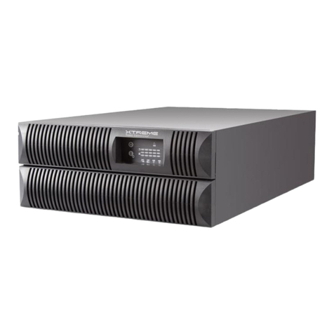
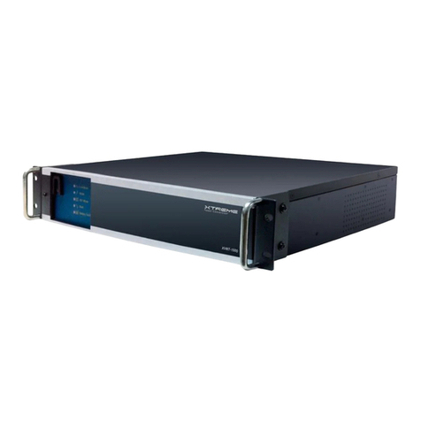
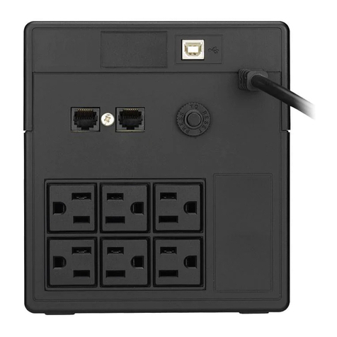
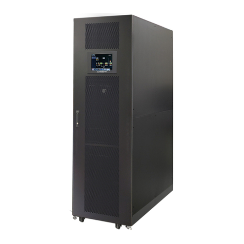
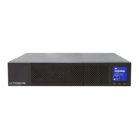
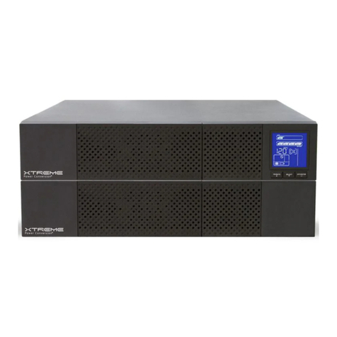
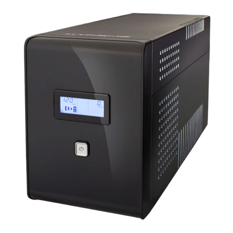
Xtreme G90 User manual

G90 Online UPS
1000VA, 2000VA, 3000VA Models
User & Installaon Manual
www.xpcc.com | © 2015 Xtreme Power Conversion Corporaon. All rights reserved. (Rev 2/5/15)

Xtreme Power Conversion Corporaon
G90 User’s Manual
Page 2
Uninterrupble Power Supply
Table of Contents
Introducon.................................................................................................7
Product Descripon......................................................................................7
Double Conversion Online Technology............................................................................................7
Diagnosc Tests...............................................................................................................................8
System Conguraon...................................................................................8
Communicaon Connecons.........................................................................................................10
Emergency Power O (EPO) Port...................................................................................................11
Hardware Installaon Guide.......................................................................12
Safety Informaon.........................................................................................................................12
Storage and Transportaon...........................................................................................................12
Environment...............................................................................................13
UPS Installaon..........................................................................................13
Connecng the UPS Internal Baeries...........................................................................................13
Connecng Extended Baery Packs (EBPs)...................................................................................15
Rack-mount Installaon.................................................................................................................17
Tower Installaon..........................................................................................................................19
UPS Input Connecon....................................................................................................................21
UPS Output Connecon.................................................................................................................21
Starng the UPS............................................................................................................................ 21
Operaons.................................................................................................23
Front Panel Control Funcons.......................................................................................................23
Indicator Descripons....................................................................................................................23
Buon Descripons.......................................................................................................................24
Working Status of Indicators..........................................................................................................24
Display Funcons...........................................................................................................................25
Parameters Inquiring.....................................................................................................................27
User Sengs..................................................................................................................................29
Operang Mode Descripon.......................................................................33

Xtreme Power Conversion Corporaon
G90 User’s Manual
Page 3
Uninterrupble Power Supply
Startup Operaon..........................................................................................................................34
Shutdown Operaon......................................................................................................................34
UPS Self-Test/Mute Test Operaon................................................................................................35
Conguring Baery Sengs..........................................................................................................35
Using UPS with Generator...........................................................................35
Communicaon..........................................................................................36
Installing Communicaon Opons and Control Terminals............................................................36
Troubleshoong.........................................................................................39
Fault Codes....................................................................................................................................40
UPS Maintenance..........................................................................................................................40
UPS and Baery Care.................................................................................................................... 40
Storing the UPS and Baeries........................................................................................................41
Maintenance..................................................................................................................................41
Replacing Baeries (QUALIFIED SERVICE PERSONNEL ONLY)........................................................41
Replacing Baery Trays in UPS and EBPs.......................................................................................42
Specicaons.............................................................................................45
Shipping List.............................................................................................. 46
Obtaining Service.......................................................................................47
Xtreme Power Conversion Limited Warranty...............................................48
Appendix A: G90-EBP1, G90-EBP2 User Guide.............................................49
Introducon...................................................................................................................................49
Installaon.....................................................................................................................................49
Operaon.......................................................................................................................................51
Maintenance..................................................................................................................................51
Tesng New Baeries....................................................................................................................53
Recycling the Used Baery............................................................................................................53
Specicaons.................................................................................................................................54

Xtreme Power Conversion Corporaon
G90 User’s Manual
Page 4
Uninterrupble Power Supply
Thank you for selecng this uninterrupble power supply (UPS). It provides you with protecon for connected
equipment. Please read this manual before installing the G90 Series UPS models G90-1000, G90-2000, or G90-
3000 as it provides important informaon that should be followed during installaon and maintenance of the UPS
and baeries, allowing you to correctly set up your system for the maximum safety and performance. Included is
informaon on customer support and service, if it is required. If you experience a problem with the UPS, please
refer to the Troubleshoong secon in this manual to correct the problem. If the problem is not corrected, please
collect informaon so that the Technical Support personnel can more eecvely assist you.

Xtreme Power Conversion Corporaon
G90 User’s Manual
Page 5
Uninterrupble Power Supply
Important Safety Instrucons: (Save These Instrucons)
CAUTION! (UPS having Internal Baeries): Risk of electrical shock – Hazardous live parts inside this unit are ener-
gized from the baery supply even when the input AC power is disconnected.
CAUTION! (No User serviceable Parts): Risk of electrical shock, do not remove cover. No user serviceable parts
inside. Refer servicing to qualied service personnel.
CAUTION! (Non-isolated Baery supply): Risk of electric shock, baery circuit is not isolated from AC input, haz-
ardous voltage may exist between baery terminals and ground. Test before touching.
WARNING! (Fuses): To reduce the risk of re, replace only with the same type and size of fuse.
WARNING! Unit intended for installaon in a controlled environment.
CAUTION! Do not dispose of baeries in a re, the baery may explode.
CAUTION! Do not open or mulate the baery, released electrolyte is harmful to the skin and eyes.
CAUTION! A baery can present a risk of electric shock and high short circuit current. The following precauon
should be observed when working on baeries:
• Remove watches, rings or other metal objects.
• Use tools with insulated handles.
To reduce the risk of electric shock, disconnect the UPS from the main supply before installing a computer inter-
face signal cable. Reconnect the power cord only aer signaling interconnecons have been made.
Servicing of baeries should be performed or supervised by personnel with knowledge of baeries and the re-
quired precauons. Keep unauthorized personnel away from baeries.
These UPS units are extremely heavy. Cauon should be taken in moving and posioning equipment.
The instrucons contained within this safety manual are deemed important and should be closely followed at all
mes during installaon and follow-up maintenance of the UPS and baeries.

Xtreme Power Conversion Corporaon
G90 User’s Manual
Page 6
Uninterrupble Power Supply
CAUTION
The unit has a dangerous amount of voltage. If the UPS indicator is on, the unit’s outlets may have a dan-
gerous amount of voltage even when not plugged into the wall outlet because the baery may connue
to supply power.
Care should be taken to undertake installaon indoors, free from electrically-conducve parcles which
are under temperature and humidity control, in order to reduce the risk of electric shock.
It is best to disconnect the device using the power supply cord. Ensure that the equipment is placed in a
posion near the outlet where easily accessible.
Except for replacing the baeries, all servicing on this equipment must be carried out by qualied service
personnel.
Before conducng any maintenance, repair, or shipment, rst ensure that everything is turned o com-
pletely and disconnected.
For addional safety instrucons, please use the Safety Manual as a reference.
Special Symbols
The following symbols used on the UPS warn you of precauons:
RISK OF ELECTRIC SHOCK - Please observe the warning that a risk of electric shock is present
CAUTION: REFER TO OPERATOR’S MANUAL - Refer to the operator’s manual for addional informaon,
such as important operang and maintenance instrucons.
SAFE GROUNDING TERMINAL - Indicates primary safe ground
LOAD ON/OFF – Pressing the buon turns on/o the output receptacles and the indicator light.
RJ45 RECEPTACLE – The receptacle provides network interface connecons and telephone or telecommu-
nicaons equipment should not be plugged into it.
Please do not discard of the UPS or the UPS baeries as the UPS may have valve-regulated lead-acid bat-
teries. Please recycle baeries appropriately.

Xtreme Power Conversion Corporaon
G90 User’s Manual
Page 7
Uninterrupble Power Supply
Introducon
The informaon provided in this manual covers single phase 1000 – 3000 VA uninterrupble power system, their
basic funcons, operang procedures, opons available and emergency situaons. It also includes informaon on
how to ship, store, handle, and install the equipment. Only detailed requirements of the UPS units are described
herein, and installaon must be carried out in accordance with this manual. Electrical installaon must also care-
fully follow local legislaon and regulaons. Only qualied personnel should conduct these installaons as failure
to acknowledge electrical hazards could prove to be fatal.
Product Descripon
Many dierent kinds of sensive electrical equipment can be protected by an Uninterrupble Power Supply (UPS)
including computers, workstaons, process control systems, telecommunicaons systems, sales terminals, other
crical instrumentaon, etc. The purpose of the UPS is to protect these systems from poor quality ulity power,
complete loss of power, or other associated problems.
Electrical interference exists in many forms, causing problems in AC power, from lightning, power company ac-
cidents and radio transmission motors, air condioners, and vending machines. Protecon of sensive electrical
equipment is vital to protect against power outages, low or high voltage condions, slow voltage uctuaons,
frequency variaons, dierenal and common-mode noise, transients, etc.
To prevent power line problems from reaching crical systems causing damage to soware, hardware, and equip-
ment malfuncons, the UPS maintains constant voltage, isolang crical load output and cleaning the ulity AC
power.
Double Conversion Online Technology
A double conversion on-line technology UPS provides completely isolated, clean, uninterrupted single-phase pow-
er to your crical systems, while maintaining the baeries for their maximum potenal. In the event that the
power failure lasts longer than the UPS backup me, the UPS will shut down avoiding baery damage. When the
input AC voltage returns, the UPS will automacally return online to recharge the baeries.
As shown in block diagram:
• An input lter reduces transients on the incoming ulity.
• To maintain full baery charge, the AC input power is reced and regulated in the recer feeding power
to the baery converter and inverter.
• DC power is converted to AC in the inverter, passing it on to the load.
• Power is maintained from the baery during a power failure.
• The converter increases voltage appropriately for the inverter.

Xtreme Power Conversion Corporaon
G90 User’s Manual
Page 8
Uninterrupble Power Supply
Block Diagram
Diagnosc Tests
When the UPS is started, a diagnosc test is automacally executed, checking the electronics and baeries, report-
ing any problems on the LCD display.
System Conguraon
The UPS device and the internal baeries make up the system. Depending on the site and load requirements of the
installaon, certain addional opons are available for the soluon.
Planning a UPS system, the following should be taken into consideraon:
• The total demand of the protected system shall dictate the output power rang (VA). Allow a margin for
future expansion or calculaon inaccuracies from measured power requirements.
• Backup me required will indicate the baery size needed. If the load is less than the UPS nominal power
rang, then actual backup me is longer.
• The following opons are available:
o Connecvity Opons
SNMP/WEB card
Dry contact card
o Extended Baery Packs
G90-EBP1 for use with the G90-1000
G90-EBP2 for use with the G90-2000 and G90-3000
See the Specicaon secon of this manual for addional model informaon.

Xtreme Power Conversion Corporaon
G90 User’s Manual
Page 9
Uninterrupble Power Supply
UPS FRONT VIEW
EBP FRONT VIEW
G90-1000 REAR VIEW DIAGRAM
G90-2000 REAR VIEW DIAGRAM
G90-3000 REAR VIEW DIAGRAM

Xtreme Power Conversion Corporaon
G90 User’s Manual
Page 10
Uninterrupble Power Supply
G90-EBP1 BATTERY PACK REAR VIEW DIAGRAM
G90-EBP2 BATTERY PACK REAR VIEW DIAGRAM
FRONT PANEL
Communicaon Connecons
To allow for unaended UPS shutdown/start-up and status monitoring, connect one end of the communicaon
cable to the USB/RS232 port and the other to the communicaons port on your PC or server. With the monitoring
soware installed, the UPS can be scheduled for shutdown/start-up and monitoring of the UPS status through the
PC or server.

Xtreme Power Conversion Corporaon
G90 User’s Manual
Page 11
Uninterrupble Power Supply
RS232 Communicaons
The RS-232 interface uses a 9-pin female D-sub connector. Informaon provided includes data about ulity, load
and the UPS. The interface port pins and their funcons are idened in the following table:
PIN # FUNCTIONS
1,4,6,7,8,9 Reserved
2 UPS transmit
3 UPS receive
5Ground
SNMP Communicaons Opon
The UPS provides an intelligent slot for internal or external network card. This special intelligent network card can
be compable with popular soware and hardware found on the web and in operang systems. It can support op-
erang systems such as HP Open View, IBM Netview, SUN Netmanager, etc. This enables the UPS to provide instant
UPS and power informaon over the network. Please contact your reseller for addional details.
Emergency Power O (EPO) Port
A customer supplied switch located remotely can be used to close the EPO connecon and allows the UPS output
receptacles to be switched o. Since the EPO shuts down the equipment immediately, orderly shutdown proce-
dures are not followed by any power management soware. The UPS will have to be manually restarted in order
to regain power to the outlets on the UPS.
Keep Pin 1 and Pin 2 closed for UPS normal operaon. To acvate EPO funcon, cut the wire between Pin 1 and
Pin 2.
Warning: The EPO circuit is an IEC 60950 safety extra low voltage (SELV) circuit. This circuit must be
separated from any hazardous voltage circuits by reinforced insulaon.
Cauon: The EPO must not be connected to any ulity connected circuits. Reinforced insulaon to the
ulity is required. The EPO switch must have a minimum rang of 24VDC and 20mA, and be a dedicated latching-
type switch, not ed to another circuit. The EPO signal must remain acve for at least 250ms for proper operaon.
To ensure the UPS stops supplying power to the load during any mode of operaon, the input power must be
disconnected from the UPS when the emergency power o funcon is acvated.
Note: For Europe, the emergency switch requirements are detailed in Harmonized document HD-384-48 S1, “Elec-
trical Installaon of the Buildings, Part 4: Protecon for Safety Chapter 46: Isolaon and Switching”.

Xtreme Power Conversion Corporaon
G90 User’s Manual
Page 12
Uninterrupble Power Supply
Hardware Installaon Guide
Inspect the UPS upon receipt. The packaging is recyclable; keep it for reuse or dispose of properly.
Safety Informaon
Informaon presented here is vital to all personnel. Please read all Safety informaon.
Storage and Transportaon
Please handle the UPS and associated equipment with extreme cauon since a high amount of energy is contained
in the baeries. Always keep the unit in an upright posion as marked on the packaging, and never drop the unit.
Please adhere to the following instrucons if the UPS is not installed immediately:
• Store the equipment as is in its original packing and shipping carton.
• Do not store in temperatures outside the range of -15°C to +25°C
• Ensure that the equipment is fully protected from wet or damp areas and from moist air.
In order to maintain the baeries, the UPS should be recharged every 6 months for at least 8 hours.
If ammable substances such as gases or fumes are present, or if the room is airght, a hazardous situaon may
exist in which no electrical equipment should be operated.
The instrucons in this manual explain how to install the UPS safely. Not acknowledging such electrical hazards
may be fatal – keep this manual for future reference.
WARNING!
It is strongly recommended that the UPS cabinet not be opened as components have very high voltage
and touching those components may be fatal. Only a qualied technician or authorized agent may service
the unit.
The UPS unit’s output receptacles carry live voltage even when not connected to an input voltage source.
The UPS has its own internal energy source.

Xtreme Power Conversion Corporaon
G90 User’s Manual
Page 13
Uninterrupble Power Supply
Environment
Ensure that all environmental concerns and requirements are met according to specicaons listed in this docu-
ment, otherwise the safety of installaon personnel cannot be guaranteed, and the unit may malfuncon.
Ensure that you remember the following when locang the UPS system and baery opons:
• Avoid extremes of temperature and humidity. Maximum baery life can be aained with a recommended
temperature range of +15°C to +25°C.
• Provide protecon for the equipment from moisture.
• Space and venlaon requirements must be met. Ensure there is 100mm behind and 50mm on the sides
of the UPS for proper venlaon.
• Ensure that the front of the UPS remains clear for user operaon.
UPS Installaon
Installaon and wiring must be performed in accordance with the local electrical laws and regulaons, and per-
formed by appropriate personnel.
For safety consideraons, the UPS is shipped from the factory without connecng the baery wires. Before install-
ing the UPS, please follow these steps for connecon of the baery wires.
Connecng the UPS Internal Baeries
Step 1
Remove the front cover of the UPS by holding in the cover side with the LCD display, then un-snap the other side
of the front panel from the UPS. The front panel should now easily be removed from the LCD side.
Note: A ribbon cable connects the LCD to the cover of the UPS. Do not pull on the cable or disconnect it.

Xtreme Power Conversion Corporaon
G90 User’s Manual
Page 14
Uninterrupble Power Supply
Step 2
Cauon: A small amount of arcing may occur when connecng the internal baeries. This is normal and will not
harm personnel. Connect the cables quickly and rmly.
Connect the internal baery connector - connect red to red, pressing the connector ghtly together to ensure
proper connecvity.
If installing an Extended Baery Pack (EBP) see the secon tled Connecng EPBs before connuing with the UPS
installaon
Step 3
Replace the UPS front cover, verifying that the ribbon cable is protected, and if EBPs are installed, that the EBP
cable is routed through the knockout on the boom of the cover.

Xtreme Power Conversion Corporaon
G90 User’s Manual
Page 15
Uninterrupble Power Supply
Aach the UPS front cover by reversing the process in Step 1 – installing the LCD side rst and then gently snapping
the other side into the ports on the UPS.
Step 4
If you are installing power management soware, connect your computer to one of the communicaon ports or
oponal connecvity card, using appropriate cable.
Step 5
If your rack has conductors for grounding or bonding of ungrounded metal parts, connect the ground cable (not
supplied) to the ground bonding screw on the rear of the UPS as shown in the example below.
Step 6
If an emergency power o (disconnect) switch is required by local codes, see “Remote Emergency Power o
(REPO)” secon to install the REPO switch before powering on the UPS.
Connue to “UPS Internal Startup”.
Connecng Extended Baery Packs (EBPs)
Step 1
Remove the front cover of the UPS and each EBP by holding in the cover side with the LCD display, then un-snap
the other side of the front panel from the UPS. The front panel should now easily be removed from the LCD side.
Note: a ribbon cable connects the LCD to the cover of the UPS. Do not pull on the cable or disconnect it.

Xtreme Power Conversion Corporaon
G90 User’s Manual
Page 16
Uninterrupble Power Supply
Step 2
On the boom of the UPS front cover, remove the EBP Cable Knockout as shown in the diagram below.
For the boom EBP, remove the EBP Cable Knockout on the top of the EBP front cover. If you are installing more
than one EBP, for each addional EBP, remove the EBP Cable Knockout on the top and boom of the EBP front
cove r.
Step 3
Cauon: A small amount of arcing may occur when connecng the internal baeries. This is normal and will not
harm personnel. Connect the cables quickly and rmly.
Connect the EBP cables into the baery connector(s) - connecng black to black – press the connectors ghtly
together to ensure proper connecon.
To connect the second EBP, unclip the EBP connector on the rst EBP and pull gently to extend the wiring to the
EBP connector on the second EBP. Repeat for any addional EBPs.

Xtreme Power Conversion Corporaon
G90 User’s Manual
Page 17
Uninterrupble Power Supply
Verify that the EBP connecons are ght and there are adequate bend radiuses and strain relief exists for each
cable.
Step 4
Replace the front covers on the UPS and EBPs, verifying the EBP cables are routed through the EBP cover knock-
outs. Clip the le side of each EBP in place rst before connecng the right side. Repeat for each EBP. This is the
same installaon procedure as used for the UPS earlier.
Assure that the wires connected between the UPS and EBP are installed behind the front covers and not accessible
to the user.
Rack-mount Installaon
Cauon: The UPS and EBPs are heavy. Removing the units from its carton requires a minimum of two people. If in-
stalling oponal EBPs, make sure to install the EBPs directly below the UPS so that all wiring between the cabinets
is installed behind the front covers and inaccessible to users.
Note: Rail Kits are required for each individual UPS and EBP to be installed.
Step 1
Assemble the le and right rails to the rear rails as sown in the diagram below. Do not ghten the screws yet. Ad-
just each rail size for the depth of the rack.
Step 2
Select the proper size in the rack for posioning the UPS. The rail occupies four posions on the front and rear of
the rack.

Xtreme Power Conversion Corporaon
G90 User’s Manual
Page 18
Uninterrupble Power Supply
Tighten four M5 Umbrella Nuts in the side of rail assembly
Fix one rail assembly to the front of the rack with one M5 x 12 pan-head screw and one M5 cage nut. Use two M5
cage nuts and two M5 x 12 pan-head screws to x the rail assembly to the rear of the rack.
Tighten all screws and nuts.
Repeat steps for the other rail assemblies.
Step 3
Place the UPS or EBP on a at, stable surface with the front of the UPS or EBP facing you.
Align the mounng brackets with the screw holes on each side of the UPS or EBP and x with supplied M4 x 8 at-
head screws.
Slide the UPS or EBP into the rack.
Secure the front of the UPS to the rack using one M5 x 12 pan-head screw and one M5 cage nut on each side.
Install the boom screw on each side through the boom hoes of the mounng bracket and the boom hole of
the rail.

Xtreme Power Conversion Corporaon
G90 User’s Manual
Page 19
Uninterrupble Power Supply
Repeat for all addional UPS or EBP for the installaon.
Tower Installaon
Step 1
Two plasc base brackets intercross and aen to make a single unit tower bracket.
If an EBP is to be placed in the tower conguraon with the UPS, extension boards are added in the middle to make
the tower bracket larger as shown below.

Xtreme Power Conversion Corporaon
G90 User’s Manual
Page 20
Uninterrupble Power Supply
Step 2
Install the UPS and associated EBPs into the tower brackets as shown below.
Table of contents
Other Xtreme UPS manuals
Popular UPS manuals by other brands
Tripp Lite
Tripp Lite SMART1200LCD quick guide
Tripp Lite
Tripp Lite ECO-UPS ECO850LCD specification
Tripp Lite
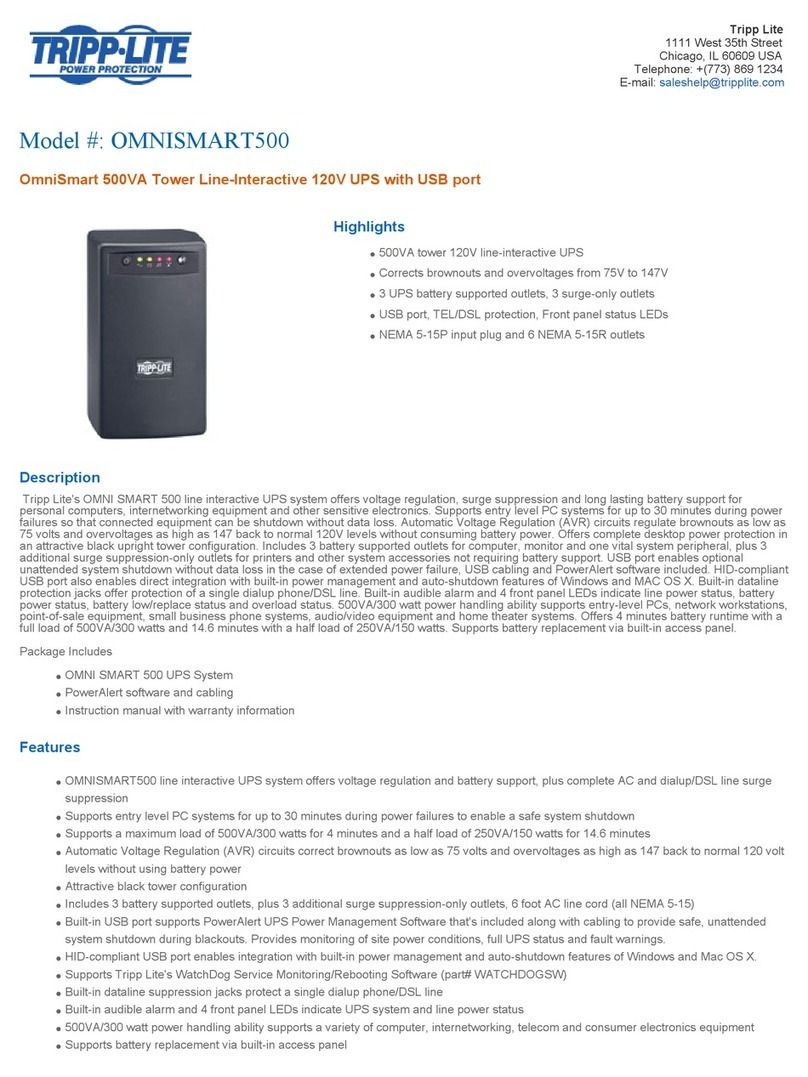
Tripp Lite OmniSmart OMNISMART500 manual

Tripp Lite
Tripp Lite AGSM5060 owner's manual
Tripp Lite
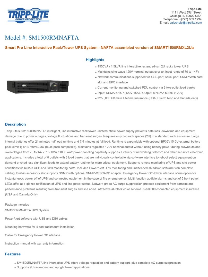
Tripp Lite SM1500RMNAFTA Specification sheet
Tripp Lite
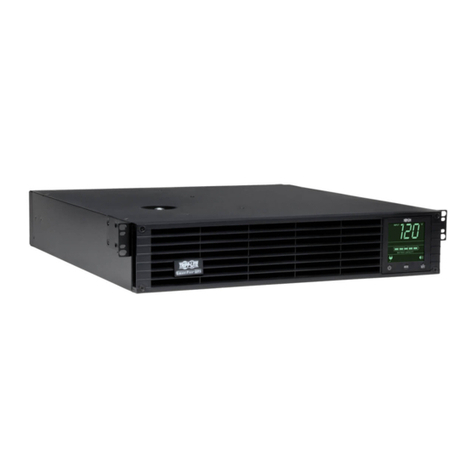
Tripp Lite SmartPro AGSM8207 Series owner's manual

Tripp Lite
Tripp Lite SmartOnline owner's manual

Tripp Lite
Tripp Lite Audio/Video Pure Sine Wave UPS System owner's manual
PowerWalker
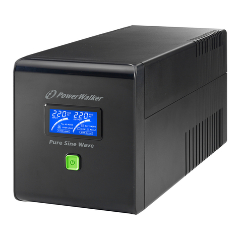
PowerWalker VI 750 PSW quick start guide
Tripp Lite
Tripp Lite SMART550USBWD Specification sheet

Tripp Lite
Tripp Lite SmartPro SMARTINT2200VS owner's manual
Tripp Lite
Tripp Lite SmartOnline SU3000XLCD Specifications


