Xtreme 6kVA Guide

XPRT 6kVA & 10kVA Online UPS
6kVA, 10kVA Models
User & Installaon Manual
www.xpcc.com | © 2015 Xtreme Power Conversion Corporaon. All rights reserved. (Rev 1/26/15)

Xtreme Power Conversion Corporaon
XPRT 6kVA & 10kVA User’s Manual
Page 2
Uninterrupble Power Supply
Table of Contents
EMC Statements - FCC Part 15......................................................................5
Safety Warnings And Symbols......................................................................5
Safety Warnings...............................................................................................................................5
SafetySymbols.................................................................................................................................6
General........................................................................................................6
Transport/Storage........................................................................................7
Maintenance And Servicing..........................................................................7
Introducon.................................................................................................8
Product Descripon......................................................................................8
Double Conversion On-Line Technology..........................................................................................8
Eciency Opmizer Funcon..........................................................................................................9
Free Run Mode................................................................................................................................9
Diagnosc Tests...............................................................................................................................9
System Conguraon.....................................................................................................................10
Hardware Installaon Guide.......................................................................15
Safety Informaon.........................................................................................................................15
Installaon Procedures..................................................................................................................16
Connecng Internal Baery Pack (6kVA Model)............................................................................19
Connecng Internal Baery Pack (10kVA Model)..........................................................................21
Connecng Addional External Baery Packs (6kVA Model)........................................................22
Connecng Addional External Baery Packs (10kVA Model)......................................................24
Connecng Interface Devices........................................................................................................27
Standard Hardwired Installaon Procedure..................................................................................29
Oponal Power Distribuon Units.................................................................................................32
Startup.......................................................................................................34
Startup 6kVA UPS..........................................................................................................................34
Startup 10kVA UPS (stand-alone not parallel systems)..................................................................35
Operaon...................................................................................................36

Xtreme Power Conversion Corporaon
XPRT 6kVA & 10kVA User’s Manual
Page 3
Uninterrupble Power Supply
Normal Operaon Condions........................................................................................................36
Switching the UPS OFF...................................................................................................................37
Maintenance Bypass......................................................................................................................38
10kVA Parallel Installaon And Operaon..................................................40
Installaon of a Parallel System.....................................................................................................40
Installing the Parallel Connecon..................................................................................................41
Startup 10kVA UPS Parallel System................................................................................................43
Normal Operaon Condions........................................................................................................43
Switching the UPS OFF...................................................................................................................43
Status and Alarm Indicaons......................................................................45
On Bypass......................................................................................................................................45
On Baery......................................................................................................................................46
Baery Low (end of runme)........................................................................................................46
Bypass Out of Limits......................................................................................................................46
Overload........................................................................................................................................46
Replace Baery..............................................................................................................................47
Alarm Priority.................................................................................................................................47
Fault Mode....................................................................................................................................48
Standby..........................................................................................................................................48
Remote Emergency Power O (REPO)...........................................................................................48
No Load Shutdown........................................................................................................................49
Auto Restart...................................................................................................................................49
Baery Management.................................................................................50
Baery Connecon Test................................................................................................................50
Quick Baery Test......................................................................................................................... 50
Deep Baery Test..........................................................................................................................50
Communicaon..........................................................................................50
RS-232 Communicaon Port.........................................................................................................50
SNMP Interface Card (Opon).......................................................................................................51

Xtreme Power Conversion Corporaon
XPRT 6kVA & 10kVA User’s Manual
Page 4
Uninterrupble Power Supply
Extended Runme......................................................................................51
Maintenance..............................................................................................52
Safety.............................................................................................................................................52
General..........................................................................................................................................52
Recycling the UPS at the End of Service Life..................................................................................52
Baeries.........................................................................................................................................53
Internal Baery Replacement – 6kVA Model.................................................................................53
Internal Baery Replacement – 10kVA Model..............................................................................54
Power Unit Maintenance...............................................................................................................56
Power Unit Replacement – 6kVA Model........................................................................................56
Power Unit Replacement – 10kVA Model......................................................................................56
Troubleshoong.........................................................................................58
Specicaons.............................................................................................59
Shipping List.............................................................................................. 59
Obtaining Service.......................................................................................60
Xtreme Power Conversion Limited Warranty..............................................61
Xtreme Power Conversion Load Protecon Policy.......................................62
Appendix A: SNMP/WEB Card (Oponal)....................................................65
Introducon...................................................................................................................................65
LEDs.............................................................................................................................................. 65
Features.........................................................................................................................................65
Architecture...................................................................................................................................66
Interfaces.......................................................................................................................................67
Conguraon.................................................................................................................................67
Access............................................................................................................................................69

Xtreme Power Conversion Corporaon
XPRT 6kVA & 10kVA User’s Manual
Page 5
Uninterrupble Power Supply
Thank you for selecng this uninterrupble power supply (UPS). It provides you with protecon for connected
equipment. Please read this manual before installing the XPRT-Series UPS models XPRT-6000 and XPRT-10000 as it
provides important informaon that should be followed during installaon and maintenance of the UPS and bat-
teries, allowing you to correctly set up your system for the maximum safety and performance. Included is informa-
on on customer support and service, if it is required. If you experience a problem with the UPS, please refer to
the Troubleshoong secon in this manual to correct the problem. If the problem is not corrected, please collect
informaon so that the Technical Support personnel can more eecvely assist you.
EMC Statements - FCC Part 15
Noce: This equipment has been tested and found to comply with the limits for a Class A digital device, pursuant
to Part 15 of the FCC Rules. These limits are designed to provide reasonable protecon against harmful interfer-
ence when the equipment is operated in a commercial environment. This equipment generates, uses, and can
radiate radio frequency energy and, if not installed and used in accordance with the instrucon manual, may cause
harmful interference to radio communicaons. Operaon of this equipment in a residenal area is likely to cause
harmful interference in which case the user will be required to correct the interference at the users own expense.
Modicaons not expressly approved by the manufacturer could void the user’s authority to operate the equip-
ment under FCC rules.
IMPORTANT SAFETY INSTRUCTIONS: (SAVE THESE INSTRUCTIONS)
This manual contains important instrucons that should be followed during installaon and maintenance of the
UPS. It also gives all necessary informaon about the correct use of the UPS. Before aempng to install and start
up the UPS, carefully read this manual. Keep this manual next to the unit for future references.
Full understanding of and compliance with the safety instrucons and warnings contained in this manual are the
ONLY CONDITIONS to avoid any dangerous situaon during installaon, operaon and maintenance work, and to
preserve the maximum reliability of the UPS system.
Xtreme Power Conversion (XPC) Corp refuses any responsibility in case of non-observance, unauthorized altera-
ons, or improper use of the delivered UPS.
While every care has been taken to ensure the completeness and accuracy of this manual, XPC accepts no respon-
sibility or liability for any loss or damage resulng from the use of the informaon contained in this document.
This document shall not be copied nor reproduced without the permission of XPC.
Due to technical improvements, some of the informaon contained in this manual may be changed without noce.
The instrucons in this manual are for UPS models XPRT-6000 and XPRT-10000. Check your model number by
looking at the top cover of your UPS. Any dierence in instrucons is clearly indicated in the text (for instance
‘XPRT-10000).
Safety Warnings And Symbols
Safety Warnings
The text of this manual contains warnings to avoid risk to persons and to avoid damages to the UPS system and the
supplied crical loads. Do not proceed beyond these warnings if you do not fully understand and/or are not able
to meet the menoned condions.

Xtreme Power Conversion Corporaon
XPRT 6kVA & 10kVA User’s Manual
Page 6
Uninterrupble Power Supply
The non-observance of the warnings reminding hazardous situaons could result in human injury and equipment
damage.
Please pay aenon to the meaning of the following warnings and symbols.
WARNING!
Refers to procedures or operaons which, when not correctly performed, could cause per-
sonal injury or serious damage to the system.
NOTE
Warns the user about important operaons or procedures described in this manual.
Safety Symbols
CAUTION
The product may be in danger: when procedures or operaons are not correctly performed,
damage to the product may be the result.
DANGER OF ELECTRICALLY LIVE PARTS
Related to all situaons with potenally hazardous voltage.
NOTE
Check for sucient oor and elevator loading capacity. Move the UPS and the baery pack in
its original package to the nal desnaon room. Do not stack other package on top.
WARNING!
Pay aenon to the HEAVY WEIGHT of the UPS when downloading the UPS from the pallet!
Never try to li the unit by yourself!
General
DANGER! RISK OF ELECTRIC SHOCK.
The UPS has an internal baery supply with a nominal voltage of 144VDC (6kVA) 288VDC
(10kVA). Some of the parts of the UPS are necessarily under a hazardous voltage. Do not open
the unit; there are no user serviceable parts inside. The outlets and output terminals may be
electrically live, even when the UPS is disconnected from the ulity power.
CAUTION
There may be damage to the equipment if procedures and pracces are not strictly observed
and followed.

Xtreme Power Conversion Corporaon
XPRT 6kVA & 10kVA User’s Manual
Page 7
Uninterrupble Power Supply
Transport/Storage
NOTE
Check for sucient oor and elevator loading capacity. Move the UPS and the baery pack in
its original package to the nal desnaon room. Do not stack other package on top.
WARNING!
Pay aenon to the HEAVY WEIGHT of the UPS when removing the UPS from the pallet! Never
try to li the unit by yourself!
No liability can be accepted for any transport damage when the equipment is not shipped in original packaging.
Store the UPS in a dry locaon with the baeries in a fully charged state. Storage temperature must be within -20
+45°C (-4°F and 113°F). If the unit is stored for a period exceeding 3 months, opmal baery lifeme is obtained if
the storage temperature does not exceed 30°C (86°F).
If the unit is stored for an extended period of me, the baeries must be recharged periodically. Connect the unit
to a wall outlet and recharge the baeries for 24 hours:
• if the storage temperature is within -20 and +30°C (-4°F and 86°F): every 3 months
• if the storage temperature is within -20 and +45°C (-4°F and 113°F): every 1 month
CAUTION
In case of storage, pay aenon to:
Maintenance And Servicing
• All maintenance and servicing, except replacement of the baeries and plug-in cards, is to be carried out
by qualied skilled personnel only
• A baery can present a risk of electrical shock and high short circuit current
• Never dispose of baeries in a re: they may explode
• Do not open or mulate baeries: their contents may be extremely toxic. If exposed to electrolyte, wash
immediately with plenty of water
• The baeries must be disconnected during maintenance or service work
• When replacing the baeries, use only the same type and size baery
• The following precauons should be observed when working on baeries:
ᴏ Remove watches, rings or other metal objects
ᴏ Use tools with insulated handles
ᴏ Wear rubber gloves and boots
ᴏ Do not lay tools or metal parts on top of baeries
ᴏ Disconnect charging source prior to connecng or disconnect baery terminals
ᴏ Determine if the baery is inadvertently grounded. If inadvertently grounded, remove source of
ground. Contact with any part of a grounded baery can result in electrical shock. The likelihood
of such shock will be reduced if such grounds are removed during installaon and maintenance.
• Avoid charging in a sealed container

Xtreme Power Conversion Corporaon
XPRT 6kVA & 10kVA User’s Manual
Page 8
Uninterrupble Power Supply
NOTE
Do not aempt to service the UPS unless you have had proper training. Refer all maintenance
and servicing, except replacement of the baeries, power unit (10kVA), and plug-in cards, to
properly qualied, skilled, and competent service personnel.
Qualied, skilled personnel are persons who (because of their training, experience, and posion as well as their
knowledge of appropriate standards, regulaons, health and safety requirements and working condions) are
authorized to be responsible for the safety of the equipment, at all mes whilst carrying out their normal dues
and are therefore aware of, and can report, possible hazards (observe IEC 60364 and naonal wiring regulaons
and accident prevenon rules).
Introducon
The informaon provided in this manual covers single phase 6000 and 10000 VA uninterrupble power systems,
their basic funcons, operang procedures, opons available, and emergency situaons. It also includes informa-
on on how to ship, store, handle, and install the equipment. Only detailed requirements of the UPS units are
described herein, and installaon must be carried out in accordance with this manual. Electrical installaon must
also carefully follow local legislaon and regulaons. Only qualied personnel should conduct these installaons
as failure to acknowledge electrical hazards could prove to be fatal.
Product Descripon
Many dierent kinds of sensive electrical equipment can be protected by an Uninterrupble Power Supply (UPS)
including computers, workstaons, process control systems, telecommunicaons systems, sales terminals, other
crical instrumentaon, etc. The purpose of the UPS is to protect these systems from poor quality ulity power,
complete loss of power, or other associated problems.
Electrical interference exists in many forms, causing problems in AC power, from lightning, power company ac-
cidents and radio transmission motors, air condioners, and vending machines. Protecon of sensive electrical
equipment is vital to protect against power outages, low or high voltage condions, slow voltage uctuaons,
frequency variaons, dierenal and common-mode noise, transients, etc.
To prevent power line problems from reaching crical systems causing damage to soware, hardware, and equip-
ment malfuncons, the UPS maintains constant voltage, isolang crical load output and cleaning the ulity AC
power.
Double Conversion On-Line Technology
A double conversion on-line technology UPS provides completely isolated, clean, uninterrupted single-phase pow-
er to your crical systems, while maintaining the baeries for their maximum potenal. In the event that the
power failure lasts longer than the UPS backup me, the UPS will shut down avoiding baery damage. When the
input AC voltage returns, the UPS will automacally return online to recharge the baeries.
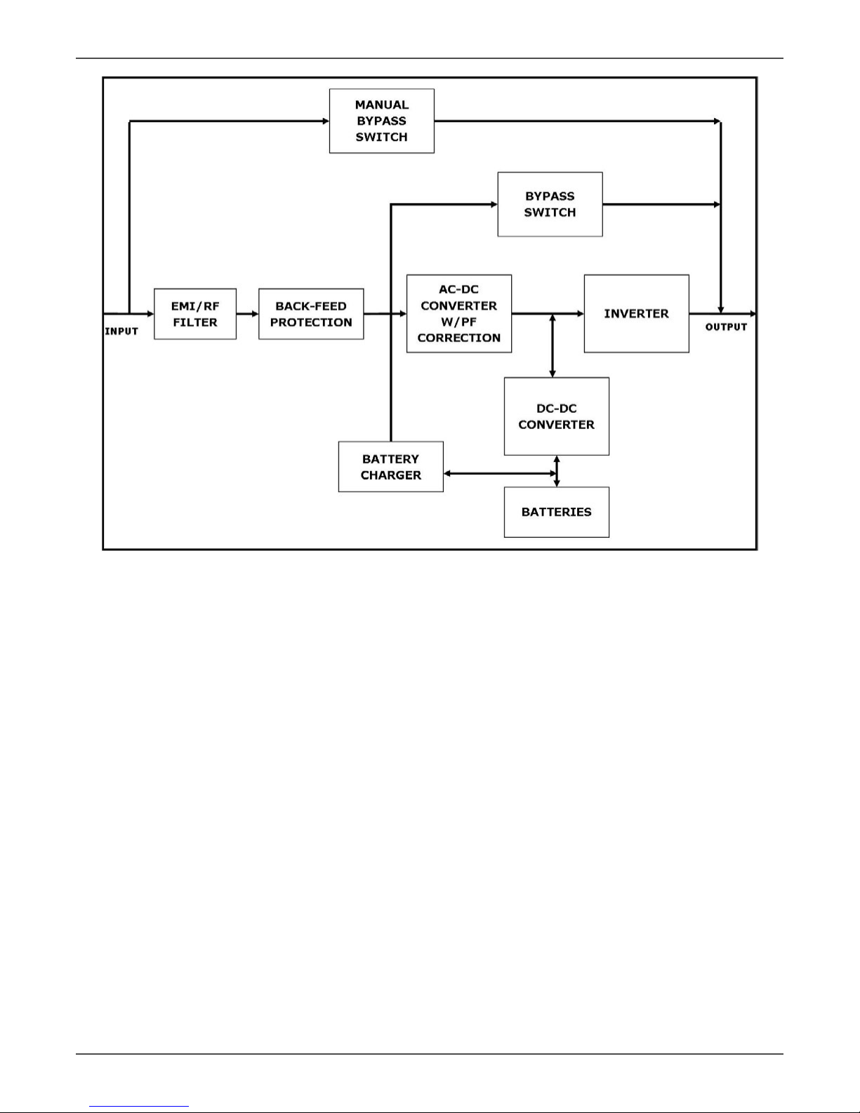
As shown in the block diagram below:
• An input lter reduces transients on the incoming ulity.
• To maintain full baery charge, the AC input power is reced and regulated in the recer feeding power
to the baery converter and inverter.
• DC power is converted to AC in the inverter, passing it on to the load.
• Power is maintained from the baery during a power failure.
• The converter increases voltage appropriately for the inverter.

Xtreme Power Conversion Corporaon
XPRT 6kVA & 10kVA User’s Manual
Page 9
Uninterrupble Power Supply
BLOCK DIAGRAM
Eciency Opmizer Funcon
The Eciency Opmizer Funcon is a new feature for the UPS, adding cost eecveness, minimizing power loss
and reducing power consumpon. Alternang between bypass and on-line modes is achieved automacally and
in accordance with the condions of the ulity power. On-line mode may be used during mes of intermient
power, and bypass mode used when power ows smoothly, in order to obtain greatest eciency. Irregularies
can be detected in less than a second, and on-line mode reacvates immediately. Switching back to on-line mode
occurs when input voltage is outside ±10% of nominal (±15% selectable), when input frequency is outside of ±3Hz
or when no input line is available.
Although high eciency is standard, the default operaon is in on-line mode. Bypass can be acvated in the LCD
panel; though on-line can be run permanently if preferred.
Free Run Mode
The UPS operates in Free Run Mode when input frequency is outside of the selected input frequency range. Free
Run Mode is when output frequency does not match input frequency. When starng the UPS, the frequency regu-
laon detected is 50 or 60 Hz ±0.25Hz.
Diagnosc Tests
When the UPS is started, a diagnosc test is automacally executed, checking the electronics and baeries, report-
ing any problems on the LED display.

Xtreme Power Conversion Corporaon
XPRT 6kVA & 10kVA User’s Manual
Page 10
Uninterrupble Power Supply
An Xtreme Baery Management system always monitors the condions of the baeries, sending any forewarn-
ings if replacement of baeries is required. Every 30 days of normal mode operaon, a baery discharge test is
automacally performed, reporng any problems on the LED display.
Except during the rst 24 hours aer startup while the UPS is in charging mode, diagnosc tests can be performed
manually from the front panel at any me.
System Conguraon
The UPS device and the internal baeries make up the system. Depending on the site and load requirements of the
installaon, certain addional opons are available for the soluon.
Planning a UPS system, the following should be taken into consideraon:
• The total demand of the protected system shall dictate the output power rang (VA). Allow a margin for
future expansion or calculaon inaccuracies from measured power requirements.
• Backup me required will indicate the baery size needed. If the load is less than the UPS nominal power
rang, then actual backup me is longer.
• The following opons are available:
ᴏ Extended Baery Packs (maximum of 3 baery packs of same model)
XPRT-BP4-90000019 for 6000
XPRT-BP5-90000030 for 10000
ᴏ Connecvity Opons –SNMP/WEB card
XPRT-SNMP2-90000031
ᴏ 4-Post Mounng Rail Kit
XPRT-RR2-90000032
ᴏ 10kVA Power Distribuon Unit e/w (8)5-20R+(2)L5-20R+(2)L6-30R
XPRT-PDU3-90000035
ᴏ Power Distribuon Units for addional receptacles
XPD1420HV-90000045 provides 12FT 5-20P INPUT + (14)5-20R
XPD1420HVA-90000050 provides 12FT 5-20P INPUT + (14)5-20R + AMP METER
See the Specicaon secon of this manual for addion model informaon.
6kVA FRONT VIEW

Xtreme Power Conversion Corporaon
XPRT 6kVA & 10kVA User’s Manual
Page 11
Uninterrupble Power Supply
6kVA FRONT VIEW
XPRT-6000HB-90000036 BUNDLE REAR VIEW
(WITH UPS, INTERNAL BATTERY & HARDWIRE PDU)

Xtreme Power Conversion Corporaon
XPRT 6kVA & 10kVA User’s Manual
Page 12
Uninterrupble Power Supply
XPRT-6000B-90000013 BUNDLE REAR VIEW
(WITH UPS, INTERNAL BATTERY & RECEPTACLE PDU (4) 5-20R + (1) L6-30R + (1) L14-30R)
XPRT-10000B-90000014 REAR VIEW
(STANDARD HARDWIRE + INTERNAL BATTERIES)

Xtreme Power Conversion Corporaon
XPRT 6kVA & 10kVA User’s Manual
Page 13
Uninterrupble Power Supply
XPRT-10000-90000016 + XPRT-PDU3-90000035 REAR VIEW
(W/ PDU (4) 5-20R + (2) L5-20R + (2) L6-30R)
FRONT PANEL – HORIZONTAL

Xtreme Power Conversion Corporaon
XPRT 6kVA & 10kVA User’s Manual
Page 14
Uninterrupble Power Supply
FRONT PANEL – VERTICAL
UPS O Switch
Switches the UPS from normal operaon to bypass and from bypass or baery to standby
UPS On Switch
Switches on the UPS, starts quick baery test, mute the buzzer
Green Ulity Available LED
Indicates availability of ulity input power
Yellow Baery LED
This LED will be in during on-baery operaon: the ulity input power fails, and the internal baeries (and external
baery packs if available) supply the power unl either the baeries are depleted or the ulity input power returns
Green Operaon LED
This LED will be on when the output is supplied by the UPS (not on bypass)
Yellow Bypass LED
This LED will be on when the UPS operates in Bypass Mode: the ulity input power is passing directly to the load.
If this LED blinks, then the input voltage is out of bypass tolerance
Red Alarm LED
This LED is on in case of an alarm
LED Bar Runme Capacity (Green)
These LEDs indicate the remaining available baery runme for the actual load in % of the maximum runme.
When the Alarm LED is on, this bar may show a combinaon of LEDs, describing the Alarm cause.
1 LED = 0-20%
2 LEDs = 21-40%

Xtreme Power Conversion Corporaon
XPRT 6kVA & 10kVA User’s Manual
Page 15
Uninterrupble Power Supply
3 LEDs = 41-60%
4 LEDs = 61-80%
5 LEDs = 81-100%
LED Bar Load (Green or Yellow)
These LEDs indicate to what extent the output capacity of the UPS is used by the actual load for each output line
(L1 and L2). If for example, the 25%, 50%, and 75% LEDs are on for Line 1, and the 25% and 50% LEDs are on for
Line 2, the load exceeds 50% of the maximum load for Line 1 and 25% of the maximum load for Line 2. If all 5 LEDs
are on, the unit operates in overload. As this is an abnormal situaon, the alarm LED will also be on.
1 LED = 0-25% Green
2 LEDs = 26-50% Green
3 LEDs = 51-75% Green
4 LEDs = 76-100% Green
5 LEDs = >100% Yellow
Remote Emergency Power O (EPO) Port
A customer supplied switch located remotely can be used to open the EPO connecon and allows the UPS output
receptacles to be switched o. Since the EPO shuts down the equipment immediately, orderly shutdown proce-
dures are not followed by any power management soware. The UPS will have to be manually restarted in order
to regain power to the outlets on the UPS.
Hardware Installaon Guide
Inspect the UPS for damage aer unpacking. If any damage is present please immediately nofy the carrier and
place of purchase.
NOTE
The internal baery packs for these UPS ship separately. FOR the 6kVA model there is 1 in-
ternal baery pack, and for the 10kVA model there are 2 internal baery packs are shipped
separately.
WARNING! In case of recognizable damage:
DO NOT connect any voltage to the unit
DO NOT put the unit into operaon
Safety Informaon
Informaon presented here is vital to all personnel. Please read all Safety informaon.
IMPORTANT
Before making any connecon and switching on the XPRT Series UPS, please check the follow-
ing condions:
• All electrical connecons are to be realized by qualied skilled personnel only.
• To avoid potenal health risks, electrical components should not be mechanically damaged or destroyed.
Do not touch electronic components. They may be electrostac sensive and are for that reason easily
damaged due to improper handling.
• Avoid locaons that are excessively humid, near water, near heat sources or in direct sunlight. It is impor-
tant that the unit has adequate venlaon. Maintain air movement around and through the unit. Do not

Xtreme Power Conversion Corporaon
XPRT 6kVA & 10kVA User’s Manual
Page 16
Uninterrupble Power Supply
block the air vents.
• The ambient temperature should not exceed 40°C(104°F). Opmal baery lifeme is obtained if the ambi-
ent temperature does not exceed 30°C (86°F).
• Avoid spilling liquids or dropping any foreign object into the UPS.
• The UPS should only be powered from a two phase, four wire AC source equipped with neutral and earth
connecon. The input ulity is 100 - 127 Volts (Line-N) and 60 Hz (if the input ulity frequency is 50Hz, the
output frequency of the UPS can be changed).
• The total power demand of the connected equipment does not exceed the rated output power of the
XPRT Series UPS
CAUTION
A disconnect switch shall be provided by others for ac input and output circuit. To reduce the
risk of re, connect only to a circuit provided with a branch circuit overcurrent protecon for
50 amperes rang in accordance with the Naonal Electric Code, ANSI/NFPA 70. (For model
XPRT-10000)
A disconnect switch shall be provided by others for ac input and output circuit. To reduce the
risk of re, connect only to a circuit provided with a branch circuit overcurrent protecon for
30 amperes rang in accordance with the Naonal Electric Code, ANSI/NFPA 70. (For model
XPRT-6000)
CAUTION
To reduce risk of re, connect the UPS only to a circuit provided with fuse or circuit breaker
values as shown above.
Installaon Procedures
The UPS can be used in a standalone tower format using the two supporng stands, or can be mounted in a 19 inch
rack using the mounng brackets. Proceed to the corresponding secon, and then connect internal baeries. All
required items are included in the delivery, except rails – available as rail kit opon.
NOTE
The UPS output receptacles and/or terminals are live as soon as the UPS is connected to input
ulity power, even if the UPS has not been switched on via the front panel.
Tower Installaon
1. Place the UPS cabinet horizontally on a at surface.
2. Assemble the plasc support feet and mount them to UPS boom
3. Place the cabinet upright and mount top covers
4. Aach the display scker

Xtreme Power Conversion Corporaon
XPRT 6kVA & 10kVA User’s Manual
Page 17
Uninterrupble Power Supply
XPRT-6KVA TOWER ASSEMBLY
XPRT-10KVA TOWER ASSEMBLY
The XPRT Series UPS is now ready for further connecon; proceed with internal baery connecon.
Rack Mount Installaon
1. Place the UPS cabinet horizontally on a at surface.
2. Install the mounng brackets that came with the unit using the provided screws
3. Install the UPS into a 19’ rack. The UPS cabinet must be supported by mounng rails, do not mount it by
using the mounng brackets only.

Xtreme Power Conversion Corporaon
XPRT 6kVA & 10kVA User’s Manual
Page 18
Uninterrupble Power Supply
XPRT-6KVA RACK MOUNT ASSEMBLY
XPRT-10KVA RACK MOUNT ASSEMBLY
NOTE
Please consider the weight of the UPS prior to installaon to ensure the rack and oor is ca-
pable of supporng the weight. For rack installaon we recommend that the UPS is placed in
the lower secon of the rack. Fit the unit and the baery into the rack cabinet with the help
of a second person.

Xtreme Power Conversion Corporaon
XPRT 6kVA & 10kVA User’s Manual
Page 19
Uninterrupble Power Supply
XPRT 6-10KVA RACK MOUNT ASSEMBLY
The XPRT Series UPS is now ready for further connecon; proceed with internal baery connecon.
Connecng Internal Baery Pack (6kVA Model)
The internal baery pack is shipped separately from the UPS cabinet. It has to be mounted inside the unit before
the UPS installaon. Please proceed with the following steps:
1. Unpack the baery pack from its container.
2. Place the baery pack in front of the baery compartment, aligning the rear connector to the front panel.
3. Slide the baery pack into the baery compartment unl the rear connector is plugged with the UPS in-
ternal DC socket.
4. Fix the baery cover by ghtening screws.
5. Mount the front panels by pushing the plasc part into the appropriate holes.
6. Proceed with the UPS installaon.

Xtreme Power Conversion Corporaon
XPRT 6kVA & 10kVA User’s Manual
Page 20
Uninterrupble Power Supply
XPRT-6KVA SLIDE BATTERY PACK INTO UPS
XPRT-6KVA ATTACH BATTERY COVER ON UPS
Other manuals for 6kVA
1
This manual suits for next models
1
Table of contents
Other Xtreme UPS manuals

Xtreme
Xtreme XPRT-SNMP2 Guide

Xtreme
Xtreme P90-1000 Troubleshooting guide

Xtreme
Xtreme 500VA Guide

Xtreme
Xtreme P90L Guide

Xtreme
Xtreme V80 Series Guide

Xtreme
Xtreme P91-1000 Guide

Xtreme
Xtreme 2000VA Operating manual

Xtreme
Xtreme 1000VA Guide

Xtreme
Xtreme P90L-1500 Guide

Xtreme
Xtreme R91-20KVA Operating manual