Xtreme TX91 Guide

TX91 & TX91L
Isolated Online UPS
3.8kVA, 5kVA, 6kVA, 10kVA Models
User & Installaon Manual
www.xpcc.com | © 2018 Xtreme Power Conversion Corporaon. All rights reserved. (Rev 12/11/18)

Xtreme Power Conversion Corporaon
TX91 3.8- 10kVA User’s Manual
Page 2
Uninterrupble Power Supply
Table of Contents
1 Safety and EMC Instrucons.......................................................................4
1.1 Transportaon and Storage...................................................................................................... 4
1.2 Preparaon............................................................................................................................... 4
1.3 Installaon................................................................................................................................ 4
1.4 Connecon .............................................................................................................................. 4
1.5 Maintenance............................................................................................................................ 5
1.6 Operaon................................................................................................................................. 5
1.7 Recycling................................................................................................................................... 6
1.8 Standards..................................................................................................................................6
2 Installaon ...............................................................................................7
2.1 Unpacking and inspecon..........................................................................................................7
2.2 Rear Panel View.........................................................................................................................8
2.3 Baery Pack Rear Panel View....................................................................................................9
2.4 UPS Electrical Conntecons/Installaon.................................................................................10
2.5 Connecng UPS with Baery Packs..........................................................................................12
2.6 Baery Wiring Diagram...........................................................................................................12
2.7 Storage and Maintenance........................................................................................................13
3 Operaons..............................................................................................14
3.1 User Interface.........................................................................................................................14
3.1.1 Buon Operaon......................................................................................................14
3.1.2 LED Indicators...........................................................................................................14
3.1.3 LCD Panel................................................................................................................. 14
3.1.5 Operang Mode/ Descripons................................................................................ 17
3.2 UPS Operaon.........................................................................................................................19
4 Trouble Shoong......................................................................................29
4.1 Audible Alarm..........................................................................................................................29
4.2 Warning Indicator....................................................................................................................29
4.3 Warning Code Descripons.....................................................................................................30

Xtreme Power Conversion Corporaon
TX91 3.8- 10kVA User’s Manual
Page 3
Uninterrupble Power Supply
4.4 Trouble Shoong Chart...........................................................................................................31
5 Specicaons..........................................................................................32
5.1 TX91 Specicaons..................................................................................................................32
5.2 TX91L Specicaons.................................................................................................................33
6 Obtaining Service....................................................................................34
7 Xtreme Power Conversion Limited Warranty.............................................35
8 Xtreme Power Load Protecon Policy......................................................36

Xtreme Power Conversion Corporaon
TX91 3.8- 10kVA User’s Manual
Page 4
Uninterrupble Power Supply
1 Safety and EMC Instrucons
Safety Instrucons
Please read carefully the following user manual and the safety instrucons before installing the UPS or using the
UPS! Please comply with all warnings and operang instrucons in this manual. Save this manual and read care-
fully the following instrucons before installing the unit. Do not operate this unit before reading through all safety
informaon and operang instrucons carefully.
1.1 Transportaon and Storage
• Please transport the UPS system only in the original packaging to protect against shock and impact.
• The UPS must be stored in a room where it is venlated and dry.
1.2 Preparaon
• Condensaon may occur if the UPS system is moved directly from cold to warm environments. The UPS
system must be absolutely dry before being installed. Please allow at least two hours for the UPS system
to acclimate to the environment.
• Do not install the UPS system near water or in moist environments.
• Do not install the UPS system where it would be exposed
1.3 Installaon
• Do not connect appliances or devices which would overload the UPS (e.g. motor-type equipment) to the
UPS output receptacles or terminal.
• Place cables in such a way that no one can step on or trip over them.
• Do not block air vents in the housing of the system components. The UPS system must be installed in a
locaon with good venlaon. Ensure enough space on each side for venlaon.
• UPS has provided a ground terminal for equipotenal earth bonding to the external UPS baery cabinets
in the nal installed system conguraon.
• The UPS can be installed only by qualied maintenance personnel.
• An appropriate disconnect device for short-circuit backup protecon should be provided in the building
wiring installaon, upstream of the UPS.
• An integral single emergency switching device which prevents further supply to the load by the UPS in
any mode of operaon should be provided in the building wiring installaon.
• Connect the ground before connecng to the building wiring terminal.
• Installaon and wiring must be performed in accordance with the local electrical laws and regulaons.
1.4 Connecon
• This UPS must be installed and grounded in accordance with local and naonal electrical code.
• The power supply for this unit must be single-phase rated in accordance with the equipment nameplate.
It also must be suitably grounded.
• There can be no derivaon in the line that goes from the Backfeed Protecon to the UPS, as the standard
safety would be infringed.
• The power supply for this unit must be single-phase rated in accordance with the equipment nameplate.
WARNING
HIGH LEAKAGE CURRENT
EARTH CONNECTION ESSENTIAL
BEFORE CONNECTING SUPPLY
• Use of this equipment in life support applicaons where failure of this equipment can reasonably be
expected to cause the failure of the life support equipment or to signicantly aect its safety or eecve-
ness is not recommended. Do not use this equipment in the presence of a ammable anesthec mixture
with air, oxygen or nitrous oxide.

Xtreme Power Conversion Corporaon
TX91 3.8- 10kVA User’s Manual
Page 5
Uninterrupble Power Supply
• Connect your UPS power module’s grounding terminal to a grounding electrode conductor.
• The UPS is connected to a DC energy source (baery). The output terminals may be live when the UPS
is not connected to an AC supply.
• Warning labels should be placed on all primary power switches installed in places away from the
device to alert the electrical maintenance personnel of the presence of a UPS in the circuit. The label will
bear the following or an equivalent text:
Before working on this circuit
Isolate Uninterrupble Power Supply (UPS)
Then check for Hazardous Voltage between
all terminals including the protected ground
Risk of Voltage Backfeed
1.5 Maintenance
• Even aer the UPS is disconnected from the mains, the components inside are sll connected to the
baery packs which may be potenally dangerous.
• Before carrying out any kind of service or maintenance, disconnect the baeries and verify that no
current is present and no hazardous voltage exists in the terminals of high capability capacitor such as
BUS-capacitors.
• Verify that no between the baery terminals and the ground is present before maintenance or repair.
In this product, the baery circuit is not isolated from the input voltage. Hazardous voltages may occur
between the baery terminals and the ground.
• Baeries may cause electric shock and have a high short-circuit current. Please remove all wristwatch-
es, rings and other metal personal objects before maintenance or repair, and only use tools with insu-
lated grips and handles for maintaining or repairing.
• When replacing the baeries, install the same number and same type of baeries.
• Do not aempt to dispose of baeries by burning them. This could cause baery explosion. The baer-
ies must be rightly deposed according to local regulaon.
• Do not open or destroy baeries. Escaping electrolyte can cause injury to the skin and eyes. It may be
toxic.
• Please replace the fuse only with the same type and amperage in order to avoid re hazards.
• Do not disassemble the UPS system.
TX91 3.8 -10kVA & TX91L 3.8 10kVA User’s Manual Uninterrupble Power Supply
Xtreme Power Conversion Corporaon Page 3
• When replacing baeries, it is necessary to replace ALL baeries with the same quanty, type & capac-
ity.
• Do not plug or unplug the baery connector if UPS is working in baery mode.
• This unit is not designed for outdoor use.
1.6 Operaon
• Do not disconnect the ground conductor cable on the UPS or the building wiring terminals in any me
since this would cancel the protecve ground of the UPS system and of all connected loads.
• The UPS system features its own, internal current source (baeries). The UPS output receptacles or
output terminal blocks may be electrically live even if the UPS system is not connected to the building
wiring system.
• In order to fully disconnect the UPS system, rst press the “OFF” buon and then disconnect the
mains.
• Ensure that no liquid or other foreign objects can enter into the UPS system.
• The UPS can be operated by any individuals with no previous experience.

Xtreme Power Conversion Corporaon
TX91 3.8- 10kVA User’s Manual
Page 6
Uninterrupble Power Supply
• Use of this equipment in life support applicaons where failure of this equipment can reasonably be expected
to cause the failure of the life support equipment or to signicantly aect its safety or eecveness is not rec-
ommended. Do not use this equipment in the presence of a ammable anesthec mixture with air, oxygen or
nitrous oxide.
• Connect your UPS power module’s grounding terminal to a grounding electrode conductor.
• The UPS is connected to a DC energy source (baery). The output terminals may be live when the UPS is not
connected to an AC supply.
1.7 Recycling the Used Baery
• Do not dispose of the baery in a re. Baery may explode. Proper disposal of baery is re-
quired. Refer to your local codes for disposal requirements. For more informaon, contact your
local recycling/reuse or hazardous waste center.
• Do not open or mulate the baery. Released electrolyte is harmful to the skin and eyes. It
may be toxic.
1.8 Standards
* Safety
Safety Conformance: IEC/EN 62040-1,UL1778 (5th Edion)
Safety Markings : cTUVus, CE
* EMI
Conducted Emission..............................:IEC/EN 62040-2,FCC PART15 CLASS A
Radiated Emission.................................:IEC/EN 62040-2,FCC PART15 CLASS A
*EMS
ESD.........................................................:IEC/EN 61000-4-2 Level 4
RS........................................................ ...:IEC/EN 61000-4-3 Level 3
EFT......................................................... :IEC/EN 61000-4-4 Level 4
SURGE................................................... :IEC/EN 61000-4-5 Level 4
CS........................................................... :IEC/EN 61000-4-6 Level 3
Power-frequency Magnec eld.............. :IEC/EN 61000-4-8 Level 4
Low Frequency Signals............................:IEC/EN 61000-2-2
Warning: This is a product for commercial and industrial applicaon in the second environment-installaon re-
stricons or addional measures may be needed to prevent disturbances.

Xtreme Power Conversion Corporaon
TX91 3.8- 10kVA User’s Manual
Page 7
Uninterrupble Power Supply
2 Installaon
2.1 Unpacking and Inspecon
Unpack the package and check the package contents. The shipping package contains:
● One UPS
● One user manual
● One monitoring soware CD
● One RS-232 cable (opon)
● One USB cable
● One share current cable (only available for parallel model)
NOTE: Before installaon, please inspect the unit. Be sure that nothing inside the package is damaged during trans-
portaon. Do not turn on the unit and nofy the carrier and dealer immediately if there is any damage or lacking
of some parts. Please keep the original package in a safe place for future use.
Unpack the External Baery Pack (if supplied)
NOTE: Baery is very heavy so be cauous when unpacking and liing the unit to avoid injury
• External Baery Pack
• Quick Guide
• Baery connecon cable x 1
NOTE: Before installaon, please inspect the system components. Be sure that nothing inside the package was
damaged during transportaon. Do not turn on the UPS system and nofy the carrier and dealer immediately if
there is any damage or missing parts. Please keep the original packaging in a safe place for future use.
Xtreme Power Conversion Corporaon
TX91 3.8- 10kVA User’s Manual
Page 8
Uninterrupble Power Supply
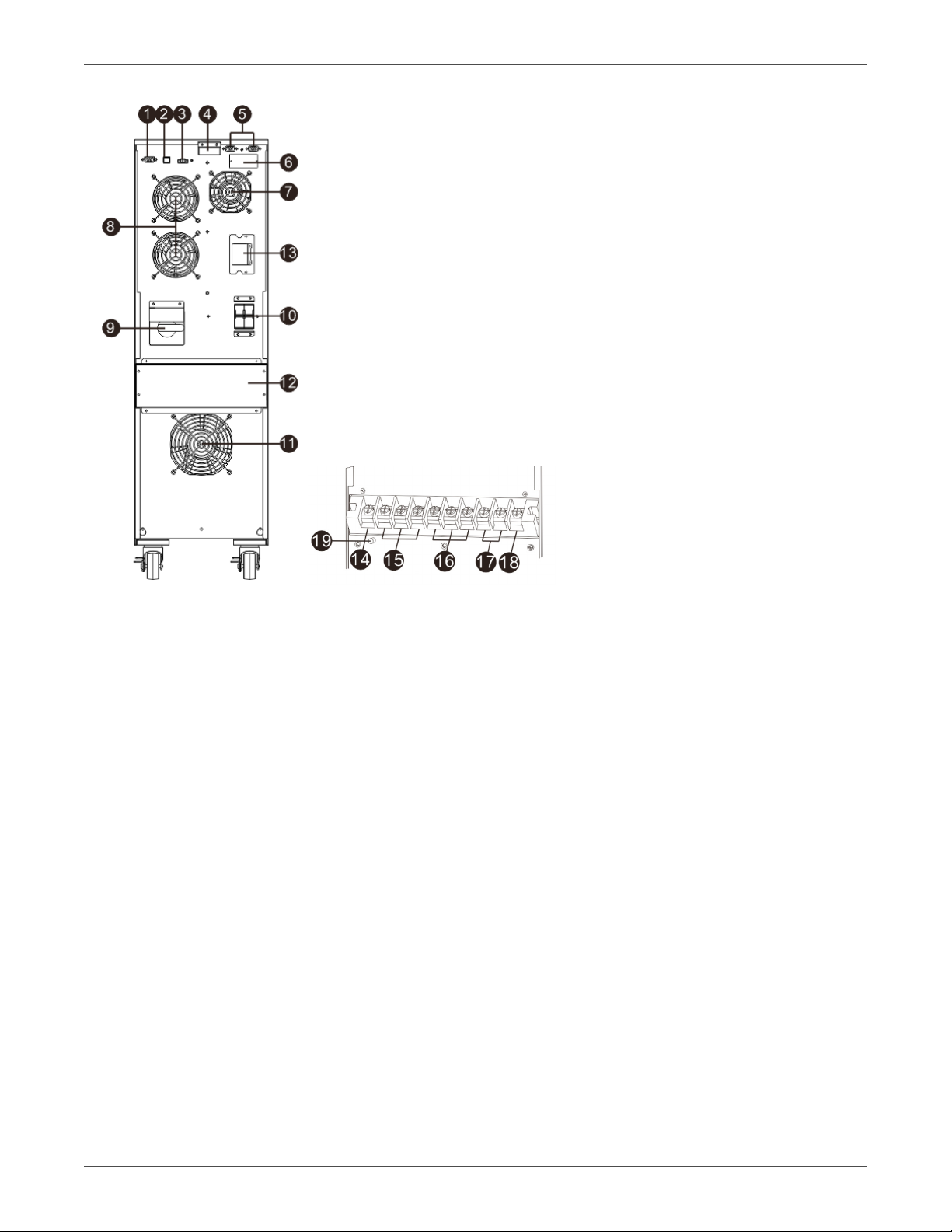
2.2 Rear Panel View
Diagram 1: Rear Panel Overlook Diagram 2: Input/Output Terminal
1. RS-232 communicaon port
2. USB communicaon port
3. Emergency power o funcon connector (EPO connector)
4. Share current port (only available for parallel model)
5. Parallel port (only available for parallel model)
6. Intelligent slot
7. Charger fan
8. Power stage fan
9. Maintenance bypass switch
10. Input circuit breaker
11. Isolaon transformer fan
12. Input/Output terminal (Refer to Diagram 2 for the details)
13. External baery connector
14. Non-isolated neutral
15. ISO TAP selecons
16. Output
17. Input
18. Input ground
19. Output ground

Xtreme Power Conversion Corporaon
TX91 3.8- 10kVA User’s Manual
Page 9
Uninterrupble Power Supply
2.3 Baery Pack Rear Panel View
TX91-BP20/BP40/BP60 baery pack
Figure 2-4
1. DC connector: connects to either UPS or 2nd baery pack.
2. DC breaker: Baery over-current protecon breaker.

Xtreme Power Conversion Corporaon
TX91 3.8- 10kVA User’s Manual
Page 10
Uninterrupble Power Supply
2.4 UPS Electrical Connecons/Installaon
Installaon and wiring must be performed in accordance with the local electric laws/regulaons and execute the
following instrucons by professional personnel.
1. Make sure the mains wire and breakers in the building are sized for the rated capacity of UPS to avoid
the hazards of electric shock or re.
2. Switch o the mains switch in the building before installaon.
3. Turn o all the connected devices before connecng to the UPS.
4. Prepare wiring based on the following table:
Model Wiring spec (AWG)
Input Output Non-isolated
Neutral
Ground
3.8K 8 8 8 8
5K 8 8 8 8
6K 6 6 6 6
10K 4444
Model Recommended Input Overcurrent Protecon
3.8K 30A
5K 30A
6K 40A
10K 70A
NOTE: The selecons for size and color of wires should follow the local electrical laws and regulaons.
5.Remove the terminal block cover on the rear panel of UPS
UPS Terminal Block Wiring Diagram UPS Transformer Diagram
Figure 2-3 Figure 2-4
1. Connect input L1 wire to UPS input L1 terminal.
This manual suits for next models
1
Table of contents
Other Xtreme UPS manuals


 Plus Startup manual")


