Yale Doorman L3 User manual

1
Installation
instructions

2
Congratulations on your new Yale Doorman L3 smart lock!
Please read these instructions with care to ensure the easy and correct installation and
operation of the product. In this manual, we will explain how to safely install the product on
your door.
The Yale Doorman L3 smart lock can be used with the Yale Home mobile app or without
the app by using the lock’s keypad and other buttons. Instructions for both use cases are
included in a later section of the manual.
For remote management and connecting your lock to various smart home and voice control
systems, you can purchase the Yale Connect Wi-Fi Bridge accessory for your Yale Doorman
L3 smart lock.
Proceed to the next page to start exploring the product and preparing for its installation by
checking that the installation location requirements are met.
Hereby ABLOY OY declares that the radio equipment type
Yale Doorman L3, F4, Smart Lock is in compliance with
Directive 2014/53/EU. The full text of the EU declaration of
conformity is avail-able at the following internet address:
abloy.fi/doc
RFID
Max radio power: -34.93 dBA/m
Frequency: 13.56 MHz
BLE
Max radio power: -1.30 dBA/m
Frequency: 2412 – 2462 MHz
3
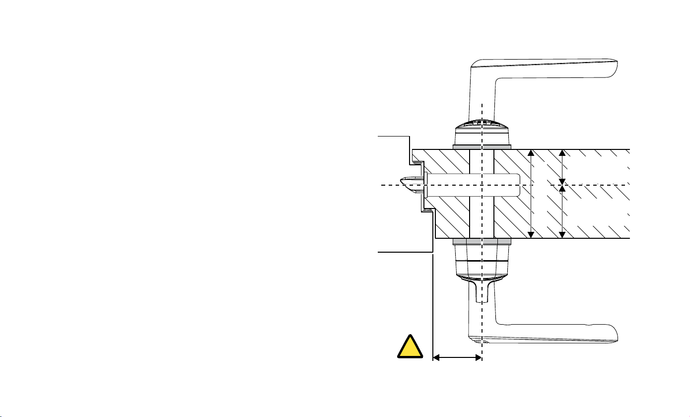
INSTALLATION LOCATION REQUIREMENTS
!Min.
29 mm
Outside
Inside
• The BL907 lock body included in the package can replace
the following lock bodies: ABLOY 4190, LC100, LC102,
and LC190. If you are installing the lock on a fire door,
you must consult the door’s manufacturer to verify that
the door’s fire rating is retained with the Yale Doorman L3
smart lock. In this case, the lock must be installed with
the separate fire door kit.
• Check that there is sufficient space available on the
inside of the door. The recommended minimum distance
between the door frame and the centre of the current
handle is 29 mm. The lock may impact the door frame
when the door is used if the distance is less than 29 mm.
• Note the operating temperature: +5...+50 °C on the inside
(dry) and -25...+70 °C on the outside.
Min. 16 mm
Max. 33 mm
Min. 17 mm
Max. 79 mm
Max. 100 mm
4
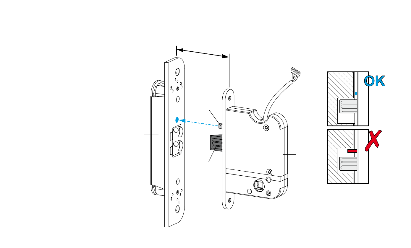
Strike
plate
Lock
body
Bolt
Trigger
bolt
1.55.5 mm
INSTALLATION LOCATION REQUIREMENTS
• The distance between the
door and the strike plate must
be between 1.5 and 5.5 mm.
If the gap is wider than 5.5
mm, the lock may not work
reliably. Adjust the door or the
strike plate to reduce the gap,
if necessary.
• The trigger bolt must not slip
into the strike plate’s opening.
Replace or adjust the strike
plate, if necessary.
5
Tools required for installation:
• PH2 crosshead screwdriver
• T20 Torx screwdriver
• Hex key
• Measuring tape
• Bolt cutter or hacksaw
• DO NOT USE POWER
TOOLS WITH
INSTALLATION!
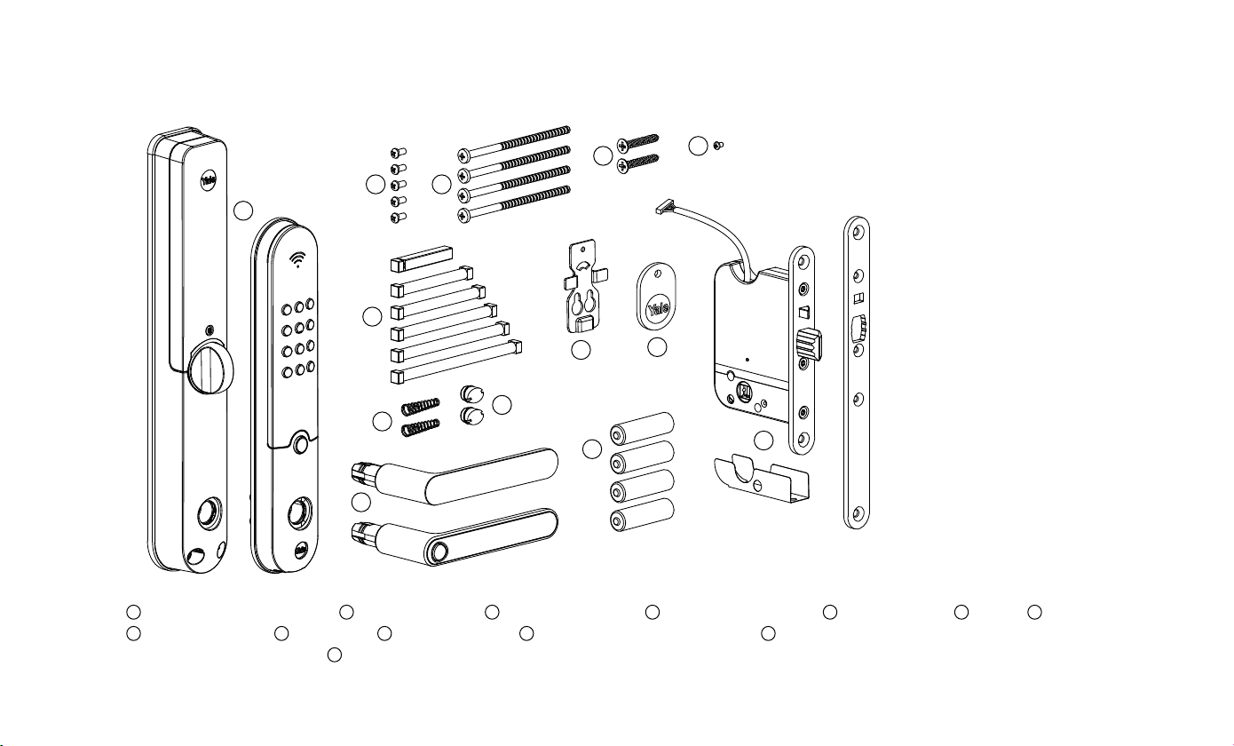
PACKAGE CONTENTS
1Outside and inside units 25 M4×8 screws 34 snap-off screws 42 wood screw 4x25 51 small screw 66 pins 72 springs
822 rubber plugs 92 handles 10 1 support plate 11 1 Desfire-access control tag 12 4 AA batteries (replace after four months
from date of installation) 13 1 lock body
1
2 3
5
6
7
8
9
10 11
12 13
4

6
We recommend that you connect your Yale Doorman L3 smart lock to our free
Yale Home mobile app. The app is an easy way to manage your lock and offers
many useful features, such as locking delay adjustment, automatic opening, and
remote control*. The app also includes the product’s installation instructions in
video format. The app is free to use.
How to use your lock with the Yale Home app:
1Take a moment before you install your lock!
2Download the free Yale Home mobile app from your phone’s app store.
3Open the app and create an account to log in.
4Connect the lock to the app by opening the app menu and selecting “add new
device”.
5Follow the in-app instructions. You can now view videos on your phone for clear
instructions on how to install and start using your lock.
If you would prefer to use your smart lock without the Yale Home app, skip to
page 8 for smart lock installation instructions.
* The Yale Connect Wi-Fi Bridge accessory is required for remote lock control.
BEFORE YOU CONTINUE

7
PREPARE THE INSTALLATION
Onefit
Note the model and handing of your door’s current lock body.
Compare the bolts and latches of your current lock body to those of
the BL907 and change its handing, if necessary. Replace the face
plate with the Onefit model, if necessary.
Old lock body
ABLOY 4190 or LC100: use the short face plate.
ABLOY LC190 or LC102: use the long Onefit face plate.
Avoid overtightening the screws – excessive force may damage the
lock body’s screw threads!
If the old lock body is not listed above, the door may need to
be modified and the installation will therefore differ from these
instructions. In this case, we recommend that you use your local
Abloy-authorised Yale Partner for installation. Visit yale.fi to find your
nearest local partners.

8
1 2 3
4 5 6
1
2
CHANGING THE HANDING OF THE LOCK BODY
Side selection: Remove the anti-drill shield. Remove the side selection screw
and reinstall it on the inside (Figures 1 and 2). The screw-side handle is always
operated mechanically. Avoid overtightening the screw!
CHANGING THE FACE PLATE
Change the face plate, if necessary.

9
Left-handed installation
! !
PREPARE THE INSTALLATION
Check the handing of your door by viewing it from the outside. Keep the handle uninstalled for now.
Prepare the outside unit according to your door’s handing by installing an M4×8 screw as pictured.
Right-handed installation

10
73 mm (K = 17 – 31 mm)
85 mm (K = 31 - 43 mm)
97 mm (K = 43 - 55 mm)
109 mm (K = 55 - 67 mm)
121 mm (K = 67 - 79 mm)
K
A inside handle
B outside handle
PREPARE THE HANDLES
Open the package and find both handles and their spindles. Measure
distance K as pictured from the centre of the lock body to the inside surface
of the door. Select the correct spindle size for the inside handle according
to K.
1Select the spindle size of the inside handle (A) according to distance K.
Note: the handle with a button is the inside handle.
2The outside handle (B) uses a square spindle.
3Note the necessary springs and their correct orientation for installation.
4Set the handles aside to await final installation.
Table of contents
Other Yale Door Lock manuals

Yale
Yale 4600CL Series User manual

Yale
Yale SCP400 Series User manual

Yale
Yale YDG413A User manual

Yale
Yale Real Living YRD156 Technical specifications

Yale
Yale Doorman User manual

Yale
Yale YDM2107 User manual

Yale
Yale Assure Lock 2 Plus User manual

Yale
Yale P-DL01 User manual

Yale
Yale Smart Latch 2 User manual

Yale
Yale Assure Lock YRC256 Technical specifications

Yale
Yale GATEMAN YDM 3109 User manual

Yale
Yale Doorman User manual

Yale
Yale YSSL10 User manual

Yale
Yale YDD120 User manual

Yale
Yale Conexis L1 User manual

Yale
Yale Assure Lock 2 Touch User manual

Yale
Yale Real Living YRD210-ZB Technical specifications

Yale
Yale YDG313 User manual

Yale
Yale YRD210 Technical specifications

Yale
Yale 2310BC Series User manual


