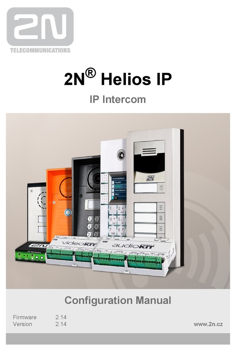
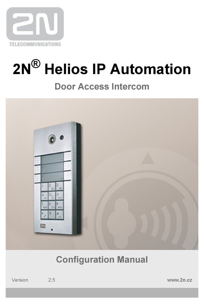
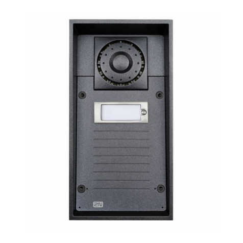
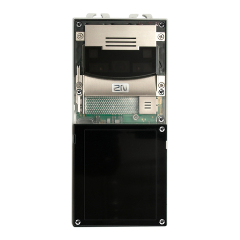
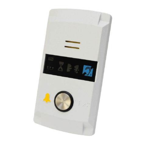
2N Helios IP Force User manual

2N®Helios IP Force
Door Access Intercom
Installation Manual
Version 1.0.0 www.2n.cz

The 2N TELEKOMUNIKACE a.s. joint-stock company is a Czech manufacturer and supplier
of telecommunications equipment.
The product family developed by 2N TELEKOMUNIKACE a.s. includes intercoms, GSM and
UMTS products, private branch exchanges (PBXs) and M2M solution.
2N TELEKOMUNIKACE a.s. has been ranked among the Czech top companies for years
and represents a symbol of prosperity in the field of IP intercoms. Furthermore, the
company dedicates significant attention to operator solutions as well as to effectively
providing support for our distribution network and customer service. At present, we
export our products into over 120 countries worldwide and have exclusive distributors on
all continents.
2Nis a registered trademark of 2N TELEKOMUNIKACE a.s.. Any product and/or other
names mentioned herein are registered trademarks and/or trademarks or brands
protected by law.
2N TELEKOMUNIKACE administers the FAQ database to help you quickly find information
and to answer your questions about 2N products and services. On faq.2n.cz you can find
information regarding products adjustment and instructions for optimum use and
Declaration of Conformity
2N TELEKOMUNIKACE a.s. hereby declares that the 2NHelios IP Force product complies
with all basic requirements and other relevant provisions of the 1999/5/EC directive. For
the full wording of the Declaration of Conformity see the CD-ROM enclosed and at www.2n.cz.
2N TELEKOMUNIKACE company is the owner of the ISO 9001:2008 certificate. All
development, production and distribution processes of the company are managed by this
standard and guarantee high quality, technical level and professional aspect of all our
products.

Contents
1. Product Overview...............................................................5
1.1 Product Description....................................................................................................... 7
Basic Features.................................................................................................................. 7
Advantages of Use........................................................................................................... 8
1.2 Upgrade........................................................................................................................... 9
1.3 2N®Helios IP Force Components and Associated Products................................... 10
Basic Units...................................................................................................................... 10
Flush Mounting Box........................................................................................................ 11
GSM / UMTS Connection Accessories .......................................................................... 11
VoIP Connection Accessories........................................................................................ 12
Electric Locks ................................................................................................................. 12
Other Accesories............................................................................................................ 12
1.4 Terms and Symbols ..................................................................................................... 13
Symbols.......................................................................................................................... 13
2. Description and Installation............................................14
2.1 Before You Start........................................................................................................... 15
Product Completeness Check........................................................................................ 15
2.2 Mechanical Installation................................................................................................ 16
Mounting Type Overview................................................................................................ 16
Common Mounting Principles ........................................................................................ 18
Flush Mounting –Classic Bricks .................................................................................... 19
Flush Mounting –Thermally Insulated Wall................................................................... 20
Flush Mounting –Hollow Bricks..................................................................................... 21
Flush Mounting –Plasterboard ...................................................................................... 21
Wall Mounting................................................................................................................. 22
Use of Cable Bushings................................................................................................... 23
2.3 Electric Installation ...................................................................................................... 24
PCB Connectors............................................................................................................. 24
Configuration Jumpers ................................................................................................... 26
Mounting Completion ..................................................................................................... 27
2.4 Button Tags –Insertion and Replacement ................................................................ 28
Tag Printing.................................................................................................................... 28
Tag Inserting / Replacing Instructions............................................................................ 28
3. Function and Use.............................................................29
3.1 2N®Helios IP Force Configuration ............................................................................. 31
3.2 2N®Helios IP Force Control ........................................................................................ 33
Speed Dial Buttons......................................................................................................... 33
Calling to Telephone Directory Positions ....................................................................... 33
Calling to Telephone Number......................................................................................... 33
Answering and Rejecting Incoming Calls....................................................................... 33
Door Opening (Switch Activation) by Code.................................................................... 34
User / Profile Activation and Deactivation...................................................................... 34
3.3 Maintenance.................................................................................................................. 35
Cleaning ......................................................................................................................... 35
Future Tag Replacement, Programming Changes ........................................................ 35
4. Technical Parameters......................................................37
4.1 Technical Parameters .................................................................................................. 39
5. Supplementary Information ............................................41
5.1 Directives, Laws and Regulations .............................................................................. 42
5.2 Troubleshooting........................................................................................................... 43
5.3 General Instructions and Cautions ............................................................................ 44
Electric Waste and Used Battery Pack Handling ........................................................... 45

5
1
1. Product
Overview
In this section, we introduce the 2N®Helios IP Force product, outline its application
options and highlight the advantages following from its use.
Here is what you can find in this section:
Product Description
Upgrade
2NHelios IP Force Components and Associated Products
Terms and Symbols


7
1.1 Product Description
Basic Features
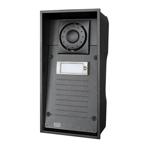
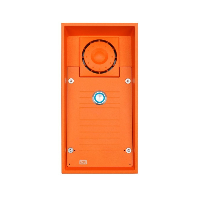
2N®Helios IP Force is a highly resistant and reliable IP door access intercom
provided with a lot of useful above-standard functions. Supporting the SIP standard
and being compatible with the leading IP PBX and telephone suppliers, 2NHelios IP
Force can make use of all VoIP services. 2NHelios IP Force can work as a standard
or emergency door access intercom for buildings, entrances to premises or garages,
manufacturing halls, highways and so on.
2N®Helios IP Force is equipped with two very sensitive microphones and an up to
10W loudspeaker. Thanks to an integrated acoustic echo cancelling (AEC) system, the
product provides mutual audibility even of persons talking at the same time under
normal conditions.
2N®Helios IP Force can be equipped with a colour wide-angle camera, which
displays
2N®Helios IP Force can be provided with 1, 2 or 4 pre-programmed buttons. You
can set up to three telephone numbers and time profiles for each of the buttons to
increase the accessibility of the called party.
2N®Helios IP Force can be equipped with a numerical keypad to be used as a code
lock for lock switch activating or telephone/subscriber number dialling.
2N®Helios IP Force is equipped with an electric lock switch. You can control the
switch using a numerical keypad or, during a call, using any telephone set. An
additional switch module can be installed if necessary. A wide range of settings allow
for a variety of applications.
2N®Helios IP Force can also be provided with RFID card reader modules.
2N®Helios IP Force is very easy to install. All you have to do is connect the system
into your LAN via a network cable and feed it from a 12V power supply or your PoE
supporting LAN.
Configure 2N®Helios IP Force using your PC via any web browser. Use the
2N®Helios IP Manager to manage extensive 2NHelios IP Force systems easily and
quickly.

8
Advantages of Use
Uncompromising AntiVandal design
High covering level up to class IP69
Variable mounting options (brick/plasterboard flush mounting, surface
mounting)
Sensitive microphone and powerful loudspeaker
Bidirectional communication acoustic echo cancelling
Integrated colour camera with wide-angle lens
Optional dial buttons including name tags and backlight
Optional numerical keypad with backlight
Integrated electronic lock switches with wide setting options
Optional integrated RFID card reader module
LAN (PoE) or external 12V power supply
Configuration via web interface or dedicated PC application
SIP 2.0 support
Up to 999 telephone directory positions
Up to 20 user time profiles
Video codecs (H.263+, H.264, MPEG-4, JPEG)
Audio codecs (G.711, G.729)
HTTP server for configuration
SNTP client for time synchronisation with server
RTSP server for video streaming
SMTP client for e-mail sending
TFTP client for automatic configuration and firmware update

9
1.2 Upgrade
The manufacturer reserves the right to modify the product in order to improve its
qualities.
Version
Changes

10
1.3 2N®Helios IP Force Components and
Associated Products
Basic Units
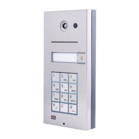
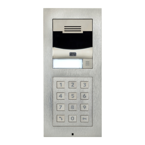
9151101
1 button
9151101C
1 button with
camera
9151101W
1 button, 10W
loudspeaker, IP69
9151101CW
1 button with
camera, 10W
loudspeaker, IP69
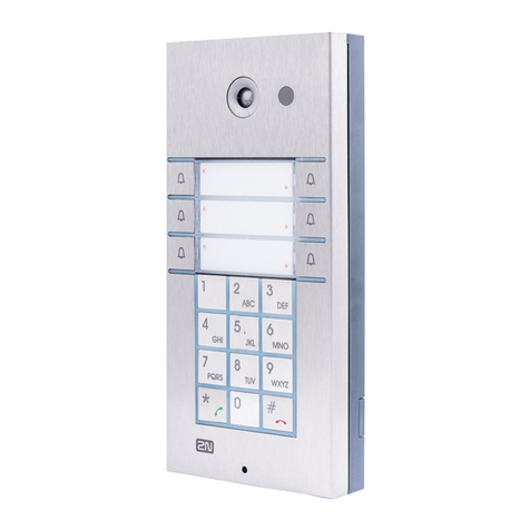
9151104
4 buttons
9151104C
4 buttons with
camera
9151101K
1 button with
keypad
9151101CK
1 button with
keypad and camera
2NHelios IP Force is designed for outdoor applications and requires no additional roof. W-
including Part Nos. are intended for WAP pressure cleaning and extremely noisy
environments (such as highways, etc.).
All 2NHelios IP Force units can be flush or wall mounted without requiring any additional
accessories. Use the appropriate mounting box (see below) for plasterboard and hollow brick
flush mounting.

11
Flush Mounting Box
9151001
Brick flush mounting
box
9151002
Plasterboard flush
mounting box
GSM / UMTS Connection Accessories
505004
2NVoiceBlue Lite
505214
2NVoiceBlue Enterprise
505612
2NUMTS Office Route

12
VoIP Connection Accessories
91378100
PoE injector
91378300
Grandstream VoIP telephone
91378350
Grandstream VoIP video
telephone
Electric Locks
932070
BEFO 1211 12V / 600 mA
932080
BEFO 1221
with momentary pin
932090
BEFO 1211MB
with mechanical blocking
Other Accesories
91341481E
12 V/2 A adapter
A stabilised power supply
must be used where PoE
supply is not applied.
932928E
12 V transformer
9137410E
External IP relay

13
1.4 Terms and Symbols
Symbols
Safety Warning
Always abide by this information to prevent injury of persons!
Warning
Always abide by this information to prevent damage to the device.
Caution
Important information for system functionality.
Tip
Useful advice.
Note
Additional information.

14
2
2. Description and
Installation
In this section we describe the 2N®Helios IP Force product and its installation.
Here is what you can find in this section:
Before You Start
Mechanical Installation
Button Tags Insertion and Replacement
Electric Installation

Before You Start
2.1
15
2.1 Before You Start
Product Completeness Check
Please check the contents of your 2NHelios IP Force delivery:
1 2NHelios IP Force (selected model)
1 frame (of the corresponding colour)
1 Torx 10 / Torx 20 double-ended wrench
Bushings (enclosed):
1 big two-hole sealed bushing with nut
1 spare sealing for big bushing for a thick cable, one hole
1 big blank with nut
1 small bushing with nut
1 bushing plug, big size
2 bushing plugs, small size
1 2NHelios IP Force Installation Manual
1 mounting template
1 CD
1 A5 transparent name plate foil
1 spare name tag
4 5x90 mm screws
4 8x50 mm dowels

Mechanical Installation
2.2
16
2.2 Mechanical Installation
Mounting Type Overview
Refer to the table below for a list of mounting types and necessary components.
Flush mounting –classic bricks
What You Need:
A precisely cut hole or, optionally, the brick
flush mounting box, Part No. 9151001
Flush mounting –thermally insulated wall
What You Need:
Longer screws (depending on the thermal
insulation thickness)
Flush mounting –hollow bricks
What You Need:
Brick flush mounting box, Part No. 9151001

Mechanical Installation
2.2
17
Flush mounting –plasterboard wall
What You Need:
Plasterboard flush mounting box, Part No.
9151002
Wall mounting (concrete and steel
structures, entry barrier columns, etc.)
What You Need:
Just your 2N®Helios IP Force unit (the
covering frame is not applied)
Caution
The warranty does not apply to the product defects and failures arisen as
a result of improper mounting (in contradiction herewith). The
manufacturer is neither liable for damages caused by theft within an area
that is accessible after the attached electric lock is switched. The product
is not designed as a burglar protection device except when used in
combination with a standard lock, which has the security function.
When the proper mounting instructions are not met, water might get in
and destroy the electronics. It is because the intercom circuits are under
continuous voltage and water infiltration causes an electro-chemical
in this way!

Mechanical Installation
2.2
18
Common Mounting Principles
Tips
Select flush mounting where possible to make your product elegant
looking, more vandal resistant and more secure.
You can purchase the flush mounting box in advance and hire an
installation professional to make the basic installation work. Moreover, the
mounting box helps you align the intercom vertically (with a deviation of
up to
Caution
Make sure that the dowel holes have the required diameter. If the
diameter is too large, the dowels may get loose. Use some suitable
building adhesive to keep the dowels in place.
Make sure that the hole depth is sufficient too! The dowel length is 50 mm
and the screw length is 90 mm.
Remember that dowels of poor quality may easily get loose and fall out of
the wall!
Stainless steel screws are used for the 2NHelios IP Force assembly.
Other screws than stainless steel ones corrode soon and may aesthetically
deteriorate the surrounding environment!
Having removed the front panel, make sure that no dirt gets inside the
product (especially onto the sealing surface and microphone sound
guides).
Note
The microphone sound guides are normally loose after the front panel is
removed! The screw is only used as a fall-out protection during
installation.

Mechanical Installation
2.2
19
Flush Mounting –Classic Bricks
If you use the brick flush mounting box, follow the instructions included in the box. If
you do not use the mounting box, follow the instructions below:
1. Make a hole using the template.
Suppose that all the required
cables have been carried into
the hole.
2. Unpack the frame, put the
intercom inside and place the
set onto the hole to make sure
that the hole is deep enough
and the uneven edge is
perfectly covered with the
frame.
3. Push or hammer the enclosed
dowels into the drilled holes.
Use some suitable building
adhesive if the dowels are too
loose.
4. Remove the front panel from
the intercom. The electronic
parts of the two bottom buttons
remain on the panel in the four-
name plate version.
5. Select the holes for cable
supply. Insert the blanks into
the other holes. Apply the cable
bushings or a suitable sealant to
prevent penetration of insects
or water. You can also insert the
small bushing in the intercom
bottom hole.
6. Put the frame on the intercom.
7. Place the intercom into the hole
while introducing the cables.
Leave some of the cables inside
the unit as a reserve and the
rest under the intercom bottom.
8. Insert the enclosed screws in
the lateral mounting holes making sure they have penetrated into the dowels.
Tighten all the screws properly. Tip: The screw tightening sequence may affect the
intercom position.
9. You can seal the frame - wall gap with a silicone or another sealant to avoid wall
dampening as a result of water leakage. This additional sealing is unnecessary for
the intercom function.
10. Do not complete mounting until you have finished electrical installation refer to
Mounting Completion
make sure that
the dowel holes are
drilled accurately!
You will not be able
to align considerable
inaccuracies with this
way of mounting!

Mechanical Installation
2.2
20
Flush Mounting –Thermally Insulated Wall
Cut out the thermal insulation layer using the template (the same as for classic brick
wall).
Caution
The hole depth depends on the insulation layer thickness. If the insulation
layer is rather thick, you may need longer screws! If there are hollow
bricks under the insulation, make sure that your screws pass through the
whole dowel (50 mm) and fix the dowel reliably.
Make sure that the dowel holes have the required diameter. If the
diameter is too large, the dowels may get loose. Use some suitable
building adhesive to keep the dowels in place.
Make sure that the hole depth is sufficient too! The dowel length is 50 mm
and the screw length is 90 mm.
Suppose that all the required cables have been carried into the drilled hole. Now follow
the instructions applicable for classic brick flush mounting. However, remember that
thermally insulated walls show less strength than classic brick walls.
Other manuals for Helios IP Force
3
Table of contents
Other 2N Intercom System manuals