manuals.online logo
Brands
  1. Home
  2. •
  3. Brands
  4. •
  5. 3One data
  6. •
  7. Switch
  8. •
  9. 3One data IPS316-2GC-4POE User manual

3One data IPS316-2GC-4POE User manual

IPS316-2GC-4POE
Unmanaged Industrial PoE Ethernet
Switch Quick Installation Guide
3onedata Co., Ltd.
Address:
3/B, Zone 1, Baiwangxin High Technology
Industrial Park, Xili, Nanshan District,
Shenzhen
Website:
www.3onedata.com
Tel:
+86 0755-26702688
Fax:
+86 0755-26703485
【Package Checklist】
Please check whether the package and accessories are intact
while using the switch for the first time.
1.
Industrial Ethernet switch
2.
Certification
3.
Quick installation guide
4.
Warranty card
5.
DIN-Rail mounting attachment
If any of these items are damaged or lost, please contact our
company or dealers, we will solve it ASAP.
【Product Overview】
The product is unmanaged industrial DIN-Rail PoE Ethernet
switch. The model is: IPS316-2GC-4POE (2 Gigabit Combo
Ports + 4 100M PoE Copper Ports)
【Panel Design】
Top view, Bottom view and Rear view
Front view and Side view
1. Grounding screw
2. Relay alarm output terminal block
3. Console port (Reserved)
4. Power input terminal block
5. DIP switch
6. DIN-Rail mounting kit
7. Power supply input status indicator P1/P2
8. Relay alarm indicator ALM
9. Device running indicator RUN
10. 100M PoE copper port PoE power supply status
indicator
11. Gigabit SFP slot of Gigabit Ethernet Combo port
12. Ethernet port status indicator
13. Gigabit copper port of Gigabit Ethernet Combo port
14. 10/100Base-T(X) 100M Ethernet PoE copper port
【Mounting Dimension】
Unit: mm
Attention before mounting:
Don't place or install the device in area near water or
moist, keep the relative humidity of the device
surrounding between 5%~95% without condensation.
Before power on, first confirm the supported power
supply specification to avoid over-voltage damaging the
device.
The device surface temperature is high after running;
please don't directly contact to avoid scalding.
【DIN-Rail Mounting】
For convenient usage in industrial environments, the product
adopts 35mm DIN-Rail mounting, mounting steps as below:
Check whether the DIN-Rail mounting kit that
Step 1
comes with the device is installed firmly.
Insert the bottom of DIN-Rail mounting kit (one side
Step 2
with spring support) into DIN-Rail, and then insert
the top into DIN-Rail.
Tips:
Insert a little to the bottom, lift upward and then insert
to the top.
Check and confirm the product is firmly installed on
Step 3
DIN-Rail, and then mounting ends.
【Disassembling DIN-Rail】
Power off the device.
Step 1
After lift the device upward slightly, first shift out the
Step 2
top of DIN-Rail mounting kit, and then shift out the
bottom of DIN-Rail, disassembling ends.
Attention before power on:
Power ON operation: first connect power line to the
connection terminal of device power supply, and then
power on.
Power OFF operation: first unpin the power plug, and
then remove the power line, please note the operation
order above.
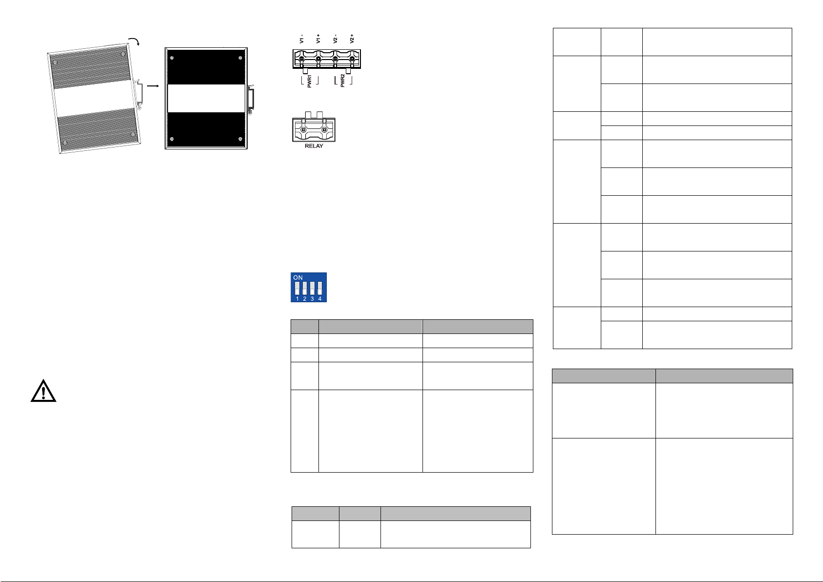
【Power Supply Connection】
DC power supply
The product provides 4 pins power supply input terminal
blocks and two independent DC power supply systems of
PWR1 and PWR2. The power supply
supports anti-reverse connection. Power
supply range: 48VDC.
【Relay Connection】
Relay terminal blocks are a pair of normally
open contacts in the alarm relay of the device.
They are open circuit in the status of normal no
alarm, and closed when any warning message occurs. For
example: they are closed and send out alarm when power off.
The product supports 1 relay warning message output, and
network abnormal alarm output. It can be connected to alarm
indicator, alarm buzzer, or other switching value collecting
devices for timely warning operating staffs when the warning
message occurs.
【DIP Switch Settings】
The product provides 4 pins DIP switch for
function settings, where "ON" is the enable valid
terminal.
DIP switch definitions as follows:
DIP
Definition
Operation
1
Flow control
Set the DIP switch to ON
2
Port alarm
Set the DIP switch to ON
3
Specified 10M of 100 M
copper port
Set the DIP switch to ON
4
VLAN division and
isolation (G2 could
communicate with other
ports but other ports
cannot communicate
with each other)
Set the DIP switch to ON
【Checking LED Indicator】
The function of each LED is described in the table as below:
LED
Status
Description
P1
ON
P1 is connected and running
normally
OFF
P1 is disconnected and running
abnormally.
P2
ON
P2 is connected and running
normally
OFF
P2 is disconnected and running
abnormally
ALM
ON
Port link alarm
OFF
Port link without alarm
RUN
ON
The device is powering on or
abnormal.
OFF
The device is powered off or
abnormal.
Blinking
Blink once per second, the device is
running well.
Link/ACT
(1-4/G1-
G2)
ON
Ethernet port has established valid
connection.
Blinking
Ethernet is in an active network
status
OFF
Ethernet port has not established
valid connection.
PoE+
(1-4)
ON
PoE port is powering other devices.
OFF
PoE port is not connected or PoE
function is not enabled.
【Specification】
Panel
Gigabit Combo port
1000Base-X, optional Gigabit
SFP slot or
10/100/1000Base-T(X) Gigabit
RJ45
100M PoE copper port
10/100Base-T(X) self-adapting
RJ45 port, full/half duplex
self-adaption or specified
operating mode, support
MDI/MDI-X self-adaption; the
greatest output power of single
PoE port is 30W
PoE power supply pin
V+, V+, V-, V- correspond to 1,
2, 3, 6
Console port
(Reserved)
Alarm interface
2 pins 7.62mm pitch terminal
blocks, support 1 channel relay
alarm information output, current
loading ability is 1A@24VDC or
0.5A@120VAC
Indicator
Power indicator, running
indicator, interface indicator,
alarm indicator and PoE+
indicator
Exchange attributes
Backplane bandwidth
7.6G
Packet buffer size
1Mbit
MAC table size
8K
Power supply
Input power supply
48VDC, dual power supply
redundancy, anti-reverse
connection
Access terminal
4 pins 7.62mm pitch terminal
blocks
Consumption
No-load
7.9W@48VDC
Full-load
113.4W@48VDC
Environmental Limits
Working temperature
-40~75℃
Storage temperature
-40~75℃
Working humidity
5%~95% (no condensation)
Protection grade
IP40 (metal shell)

Other 3One data Switch manuals

3One data IES3016L Series User manual

3One data

3One data IES3016L Series User manual

3One data IES5028-4GS-2F User manual

3One data

3One data IES5028-4GS-2F User manual

3One data IES1028 Series User manual

3One data

3One data IES1028 Series User manual

3One data TNS5500 Series User manual

3One data

3One data TNS5500 Series User manual

3One data PS5026G-2GS-24PoE User manual

3One data

3One data PS5026G-2GS-24PoE User manual

3One data IPS7112G-4GS-8GPOE User manual

3One data

3One data IPS7112G-4GS-8GPOE User manual

3One data IES6210 Series User manual

3One data

3One data IES6210 Series User manual

3One data IPS215-4POE User manual

3One data

3One data IPS215-4POE User manual

3One data IES615-2DI(3IN1) Series User manual

3One data

3One data IES615-2DI(3IN1) Series User manual

3One data MES600 Series User manual

3One data

3One data MES600 Series User manual

3One data ICS5428 Series User manual

3One data

3One data ICS5428 Series User manual

3One data ES1026-2F User manual

3One data

3One data ES1026-2F User manual

3One data IES6300PRO Series User manual

3One data

3One data IES6300PRO Series User manual

3One data IPS7110-2GC-8POE User manual

3One data

3One data IPS7110-2GC-8POE User manual

3One data IPS215 Series User manual

3One data

3One data IPS215 Series User manual

3One data IES615-2DI Series User manual

3One data

3One data IES615-2DI Series User manual

3One data IES6200-PN-16T4GS-2P48 User manual

3One data

3One data IES6200-PN-16T4GS-2P48 User manual

3One data IES6300 Series User manual

3One data

3One data IES6300 Series User manual

3One data IES2220 Series User manual

3One data

3One data IES2220 Series User manual

3One data ICS6400-12GT12GS4XS User manual

3One data

3One data ICS6400-12GT12GS4XS User manual

3One data IES6306 Series User manual

3One data

3One data IES6306 Series User manual

3One data TNS5000D Series User manual

3One data

3One data TNS5000D Series User manual

3One data IPS7110 Series User manual

3One data

3One data IPS7110 Series User manual

3One data ICS6420 Series User manual

3One data

3One data ICS6420 Series User manual

Popular Switch manuals by other brands

Emcotec RC Electronic SPS-RCS quick start guide

Emcotec

Emcotec RC Electronic SPS-RCS quick start guide

Avaya C360 Manager Quick start for hardware installation

Avaya

Avaya C360 Manager Quick start for hardware installation

Barksdale D1T operating instructions

Barksdale

Barksdale D1T operating instructions

IOGear GCMS1922 user manual

IOGear

IOGear GCMS1922 user manual

AVCOMM 608TX Quick installation guide

AVCOMM

AVCOMM 608TX Quick installation guide

Opencockpits B737 Installation & user manual

Opencockpits

Opencockpits B737 Installation & user manual

Altronix HubWay8DS installation guide

Altronix

Altronix HubWay8DS installation guide

KTI Networks KS-116 Specification sheet

KTI Networks

KTI Networks KS-116 Specification sheet

WIKA A2G-45 operating instructions

WIKA

WIKA A2G-45 operating instructions

TERZ NITE-XS installation manual

TERZ

TERZ NITE-XS installation manual

Digitus DS-16202-1 user manual

Digitus

Digitus DS-16202-1 user manual

IDK FDX-16 Command reference guide

IDK

IDK FDX-16 Command reference guide

HP PROCURVE 2910AL Access security guide

HP

HP PROCURVE 2910AL Access security guide

Gefen EXT-DVIKVM-441DL user manual

Gefen

Gefen EXT-DVIKVM-441DL user manual

ATEN VanCryst VS0801A Quick start guides

ATEN

ATEN VanCryst VS0801A Quick start guides

Monoprice 611680 user manual

Monoprice

Monoprice 611680 user manual

IP Power 9258 user manual

IP Power

IP Power 9258 user manual

Kohler RSB Series Operation

Kohler

Kohler RSB Series Operation

manuals.online logo
manuals.online logoBrands
  • About & Mission
  • Contact us
  • Privacy Policy
  • Terms and Conditions

Copyright 2025 Manuals.Online. All Rights Reserved.