manuals.online logo
Brands
  1. Home
  2. •
  3. Brands
  4. •
  5. 3One data
  6. •
  7. Switch
  8. •
  9. 3One data IES1024 Series User manual

3One data IES1024 Series User manual

IES1024 Series
Unmanaged Industrial
Ethernet Switch
Quick Installation Guide
3onedata Co., Ltd.
Address:
3/B, Zone 1, Baiwangxin High Technology
Industrial Park, Song Bai Road, Nanshan
District, Shenzhen, 518108, China
Website:
www.3onedata.com
Tel:
+86 0755-26702688
Fax:
+86 0755-26703485
【Package Checklist】
Please check the integrity of package and accessories while
first using the switch.
1.
Industrial Ethernet switch x 1
2.
Terminal block
3.
Power line (AC products)
4.
Mounting lug
5.
Quick installation guide
6.
Foot pad
7.
Certification
8.
Warranty card
If any of these items are damaged or lost, please contact our
company or dealers, we will solve it ASAP.
【Product Overview】
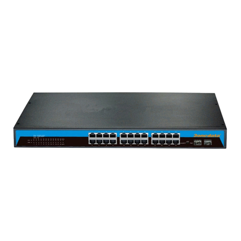
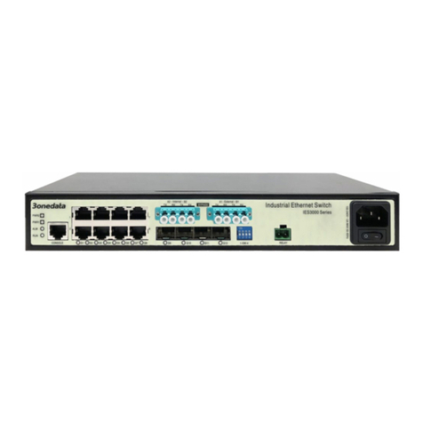
This series of products are 24-port 100M layer 2
rack-mounted unmanaged industrial Ethernet switches.
Models include:
Model I. IES1024 (24 100M copper ports)
Model II. IES1024-2F (22 100M copper ports + 2 100M fiber
ports)
Model III. IES1024-4F (20 100M copper ports + 4 100M fiber
ports)
Model IV. IES1024-8F (16 100M copper ports + 8 100M fiber
ports)
Model V. IES1024-12F (12 100M copper ports + 12 100M
fiber ports)
Model VI. IES1024-16F (8 100M copper ports +16 100M
fiber ports)
Model VII. IES1024-20F (4 100M copper ports + 20 100M
fiber ports)
Model VIII. IES1024-24F (24 100M fiber ports)
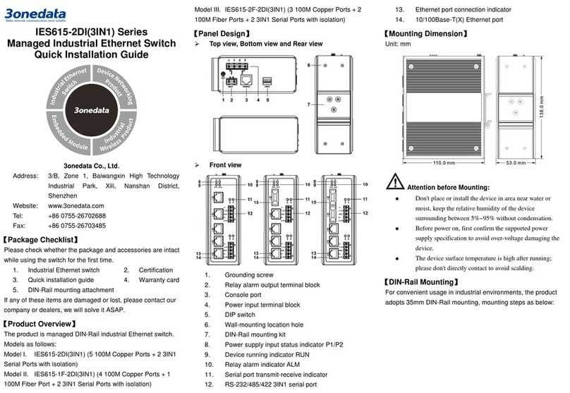
【Panel Design】
Front view
Rear view
Top view
Left view
Right view
1. Restore factory defaults button (reserved)
2. Console port (reserved)
3. Ethernet port connection indicator
4. Device running status indicator RUN
5. Power supply input status indicator PWR
6. Relay alarm status indicator ALM
7. Rack mounting lug
8. Power input terminal block
9. Relay output terminal block
10. 100M copper port
11. Ethernet port connection indicator
12. 100M fiber port
【Mounting Dimension】
Unit: mm
Attention before mounting:
Don't place or install the device in moist area or near
water, keep the relative humidity of the device
surrounding between 5%~95% without condensation.
Before power on, first confirm the supported power
supply specification to avoid over-voltage damaging the
device.
The device surface temperature is high after running,
please don't directly contact to avoid scalding.
【Installation of Rack-mounted Device】
Step 1 Select the device installation location to reserve
sufficient size.
Step 2 Adopt screws to install the mounting lugs in the
device position as figure below.
Step 3 Place the device in the rack, adopt 4 screws to
install the mounting lugs on the left and right side in
the rack.
Step 4 Check and confirm the product is firmly installed on
the rack, then mounting ends.
【Rack-mounting Device Disassembling】
Step 1 Power off the device.
Step 2 Unscrew the fixing screw of mounting lug on the
rack.
Step 3 Remove the device from the rack, disassembling
ends.
【Power Supply Connection】
This series of devices provide 5 pins 5.08mm pitch terminal
blocks, power supply occupies 3 pins on the left.The power
supply has nonpolarity and anti-reverse function, the device
can be normally working after reverse connection. The pin
definition of power supply as follows:
Pin NO.
1
2
3
Definition
L/+
GND
N/-
Single power supply
This series of products supports single
power supply scheme, power supply
value range is: 100~240VAC/DC.
Dual power supply
This series of products support dual
power supply scheme and provide P1
and P2 independent power supply
systems. When one of the power supply
system fails, the device can operate
uninterruptedly and normally, which has
improved the reliability of network operation. Power supply
value range is: 100~240VAC/DC.
Notes:
Power ON operation: First insert the power supply
terminal block into the device power supply interface,
and then plug the power supply plug contact and power
on.
Power OFF operation: First unpin the power plug, and
then remove the wiring part of terminal block, please
pay attention to the operation order above.
【Relay Connection】
This series of devices provide 5 pins
5.08mm pitch terminal blocks; power
supply occupies 3 pins on the left. Relay
terminals are a pair of normally closed
contacts in device alarm relay. They are open circuit in normal
non alarm state, closed when power off. This series of single
and dual power supply products respectively support 1 or 2
channels relay alarm output and down alarm of power supply.
Dual power supply products will send out alarm when two
power supplies break down. The device can be connected to
alarm indicator, alarm buzzer, or other switching value
collecting device, it can timely inform operator when alarm
occurs. The pin definition of relay as follows:
Pin NO.
4
5
Definition
R+
R-
【Checking LED Indicator】
The device provides LED indicators to monitor the device
working status with a comprehensive and simplified
troubleshooting; the function of each LED is described in the
table as below:
LED
Status
Description
PWR
ON
Power supply is connected and
running normally
OFF
Power supply is disconnected or
running abnormally.
ALM
ON
Reserved
OFF
Reserved
RUN
ON
The device is powering on or
abnormal
OFF
The device isn't powered on or is
abnormal
Blinking
Flash 1 time per second, the device
is running normally.
Link/Act
(1-24)
ON
Ethernet port connection is active.
Blinking
Ethernet port is in network active
status
OFF
Ethernet port connection is inactive
【Specification】
Panel
100M copper port
10/100Base-T(X) self-adapting
RJ45 port, half/full duplex
self-adaption, support
MDI/MDI-X self-adaption
100M fiber port
100Base-FX, optional
SC/ST/FC interface
Alarm interface
5 pins 5.08mm pitch terminal
blocks, including 2 alarm
terminal blocks. Support 1 relay
alarm output, current load
capacity is 5A@30VDC or
10A@125VAC.
Indicator
Power supply indicator, run
indicator, interface indicator,
alarm indicator
Exchange Attributes
Backplane bandwidth
12.8G
Packet buffer size
3Mbit
MAC table size
8K
Power supply
Input power supply
100~240VAC/DC, support
single or dual power supply
scheme, and 8A output
overcurrent protection
Access terminal
5 pins 5.08mm pitch terminal
blocks, including 3 pins power
supply terminal blocks
Consumption
IES1024
No-load: 6.9W@220VAC
Full-load: 9.4W@220VAC
IES1024-2F
No-load: 8.2W@220VAC
Full-load: 10.7W@220VAC
IES1024-4F
No-load: 9.5W@220VAC
Full-load: 12W@220VAC
IES1024-8F
No-load: 12.1W@220VAC
Full-load: 14.6W@220VAC
IES1024-12F
No-load: 14.7W@220VAC
Full-load: 17.2W@220VAC
IES1024-16F
No-load: 17.3W@220VAC
Full-load: 19.8W@220VAC
IES1024-20F
No-load: 18.8W@220VAC
Full-load: 20.7W@220VAC
IES1024-24F
No-load: 21.4W@220VAC
Full-load: 22.9W@220VAC
Environmental Limits
Working temperature
-40~75℃
Storage temperature
-40~75℃
Working humidity
5%~95% (no condensation)
Protection grade
IP30 (metal shell)

This manual suits for next models

6

Other 3One data Switch manuals

3One data IES6220 Series User manual

3One data

3One data IES6220 Series User manual

3One data IES5028-4GS-2F User manual

3One data

3One data IES5028-4GS-2F User manual

3One data IES5024 Series User manual

3One data

3One data IES5024 Series User manual

3One data IES2008 User manual

3One data

3One data IES2008 User manual

3One data IES2305 Series User manual

3One data

3One data IES2305 Series User manual

3One data IES615-2DI(3IN1) Series User manual

3One data

3One data IES615-2DI(3IN1) Series User manual

3One data IPS7110-2GC-8POE User manual

3One data

3One data IPS7110-2GC-8POE User manual

3One data IES215 Series User manual

3One data

3One data IES215 Series User manual

3One data IES5028 Series User manual

3One data

3One data IES5028 Series User manual

3One data IES618 Series User manual

3One data

3One data IES618 Series User manual

3One data IES716-2GS User manual

3One data

3One data IES716-2GS User manual
3One data IES618 Series User manual

3One data

3One data IES618 Series User manual

3One data ICS6400-12GT12GS4XS User manual

3One data

3One data ICS6400-12GT12GS4XS User manual

3One data IES7112G-4GS User manual

3One data

3One data IES7112G-4GS User manual

3One data ICS5400 Series User manual

3One data

3One data ICS5400 Series User manual

3One data IES206 Series User manual

3One data

3One data IES206 Series User manual

3One data ES209G-1GF User manual

3One data

3One data ES209G-1GF User manual

3One data IES2008-8T-P48 User manual

3One data

3One data IES2008-8T-P48 User manual

3One data IES3016 Series User manual

3One data

3One data IES3016 Series User manual

3One data IPS7112G-4GS-8GPOE User manual

3One data

3One data IPS7112G-4GS-8GPOE User manual

3One data IPS716-2GC-4POE User manual

3One data

3One data IPS716-2GC-4POE User manual

3One data IES6100PN-8T-2LV User manual

3One data

3One data IES6100PN-8T-2LV User manual

3One data IPS215 Series User manual

3One data

3One data IPS215 Series User manual

3One data IES7110-2GS Series User manual

3One data

3One data IES7110-2GS Series User manual

Popular Switch manuals by other brands

Dell PowerConnect B-RX Configuration guide

Dell

Dell PowerConnect B-RX Configuration guide

Collingwood Lighting smart CWSHUB2 manual

Collingwood Lighting

Collingwood Lighting smart CWSHUB2 manual

Schwaiger Sew5 a Series Installation information

Schwaiger

Schwaiger Sew5 a Series Installation information

Panasonic FP (ABP8) Specifications

Panasonic

Panasonic FP (ABP8) Specifications

HP ProCurve J4863A brochure

HP

HP ProCurve J4863A brochure

Intellinet KVM 157025 quick start guide

Intellinet

Intellinet KVM 157025 quick start guide

LevelOne GEU-0523 Quick installation guide

LevelOne

LevelOne GEU-0523 Quick installation guide

HiRO ATLAS user manual

HiRO

HiRO ATLAS user manual

Microsonic pmsplus15/CF/A1 operating instructions

Microsonic

Microsonic pmsplus15/CF/A1 operating instructions

GiBiDi F/1-T Connecting Instructions

GiBiDi

GiBiDi F/1-T Connecting Instructions

Foundry Networks FES2402 installation guide

Foundry Networks

Foundry Networks FES2402 installation guide

Lenovo ThinkSystem NE2572 Product guide

Lenovo

Lenovo ThinkSystem NE2572 Product guide

Lindy 38273 Quick install guide

Lindy

Lindy 38273 Quick install guide

NuTone 59W quick guide

NuTone

NuTone 59W quick guide

Hored PS3016S user manual

Hored

Hored PS3016S user manual

VigilLink VL-WP21UP-1 user manual

VigilLink

VigilLink VL-WP21UP-1 user manual

Philips Multimedia Base 6G3B12 Specifications

Philips

Philips Multimedia Base 6G3B12 Specifications

H3C S1200 Series Getting started guide

H3C

H3C S1200 Series Getting started guide

manuals.online logo
manuals.online logoBrands
  • About & Mission
  • Contact us
  • Privacy Policy
  • Terms and Conditions

Copyright 2025 Manuals.Online. All Rights Reserved.