GE AK-50 Series Technical specifications

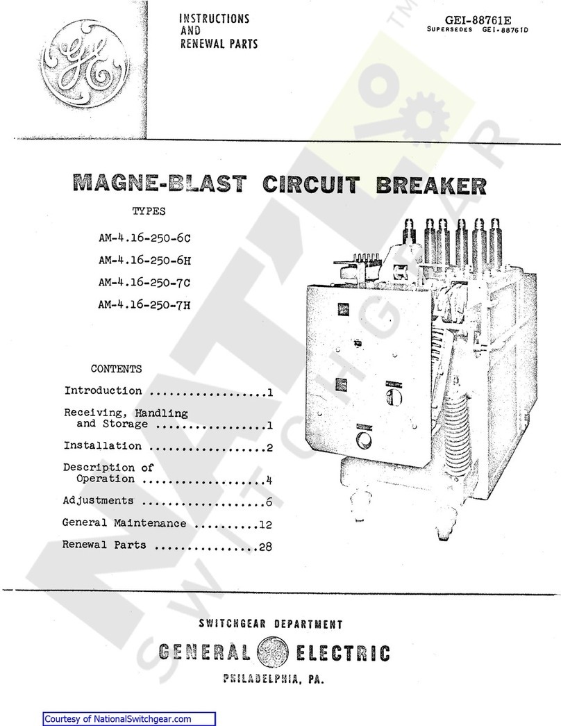
GEK
-
7303
C
*
A
Lowvoltage
Power
Circuit
Breakers
Maintenance
Instructions
'
Supersedes
GEH
-
1798
A
GEH
-
1799
GEH
-
1823
G
El
-
5021
OA
GEI
-
50211
GEI
-
50212
A
GEI
-
57077
G
El
-
74600
Types
AK
-
50
/
75
/
100
,
AKT
-
50
,
AKU
-
50
,
and
AKF
-
2
C
/
2
D
/
2
E
NOTE
:
To
be
used
in
conjunction
with
GEl
-
86135
which
covers
Types
AK
-
75
/
100
breakers
with
ECS
and
SST
trip
devices
.
ELECTRIC
GENERAL
Courtesy of NationalSwitchgear.com

CONTENTS
3
INTRODUCTION
3
OPERATION
MANUAL
CLOSING
.
.
.
MANUAL
MAINTENANCE
CLOSING
OF
ELECTRICAL
BREAKERS
ELECTRICAL
CLOSING
.
QUICK
CLOSE
FOR
ELECTRICAL
BREAKERS
ELECTRICAL
TRIPPING
.
..
3
4
4
4
5
5
MAINTENANCE
INSERTING
SAFETY
PIN
-
AK
-
50
,
AK
-
75
AND
AK
-
100
INSPECTION
TROUBLE
SHOOTING
LUBRICATION
SEPARATION
OF
FRONT
AND
REAR
FRAMES
5
5
6
7
7
7
BASIC
BREAKER
COMPONENTS
ARC
QUENCHERS
POLE
UNIT
ASSEMBLY
OPERATING
MECHANISMS
QUICK
CLOSE
BREAKER
ADJUSTMENTS
AUXILIARY
SWITCH
7
8
13
16
11
23
ELECTRICAL
CLOSING
DEVICES
AND
CONTROLS
CLOSING
SWITCH
CUT
-
OFF
SWITCHES
CONTROL
RELAY
23
23
23
23
PROTECTIVE
DEVICES
STATIC
TIME
DELAY
UNDERVOLTAGE
TRnPING
DEVICE
INSTANTANEOUS
UNDER
VOLTAGE
TRIPPING
DEVICE
.
.
..
UNDERVOLTAGE
LOCKOUT
DEVICE
.
.
.
.
.
.
.
DIRECT
-
ACTING
TRIPPING
DEVICE
-
EC
-
1
B
SERIES
OVERCURRENT
TRIPPING
DEVICE
EC
-
1
SERIES
OVERCURRENT
TRIPPING
DEVICE
EC
-
2
/
EC
-
2
A
.
.
.
REVERSE
CURRENT
TRIPPING
DEVICE
(
AK
-
50
ONLY
)
POWER
SENSOR
TRIP
..
.
.
SELECTIVE
TRIPPING
23
25
25
26
29
31
33
33
39
42
BREAKER
ACCESSORIES
PRIMARY
DISCONNECTS
SECONDARY
DISCONNECTS
DRAWOUT
MECHANISMS
SHUNT
TRIPPING
DEVICE
BELL
ALARM
AND
LOCKOUT
DEVICE
OPEN
FUSE
LOCKOUT
DEVICE
42
42
43
44
44
45
47
MISCELLANEOUS
TOOLS
RENEWAL
’
PARTS
47
47
These
instructions
do
not
purport
to
cover
all
details
or
variations
in
equipment
nor
to
provide
for
every
possible
contingency
to
be
met
in
connection
with
installation
,
operation
or
maintenance
.
Should
further
information
be
desired
or
should
particular
problems
arise
which
are
not
covered
sufficiently
for
the
purchaser
’
s
purposes
,
the
matter
should
be
referred
to
the
General
Electric
Company
.
Courtesy of NationalSwitchgear.com

LOW
-
VOLTAGE
POWER
CIRCUIT
BREAKERS
Types
AK
-
2
/
3
/
2
A
/
3
A
-
50
/
50
S
AKT
-
2
/
3
/
50
/
50
S
AK
-
2
/
3
/
2
A
/
3
A
-
75
/
75
S
AKU
-
2
/
3
/
2
A
/
3
A
-
50
/
50
S
AK
-
2
/
3
/
2
A
/
3
A
-
100
/
100
S
AKF
-
2
C
/
2
D
/
2
E
OPERATION
INTRODUCTION
MANUAL
CLOSING
For
a
description
of
manual
closing
,
refer
to
the
section
of
these
instructions
entitled
CLOS
-
ING
THE
BREAKER
-
MANUALLY
OPERATED
AK
-
50
and
section
entitled
AK
-
50
-
75
AND
-
100
STORED
ENERGY
MANUAL
MECHANISM
,
both
under
OPERATING
MECHANISMS
.
The
instructions
contained
herein
are
intended
to
aid
in
the
maintenance
and
repair
of
basic
breakers
and
accessories
for
AK
-
50
-
75
-
100
Low
Voltage
Power
Circuit
Breakers
.
The
basic
AK
-
50
,
AK
-
75
and
AK
-
100
breaker
designs
have
been
expanded
to
include
special
designs
for
specific
applications
.
These
design
extensions
have
caused
variations
in
the
nomen
-
clature
including
the
following
:
AK
-
2
-
50
,
AK
-
2
-
75
or
AK
-
2
-
100
-
Basic
standard
design
of
breaker
for
stationary
mounting
or
for
drawout
use
in
AKD
type
equipment
.
AK
-
2
A
-
50
,
AK
-
2
A
-
75
,
AK
-
2
A
-
100
-
The
A
indicates
it
has
mounting
features
for
AKD
-
5
type
equipment
.
AK
-
2
-
50
S
,
AK
-
2
-
75
S
,
AK
-
2
-
100
S
-
The
S
indicates
breaker
is
equipped
with
a
quick
-
close
mechanism
which
provides
closing
times
of
approximately
5
cycles
(
.
08
seconds
)
.
AKU
-
2
-
50
fuse
breaker
combination
.
T
_
.
CLOSING
|
“
T
SWITCH
—
—
II
—
11
REMOTE
CLOSE
L
T
*
‘
F
:
|
=
TRIP
I
G
_
IUi
oo
£
C
<
G
±
zF
z
-
i
oo
o
>
L
TRIP
COIL
X
M
LEGEND
*
CLOSING
MOTOR
*
RELAY
COIL
+
*
RELAY
CONTACT
FftG
«
=
MECHANICALLY
OPERATED
SWITCHES
+
=
NORMALLY
OPEN
SWITCH
CONTACTS
£
=
NORMALLY
CLOSED
SWITCH
CONTACTS
L
-
AUXILIARY
SWITCH
CONTACT
®
X
The
U
indicates
an
internal
SIMPLIFIED
ELEMENTARY
DIAGRAM
INTERNAL
WIRING
AK
—
50
,
75
,
AND
100
AKF
-
2
C
,
AKF
-
2
D
,
AKF
-
2
E
switches
for
use
in
controlling
shunt
fields
of
synchronous
motors
and
generators
.
AK
-
2
-
50
H
rupting
rating
has
been
increased
to
the
75
,
000
amp
.
class
.
AK
-
2
-
50
C
,
AK
-
2
-
75
C
-
The
C
indicates
the
interrupting
rating
has
been
increased
to
the
100
,
000
amp
.
class
.
AKT
-
2
-
50
continuous
rating
of
2000
amps
.
AK
-
3
-
50
,
AK
-
3
-
75
,
AK
-
3
-
100
indicates
the
breaker
is
equipped
with
the
Power
Sensor
Overcurrent
Trip
Device
.
AK
-
2
-
50
X
-
The
X
indicates
the
breaker
has
very
special
features
or
it
includes
two
or
more
of
the
design
extensions
previously
described
.
When
contacting
the
factory
,
it
is
important
to
furnish
the
complete
nameplate
information
.
Are
field
Fig
.
1
.
The
H
indicates
the
inter
-
CLOSING
SWITCH
T
J
_
REMOTE
=
F
CLOSE
ih
-
i
.
v
T
-
E
T
-
G
TD
fi
°
o
<
-
»
>
X
±
F
=
TF
=
4
=
X
W
The
T
indicates
increased
\
cc
<
M
)
r
The
3
LEGEND
CC
-
CLOSING
RELAY
COIL
D
-
CLOSING
RELAY
CONTACTS
E
-
ANTI
-
PUMP
RELAY
CONTACTS
FAG
-
MECHANICALLY
OPERATED
SWITCHES
-
AUXILIARY
SWITCH
CONTACTS
-
CLOSING
MOTOR
-
ANTI
-
PUMP
RELAY
COIL
*
-
CONTROL
RELAY
CONTACTS
X
-
CONTROL
RELAY
COIL
4
:
-
NORMALLY
OPEN
SWITCH
CONTACTS
f
-
NORMALLY
CLOSED
SWITCH
CONTACTS
9
SIMPLIFIED
ELEMENTARY
DIAGRAM
INTERNAL
WIRING
QUICK
CLOSE
BREAKER
Fig
.
1
A
.
3
Courtesy of NationalSwitchgear.com

GEK
-
7303
Low
Voltage
Power
Circuit
Breakers
MANUAL
MAINTENANCE
CLOSING
OF
ELECTRICAL
BREAKERS
An
electrical
breaker
may
be
closed
manually
by
means
of
the
maintenance
handle
furnished
with
the
breaker
.
reach
the
fully
charged
position
,
the
mechanically
operated
switches
operate
,
reversing
their
contacts
.
Upon
operation
of
these
switches
the
motor
is
stopped
by
the
opening
of
the
G
switch
.
The
closing
of
the
F
switch
prepares
the
breaker
for
a
closing
operation
.
To
observe
the
operation
of
the
breaker
with
-
out
power
,
with
the
breaker
open
and
springs
discharged
,
proceed
as
follows
:
1
.
Charge
the
closing
spring
with
the
main
-
tenance
handle
(
1
,
Fig
.
3
)
until
the
indica
-
tor
reads
"
charged
”
.
2
.
Continue
to
operate
the
maintenance
handle
until
the
breaker
closes
.
3
.
Open
the
breaker
by
pushing
the
trip
button
(
4
,
Fig
.
2
)
.
ELECTRICAL
CLOSING
The
electrical
control
system
is
comprised
of
an
X
relay
,
two
double
contact
mechanically
operated
switches
(
F
and
G
)
,
a
push
button
closing
switch
and
any
means
for
remote
closing
which
the
user
may
incorporate
into
the
system
.
When
voltage
is
first
applied
to
the
breaker
,
(
before
any
closing
signal
is
given
)
the
motor
is
energized
through
two
of
the
X
relay
contacts
and
the
two
G
switch
contacts
.
The
motor
then
compresses
the
closing
springs
to
the
"
pre
-
charged
"
position
at
which
point
the
mechanically
operated
F
and
G
switches
are
operated
.
This
opens
the
G
contacts
,
stopping
the
motor
,
and
closes
the
F
contacts
,
which
readies
the
system
for
the
actual
closing
of
the
breaker
.
When
the
push
button
or
remote
switch
signals
for
a
closing
operation
,
the
X
relay
coil
is
energized
,
operating
the
X
contacts
.
This
seals
in
the
X
relay
and
energizes
the
motor
once
again
and
the
closing
operation
takes
place
.
QUICK
CLOSE
FOR
ELECTRICAL
BREAKERS
Functionally
,
the
quick
close
mechanism
differs
from
the
standard
electrical
mechanism
in
that
the
pre
-
charge
operation
is
extended
to
completely
charge
the
closing
springs
.
At
the
end
of
the
charg
-
ing
operation
,
which
takes
approximately
5
seconds
,
a
latch
plate
engages
the
prop
roller
to
prevent
the
closing
springs
from
discharging
.
With
the
closing
springs
fully
charged
the
breaker
is
ready
for
a
closing
operation
upon
release
of
the
prop
roller
.
This
may
be
accom
-
plished
either
manually
,
by
depressing
the
closing
lever
on
the
breaker
,
or
electrically
by
closing
the
remote
closing
switch
.
Upon
the
release
of
the
prop
roller
the
closing
springs
discharge
and
close
the
breaker
in
the
same
manner
as
on
the
standard
electrical
breaker
.
Fig
.
2
(
8039671
)
Front
view
of
AK
-
2
-
50
breaker
1
.
Auxiliary
Switch
2
.
Position
Indicator
3
.
Relay
4
.
Manual
Trip
Button
5
.
Shaft
for
Manual
Mainte
-
nance
Closing
Handle
6
.
Spring
Charged
-
Discharged
Indicator
7
.
Motor
Cut
-
off
Switches
8
.
Arc
Quenchers
A
closing
signal
now
given
energizes
the
control
relay
X
whose
contacts
close
and
complete
the
circuit
through
the
closing
relay
coil
.
With
the
closing
relay
coil
energized
the
breaker
closes
as
described
above
.
At
the
same
time
the
closing
relay
contact
closes
to
energize
the
anti
-
pump
relay
causing
its
contacts
to
reverse
providing
the
anti
-
pump
feature
.
When
the
breaker
closes
,
the
mechanical
opera
-
ted
G
switches
close
to
energize
the
motor
again
and
the
F
switches
open
and
de
-
energize
the
con
-
trol
relay
from
being
energized
until
the
breaker
is
tripped
open
.
With
the
G
switches
closed
,
the
motor
charges
the
closing
springs
ready
for
the
next
closing
operation
.
With
control
voltage
applied
,
the
motor
is
energized
through
the
G
switch
contacts
,
and
charges
the
closing
springs
.
When
the
springs
4
Courtesy of NationalSwitchgear.com

Low
Voltage
Power
Circuit
Breakers
GEK
-
7303
ELECTRICAL
TRIPPING
The
breaker
may
be
tripped
electrically
by
any
of
the
electrical
tripping
devices
described
in
these
instructions
,
tripped
by
the
automatic
overcurrent
or
reverse
current
tripping
devices
,
if
so
equipped
,
these
devices
trip
the
breaker
in
a
similar
manner
,
i
.
e
.
the
device
trip
arm
moves
against
the
trip
paddles
fastened
on
the
trip
shaft
,
thus
rotating
the
trip
shaft
and
displacing
the
trip
latch
.
The
most
commonly
used
tripping
device
is
the
shunt
trip
device
connected
in
the
control
circuit
as
shown
in
Fig
.
1
.
When
a
tripping
signal
is
given
,
the
shunt
trip
coil
is
energized
through
a
norftially
-
open
auxiliary
switch
"
a
”
contact
,
thus
tripping
the
breaker
.
The
breaker
may
also
be
All
MAINTENANCE
BEFORE
INSPECTION
OR
ANY
MAINTENANCE
WORK
IS
DONE
BE
SURE
THAT
THE
BREAKER
IS
IN
THE
OPEN
POSITION
.
ALL
ELECTRICAL
POWER
,
BOTH
PRIMARY
AND
CONTROL
SOURCES
,
SHOULD
ALSO
BE
DISCONNECTED
.
Fig
.
3
(
8039670
)
View
showing
operation
of
AK
-
2
-
50
breaker
with
manual
maintenance
handle
and
installation
of
safety
pin
Warning
:
ergy
closing
mechanisms
,
care
must
be
taken
when
the
circuit
breaker
is
being
installed
and
when
any
inspection
or
maintenance
work
is
being
done
so
that
the
breaker
is
in
the
open
position
and
the
closing
springs
are
being
restrained
by
the
safety
pin
.
The
proce
-
dure
for
inserting
the
safety
pin
is
given
below
.
INSERTING
SAFETY
PIN
AK
-
50
,
-
75
and
-
100
(
Fig
.
3
)
The
closing
spring
should
be
charged
with
the
maintenance
handle
(
1
)
so
that
the
safety
pin
(
3
)
can
be
placed
in
the
hole
of
the
push
rod
(
2
)
.
Continue
to
operate
the
maintenance
handle
,
clos
-
ing
the
breaker
.
This
is
done
so
that
the
safety
pin
takes
the
spring
force
.
To
install
the
safety
pin
of
the
manual
stored
-
energy
mechanism
refer
to
the
section
entitled
STORED
-
ENERGY
MANUAL
MECHANISM
on
page
17
of
these
instructions
.
With
the
safety
pin
restraining
the
closing
spring
force
,
the
contacts
will
close
slowly
when
the
breaker
is
manually
operated
allowing
the
operation
of
the
mechanism
and
the
contact
align
-
ment
to
be
visually
observed
.
On
breakers
employing
stored
-
en
-
1
.
Manual
maintenance
Handle
2
.
Push
Rod
3
.
Safety
Pin
INSPECTION
Periodic
inspection
of
the
circuit
breaker
is
recommended
at
least
once
a
year
.
More
fre
-
quent
inspections
are
recommended
if
severe
load
conditions
,
dust
,
moisture
or
other
unfavor
able
conditions
exist
,
of
the
breaker
,
including
contacts
and
arc
quenchers
,
should
always
be
made
after
the
breaker
has
in
-
terrupted
a
short
-
circuit
.
At
regular
inspection
periods
the
breaker
should
be
operated
manually
;
(
stored
energy
mechanisms
with
the
safety
pin
restraining
the
closing
spring
force
)
to
observe
the
contact
alignment
and
to
make
sure
all
mechanism
parts
move
freely
without
binding
or
excessive
friction
.
If
the
breaker
remains
open
or
closed
for
a
period
of
six
months
or
more
,
it
is
recommended
that
arrangements
be
made
to
open
and
close
it
several
times
in
succession
,
preferably
under
load
.
A
complete
inspection
Following
the
inspection
period
,
the
closing
springs
must
be
recharged
,
the
safety
pin
removed
from
the
push
rod
,
and
the
pin
placed
in
the
retain
-
ing
spring
clip
adjacent
to
Hie
push
rod
.
If
overheating
,
not
caused
by
overcurrent
,
is
observed
,
a
complete
inspection
of
the
breaker
should
be
made
including
connections
and
contacts
.
5
Courtesy of NationalSwitchgear.com

GEK
-
7303
Low
Voltage
Power
Circuit
Breakers
TROUBLE
SHOOTING
1
REMEDY
CAUSE
TROUBLE
Overheating
Contacts
not
aligned
.
Contacts
dirty
,
greasy
or
coated
with
dark
film
.
Adjust
contacts
.
Clean
contacts
.
Replace
contacts
.
Clean
surfaces
of
current
-
carrying
parts
.
Relocate
or
provide
adequate
enclosure
.
Increase
capacity
of
bus
or
cable
.
Tighten
,
but
do
not
exceed
,
elastic
limit
of
bolts
or
fittings
.
Check
breaker
application
or
modify
circuit
by
decreasing
load
.
Provide
adequate
ventilation
.
Correct
bus
or
cable
arrangement
.
Contacts
badly
burned
or
pitted
.
Current
-
carrying
surfaces
dirty
.
Corrosive
atmosphere
.
Insufficient
bus
or
cable
capacity
.
Bolts
and
nuts
at
terminal
connections
not
tight
.
Current
in
excess
of
breaker
rating
.
Excessive
ambient
temperature
.
Inductive
heating
.
Failure
to
Trip
AK
-
2
Breakers
Travel
of
tripping
device
does
not
provide
positive
release
of
tripping
latch
.
Worn
or
damaged
trip
unit
parts
.
Binds
in
overcurrent
trip
device
.
Re
-
adjust
or
replace
tripping
device
.
Replace
trip
unit
.
Replace
overcurrent
trip
device
.
Loose
or
Disconnected
Power
Sensor
Disconnect
Plugs
.
Tighten
or
Reconnect
Disconnect
Plugs
.
Tighten
or
Reconnect
Tap
Connections
.
Failure
to
Trip
AK
-
3
Breakers
Loose
or
Broken
Power
Sensor
Coil
Tap
Connections
.
)
Check
application
of
overcurrent
trip
device
.
Check
application
of
overcurrent
trip
device
.
Replace
overcurrent
trip
device
.
False
Tripping
AK
-
2
Breakers
Overcurrent
pick
up
too
low
.
Overcurrent
time
setting
too
short
.
Bind
in
overcurrent
trip
device
.
Tighten
Thumb
Screw
on
Desired
Setting
.
Captive
Thumb
Screw
on
Power
Sensor
Loose
Fail
-
Safe
Circuitry
Reverts
Characteristic
to
Minimum
Setting
and
Maximum
Time
Delay
.
Tap
Setting
Dial
on
Power
Supply
Incorrectly
Set
.
External
Ground
Sensor
Coil
Improperly
Connected
.
Set
Dial
to
Correspond
with
Power
Sensor
Coil
Tap
.
Refer
to
Fig
.
40
Page
38
for
Polarity
and
Connections
.
Check
Continuity
of
Shield
and
Conductors
Connecting
the
External
Ground
Sensor
Coil
False
Tripping
AK
-
3
Breakers
Failure
to
Close
and
Latch
Re
-
align
and
adjust
attachments
.
Binding
in
attachments
preventing
resetting
of
latch
.
Latch
out
of
adjustment
.
Latch
return
spring
too
weak
or
broken
.
Hardened
or
gummy
lubricant
.
Safety
pin
left
in
push
rod
..
Motor
burned
out
.
Adjust
latch
.
Replace
spring
.
Clean
bearing
and
latch
surfaces
.
Remove
safety
pin
.
Replace
motor
.
Replace
or
adjust
faulty
device
.
Faulty
control
circuit
component
.
Improper
contact
sequence
(
main
contacts
not
sufficiently
parted
when
arcing
contacts
part
)
.
Short
-
circuit
current
level
above
inter
-
rupting
rating
of
breaker
.
Burned
Main
Contacts
Increase
arcing
contact
wipe
.
Adjust
contact
sequence
by
raising
or
lower
-
ing
main
movable
contact
pivot
block
.
Requires
system
study
and
possible
replacement
with
breaker
having
ade
-
quate
interrupting
capacity
.
Replace
stationary
contact
springs
and
dress
up
or
replace
contacts
.
J
Loss
of
contact
wipe
or
pressure
.
6
Courtesy of NationalSwitchgear.com

Low
Voltage
Power
Circuit
Breakers
GEK
-
7303
5
.
Remove
the
auxiliary
switch
operating
rod
(
&
,
Fig
.
20
)
.
At
all
times
it
is
important
not
to
permit
pencil
lines
,
paint
,
oil
or
other
foreign
mater
-
ials
to
remain
on
the
insulating
surfaces
of
the
breaker
as
they
may
cause
low
resistance
between
points
of
different
potential
and
result
in
eventual
electrical
breakdown
.
6
.
Check
along
the
trip
shaft
for
a
mech
-
anical
interference
or
connection
between
the
overcurrent
trip
device
and
the
trip
paddles
.
Remove
mechanical
connection
if
present
,
or
if
interference
exists
,
use
extreme
care
when
removing
or
re
-
assembling
front
and
back
frames
to
avoid
mechanical
breakage
of
trip
devices
.
In
reassembling
the
front
and
rear
frames
,
the
two
frames
should
be
positioned
vertically
so
that
the
trip
shaft
is
horizontally
aligned
.
NOTE
:
be
fastened
to
a
suitable
maouting
base
with
the
front
frame
supported
by
a
sling
or
hook
as
the
bolts
are
being
installed
.
The
breaker
should
be
operated
several
times
at
a
rated
voltage
to
assure
that
the
control
circuits
are
properly
connected
and
that
all
electrical
attachments
are
functioning
properly
.
A
complete
contact
inspection
,
including
con
-
tact
wipe
and
pressure
,
should
be
made
at
regu
-
lar
inspection
periods
and
always
after
a
known
short
circuit
current
has
been
interrupted
,
to
determine
whether
the
contacts
are
worn
or
pitted
in
which
case
they
should
be
dressed
or
replaced
.
It
is
necessary
to
remove
the
arc
quenchers
to
properly
inspect
the
contacts
.
Arc
-
ing
contacts
and
arc
quencher
barriers
should
be
replaced
when
they
are
eroded
to
half
their
original
thickness
.
It
is
recommended
that
the
breaker
BASIC
BREAKER
COMPONENTS
ARC
QUENCHERS
(
Fig
.
4
and
5
)
The
arc
quenchers
should
be
inspected
at
the
If
the
barriers
are
LUBRICATION
regular
inspection
period
,
cracked
or
eroded
to
one
-
half
their
original
thickness
,
they
should
be
replaced
.
In
general
,
the
circuit
breaker
requires
mod
-
Mechanical
bearing
points
erate
lubrication
,
and
sliding
surfaces
should
be
lubricated
at
the
regular
inspection
periods
with
a
thin
film
of
G
-
E
Lubricant
D
50
H
15
.
Sliding
silver
plated
con
-
tact
surfaces
should
be
lubricated
with
G
-
E
Lub
-
ricant
D
50
H
47
.
Hardened
grease
and
dirt
should
be
removed
from
latch
and
bearing
surfaces
by
using
kerosene
.
ALL
EXCESS
LUBRICANT
SHOULD
BE
REMOVED
TO
AVOID
ANY
ACCUMULATION
OF
DIRT
OR
DUST
.
REPLACEMENT
—
AK
BREAKERS
Be
sure
the
breaker
is
open
.
1
.
2
.
Remove
the
channel
-
shaped
retaining
bar
by
removing
two
screws
and
two
nuts
.
3
.
Lift
the
quenchers
clear
of
the
movable
arcing
contacts
.
4
.
During
replacement
be
careful
not
to
overtighten
the
screw
which
secure
the
channel
-
shaped
retaining
bar
.
Overtightening
the
screws
will
bow
the
bar
and
leave
the
center
arc
quen
-
cher
loose
.
The
use
of
cotton
waste
to
wipe
bearing
surfaces
should
be
avoided
,
as
the
cotton
ravelings
may
become
entangled
under
the
bearing
surfaces
and
destroy
the
surface
of
the
bearing
.
On
drawout
breakers
,
the
contact
surface
of
the
disconnect
studs
should
be
greased
with
G
-
E
Grease
Specification
D
50
H
47
.
SEPARATION
OF
FRONT
AND
REAR
FRAMES
To
repair
or
replace
contacts
,
operating
mech
-
anism
,
or
the
overcurrent
devices
,
the
front
frame
must
be
separated
from
the
back
frame
.
To
separate
the
two
frames
proceed
as
follows
:
1
.
The
breaker
contacts
must
be
open
with
the
safety
pin
in
place
.
(
See
MAINTENANCE
.
)
2
.
Remove
the
two
opening
springs
(
on
lower
part
of
the
breaker
)
from
the
outside
pole
units
.
3
.
Remove
the
clevis
pin
(
14
,
Fig
.
6
)
(
13
,
Fig
.
7
)
from
the
center
pole
unit
.
4
.
Remove
the
six
nuts
from
the
back
frame
using
a
socket
wrench
with
an
extension
.
These
include
the
two
nuts
at
the
top
of
the
frame
.
REPLACEMENT
—
AKF
BREAKERS
The
center
-
pole
arc
quencher
of
these
breakers
is
similar
to
the
arc
quenchers
of
the
standard
breakers
and
is
replaced
in
a
similar
manner
,
except
that
the
breaker
must
be
closed
.
With
the
breaker
closed
the
center
-
pole
contacts
are
open
and
the
arc
quencher
can
be
removed
.
Replace
the
outer
-
pole
arc
quenchers
of
the
Type
AKF
breaker
as
follows
:
1
.
Be
sure
the
breaker
is
open
.
2
.
Remove
the
two
channel
-
shaped
retaining
bars
which
bear
against
the
front
of
the
arc
quenchers
by
removing
four
screws
,
two
on
each
side
.
3
.
Lift
the
arc
quenchers
clear
of
the
movable
arcing
contacts
.
4
.
Replace
arc
quenchers
and
insert
the
four
screws
holding
the
retaining
bars
in
position
.
7
Courtesy of NationalSwitchgear.com

GEK
-
7303
Low
Voltage
Power
Circuit
Breakers
9
8
7
6
Fig
.
4
(
8014830
)
Disassembly
of
arc
quenchers
-
standard
breaker
and
AKF
center
pole
.
6
.
Muffler
7
.
Compound
Support
8
.
Steel
Back
Plate
9
.
Spacer
Block
1
.
Stud
2
.
Cap
3
.
Side
Barrier
4
.
Pocket
Barrier
5
.
Inner
Barrier
DISASSEMBLY
—
AK
AND
AKF
CENTER
POLE
(
Fig
.
4
)
The
following
instructions
apply
to
both
tne
Type
AK
and
AKF
breaker
center
poles
.
3
.
Remove
bolt
fastening
cap
(
4
)
and
barrier
plate
assembly
.
4
.
Barrier
plates
may
now
be
lifted
from
as
-
sembly
for
inspection
.
5
.
In
reassembling
,
make
sure
components
are
positioned
so
that
holes
for
self
-
tapping
hard
-
ware
are
in
line
.
Do
not
strip
threads
in
compound
by
overstressing
screws
.
1
.
Remove
arc
quenchers
(
see
REPLACE
-
MENT
)
.
2
.
Remove
screws
holding
spacer
block
(
9
)
.
3
.
Remove
spacer
block
,
steel
back
plate
(
8
)
,
and
compound
support
(
7
)
.
4
.
Rock
muffler
(
6
)
slightly
and
remove
.
The
inner
barriers
(
5
)
can
now
be
removed
for
inspection
.
5
.
Remove
nut
and
withdraw
stud
(
1
)
.
6
.
Remove
cap
(
2
)
.
The
side
(
3
)
and
pocket
(
4
)
barriers
should
be
free
.
7
.
Reassemble
and
replace
the
arc
quencher
in
the
reverse
order
.
Tighten
the
fastenings
after
replacement
.
POLE
UNIT
ASSEMBLY
(
Fig
.
6
)
NOTE
:
The
text
and
part
identification
numbers
contained
in
this
section
apply
to
illustrations
covering
the
AK
-
50
breaker
.
The
same
text
is
applicable
to
the
AK
-
75
and
100
breakers
by
referring
to
Fig
.
7
and
identifying
the
similar
parts
.
These
similar
parts
may
not
,
in
every
case
,
be
identified
by
the
same
number
.
Each
pole
unit
assembly
consists
of
a
set
of
arcing
contacts
,
a
set
of
main
contacts
,
the
actuating
linkage
and
the
mounting
base
.
Fig
.
8
and
9
,
pole
unit
assemblies
mounted
on
back
frame
assemblies
.
See
DISASSEMBLY
—
AKF
OUTER
POLES
(
Fig
.
5
)
1
.
Remove
arc
quenchers
(
see
above
)
and
lay
on
sides
on
a
flat
surface
.
The
stationary
arcing
-
contact
assembly
con
-
sists
of
a
set
of
parallel
contact
fingers
(
2
)
,
pin
(
3
)
,
and
compression
springs
(
22
)
,
which
provide
continuous
contact
pressure
for
the
full
2
.
Remove
hardware
from
one
side
of
arc
quencher
as
indicated
in
Fig
.
5
.
8
Courtesy of NationalSwitchgear.com

GEK
-
7303
Low
Voltage
Power
Circuit
Breakers
I
*
I
I
J
1
2
a
Figo
5
(
8019408
)
Disassembled
arc
quencher
-
AKF
outer
poles
.
1
.
Muffler
Assembly
2
.
Spacer
Block
3
o
Inner
Barrier
4
.
Cap
5
.
Intermediate
Barrier
6
.
Outer
Barrier
7
.
Side
Plate
Steel
springs
(
5
)
shunt
travel
of
the
contacts
,
the
pivot
pin
to
prevent
possible
pitting
at
the
pivot
point
when
interrupting
high
currents
.
On
earlier
model
breakers
flexible
braid
leads
were
used
.
In
order
to
function
properly
,
a
definite
amount
of
contact
pressure
and
contact
wipe
must
exist
between
the
movable
and
stationary
contacts
.
Table
I
gives
the
figures
for
contact
pressure
and
contact
wipe
.
Both
wipe
and
pressure
should
be
checked
during
the
regular
inspection
period
.
MEASURING
CONTACT
WIPE
(
Fig
.
6
)
1
.
Remove
arc
quenchers
(
see
REPLACEMENT
under
ARC
QUENCHER
)
.
2
.
With
the
breaker
open
,
measure
the
hori
-
zontal
distance
from
the
edge
of
the
stationary
contact
to
the
stationary
block
behind
it
.
(
"
B
”
dim
.
for
arcing
contacts
,
”
C
"
dim
.
for
main
contacts
)
.
The
movable
arcing
-
contact
assembly
consists
of
parallel
contact
arms
(
4
)
carried
on
two
mov
-
able
pivot
pins
(
8
)
and
(
19
)
.
The
arcing
contacts
interleave
the
main
contacts
and
pivot
with
them
about
pin
(
19
)
.
This
relative
motion
is
obtained
by
linkages
from
the
upper
pin
(
7
)
to
the
breaker
mechanism
.
The
stationary
main
contact
assembly
includes
main
and
intermediate
contacts
.
The
intermediate
-
contact
surface
extends
beyond
the
main
contacts
and
will
,
therefore
,
make
before
the
main
contacts
and
break
after
the
main
contacts
.
The
number
of
contacts
for
each
breaker
rating
is
given
in
Table
I
.
Close
the
breaker
and
repeat
item
2
.
The
difference
between
the
readings
in
items
2
and
3
determines
the
wipe
of
the
contacts
.
For
safety
reasons
be
extremely
careful
not
to
trip
the
breaker
.
3
.
The
movable
main
contacts
pivot
around
a
stationary
pin
(
18
)
,
which
holds
them
to
the
lower
block
.
Motion
is
obtained
from
a
second
pin
(
7
)
,
connected
by
an
insulated
link
(
12
)
to
th
.
e
breaker
mechanism
.
In
addition
to
steel
springs
shunting
the
current
from
the
contact
directly
to
the
lower
contact
block
,
steel
springs
(
17
)
force
the
contacts
against
the
pins
to
prevent
pitting
at
the
pivot
point
.
The
movable
main
contact
assembly
also
contains
main
and
intermediate
contacts
.
MEASURING
CONTACT
PRESSURE
(
Fig
.
6
)
1
.
Remove
arc
quenchers
(
see
REPLACEMENT
UNDER
ARC
QUENCHER
)
.
2
.
Close
the
breaker
and
measure
dimension
”
BTT
.
3
.
Open
the
breaker
.
Place
a
push
-
type
scale
9
Courtesy of NationalSwitchgear.com

Low
Voltage
Power
Circuit
Breakers
GEK
-
7303
TABLE
I
Intermediate
Contacts
Arcing
Contacts
Main
Contacts
Pres
-
sure
in
Lbs
.
Wipe
No
.
of
Zontacts
Per
Pole
Wipe
No
.
of
Contacts
Per
Pole
Pres
-
sure
In
Lbs
.
Wipe
No
.
of
in
Contacts
Inches
/
Per
Pole
Pres
-
sure
in
Lbs
.
Breaker
Type
in
in
Inches
Inches
4
/
64
to
12
/
64
to
18
/
64
12
/
64
to
18
/
64
12
/
64
to
18
/
64
12
/
64
to
18
/
64
12
/
64
to
18
/
64
12
/
64
to
18
/
64
12
/
64
to
18
/
64
AK
-
50
for
AC
3
55
to
65
31
to
43
55
to
65
2
1
*
7
/
64
1
/
16
to
AK
-
50
for
DC
3
3
31
to
43
55
to
65
55
to
65
1
7
/
64
1
/
16
to
AK
-
75
for
AC
35
to
45
35
to
45
31
to
43
5
3
1
7
/
64
1
/
16
to
AK
-
75
for
DC
35
to
45
5
35
to
45
5
31
to
43
1
*
7
/
64
1
/
16
to
AK
-
100
for
AC
AK
-
100
for
DC
8
25
to
35
25
to
35
31
to
43
2
5
7
/
64
1
/
16
to
AKF
-
2
C
3
55
to
65
55
to
65
2
31
to
43
1
*
7
/
64
(
Outside
Poles
)
25
to
35
1
/
16
to
AKF
-
2
D
(
Outside
AKF
-
2
E
(
Poles
)
55
to
65
31
to
43
5
3
1
7
/
64
AKF
-
2
C
(
Field
AKF
-
2
D
Discharge
Contacts
)
28
/
64
to
40
/
64
0
10
to
16
0
2
*
*
*
The
intermediate
contact
wipe
should
be
at
least
1
/
16
in
.
greater
than
main
contact
wipe
.
*
*
Left
stationary
contact
extends
approximately
3
/
32
in
.
±
1
/
32
further
than
right
hand
contact
.
against
the
stationary
arcing
contacts
at
a
point
measured
in
line
with
the
break
between
the
contact
stop
and
the
contact
pivot
block
.
Push
the
contact
backward
until
dimension
"
B
"
recorded
in
item
2
is
reached
.
effect
.
5
.
To
increase
the
wipe
on
either
outside
pole
individually
,
move
the
crossbar
adjusting
plate
of
that
pole
to
the
left
;
to
decrease
the
wipe
move
the
adjusting
plate
to
the
right
.
The
scale
should
then
be
read
.
4
.
If
the
pressure
is
not
within
the
require
-
ments
listed
on
TABLE
I
,
refer
to
the
section
of
these
instructions
dealing
with
ADJUSTING
CONTACT
WIPE
AND
PRESSURE
.
ADJUSTING
CONTACT
WIPE
AND
PRESSURE
(
Fig
.
6
)
1
.
To
obtain
proper
contact
wipe
and
pressure
on
the
center
pole
,
dimension
"
A
"
should
be
increased
to
increase
wipe
and
decreased
to
decrease
wipe
.
2
.
To
change
dimension
"
A
"
remove
the
clevis
pin
(
14
)
and
rotate
the
clevis
as
necessary
.
3
.
To
prevent
overstressing
the
clevis
threads
(
13
)
dimension
,
TAft
should
not
exceed
3
/
16
in
.
and
space
"
A
"
should
be
filled
with
shims
to
0.005
in
.
of
being
solid
.
4
.
With
the
proper
center
pole
wipe
obtained
,
moving
the
crossbar
adjusting
plate
(
10
A
)
center
pole
to
the
right
will
simultaneously
in
-
crease
the
wipe
on
both
outside
poles
;
moving
the
adjusting
plate
to
the
left
will
have
the
reverse
If
the
proper
contact
pressure
NOTE
:
does
not
exist
when
the
contact
wipe
is
within
its
limits
,
the
stationary
contacts
springs
should
be
replaced
.
CONTACT
SEQUENCE
(
Fig
.
6
)
On
the
horizontal
plane
,
the
difference
in
the
making
of
the
arcing
contacts
on
the
same
pole
must
be
no
greater
than
1
/
32
in
.
;
the
difference
be
-
tween
arcing
contacts
on
separate
poles
1
/
16
in
.
If
it
is
desired
to
advance
or
retard
the
closing
of
the
main
contacts
of
a
pole
,
loosen
the
bolts
holding
the
adjustment
plate
(
10
A
)
of
that
pole
and
slide
plate
to
the
left
to
advance
contact
closing
,
or
to
the
right
to
retard
contact
closing
Make
this
adjustment
on
the
outer
poles
,
using
the
center
pole
as
a
reference
.
Upon
retight
-
ening
adjustment
plate
bolts
,
make
sure
the
lock
-
ing
tabs
are
turned
up
around
bolt
heads
,
locking
the
bolts
securely
in
place
.
on
the
Contact
sequence
in
the
vertical
plane
should
be
such
that
when
the
arcing
contacts
are
just
touching
,
the
intermediate
contact
gap
should
be
10
Courtesy of NationalSwitchgear.com

Low
Voltage
Power
Circuit
Breakers
GEK
-
7303
1
.
Screw
2
.
Stationary
Arcing
Contact
3
.
Pin
(
Stationary
Arcing
Contact
)
4
.
Movable
Arcing
Contact
5
.
Spring
(
Leaf
Contact
)
5
A
.
Stationary
Intermediate
Contact
6
.
Movable
Main
Contact
7
.
Shouldered
Pin
8
.
Pin
(
Arcing
Contact
Links
)
9
.
Insulating
Link
10
.
Pin
(
Insulating
Link
)
IOA
.
Adjusting
Plate
IOB
.
Buffer
Spacers
11
.
Pin
(
Side
Link
)
12
.
Link
13
.
Clevis
14
.
Clevis
Pin
15
.
Lower
Stud
16
.
Pole
Unit
Base
17
.
Spring
(
Main
Movable
Contact
)
18
.
Pin
(
Main
Movable
Contact
)
19
.
Pin
(
Movable
Arcing
Contact
)
20
.
Side
Link
20
A
.
Contact
Stop
21
.
Spring
(
Stationary
Main
Contact
)
22
.
Spring
(
Stationary
Arcing
Contact
)
23
.
Upper
Stud
24
.
Leaf
Spring
(
Stationary
Main
Contacts
)
25
.
Pin
(
Stationary
Main
Contact
)
26
.
Stationary
Main
Contact
27
.
Screw
28
.
Stop
28
27
26
25
24
22
21
20
A
20
19
18
17
16
15
12
13
14
Fig
.
6
(
0107
D
7517
)
Pole
unit
assembly
-
AK
-
50
at
least
3
/
16
in
.
,
the
main
contacts
gap
at
least
1
/
4
in
.
spacers
on
the
cross
-
bar
.
The
locking
nuts
on
the
buffer
bolts
should
be
locked
in
such
a
posi
-
tion
that
the
buffer
bolt
may
be
rotated
freely
.
This
check
can
best
be
made
NOTE
:
by
means
of
the
maintenance
handle
,
with
the
safety
pin
restraining
the
closing
springs
.
REPLACEMENT
OF
CONTACTS
(
Fig
.
6
)
Stationary
Arcing
Contacts
(
2
,
Fig
.
6
)
0
,
Fig
.
7
)
1
.
Remove
the
upper
plate
by
removing
two
screws
(
1
)
.
On
the
AK
-
75
and
-
100
remove
the
top
contact
block
(
25
,
Fig
.
7
)
and
remove
insulation
(
3
,
Fig
.
7
)
.
2
.
Loosen
screws
holding
spring
.
(
5
)
3
.
Remove
pin
(
3
)
freeing
the
stationary
con
-
tacts
and
springs
(
22
)
.
4
.
Install
new
springs
and
stationary
arcing
contacts
in
reverse
order
.
If
the
gap
is
under
the
required
minimum
,
it
is
usually
possible
to
form
the
arcing
contacts
and
obtain
the
required
dimensions
.
To
form
the
con
-
tacts
,
place
a
piece
of
conduit
approximately
two
feet
long
,
over
the
contact
and
form
the
contact
either
forward
or
backward
.
If
the
proper
dimen
-
sions
are
still
not
obtained
the
movable
arc
-
ing
contacts
should
be
replaced
.
If
it
has
been
necessary
to
make
any
adjust
-
ments
while
obtaining
proper
contact
sequence
,
the
contact
wipe
and
pressure
must
be
checked
,
and
adjusted
,
if
necessary
.
CONTACT
GAP
(
Fig
.
6
)
When
the
breaker
is
open
,
the
gap
between
the
movable
and
stationary
contacts
should
be
between
2
5
/
8
in
.
and
2
3
/
4
in
.
The
gap
may
be
adjusted
by
varying
the
number
of
buffer
5
.
Adjust
contact
wipe
and
pressure
.
(
See
ADJUSTING
CONTACT
WIPE
AND
PRESSURE
)
.
11
Courtesy of NationalSwitchgear.com

GEK
-
7303
Low
Voltage
Power
Circuit
Breakers
l
STATIONARY
ARCING
CONTACT
2
.
PIN
(
STATIONARY
ARCING
CONTACT
)
3
.
INSULATION
4
MOVABLE
ARCING
CONTACT
4
A
.
STAT
INTERMEDIATE
CONTACT
5
.
MOVABLE
MAIN
CONTACT
6
SHOULDERED
PIN
7
LINK
a
PIN
(
ARCING
CONTACT
LINK
)
9
.
INSULATING
LINK
IQ
PIN
(
INSULATING
LINK
)
IOA
.
ADJUSTING
PLATE
11
.
PIN
(
SIDE
LINK
)
12
.
CLEVIS
13
.
CLEVIS
PIN
14
.
LOWER
STUD
15
.
POLE
UNIT
BASE
16
SPRING
(
MAIN
MOVABLE
CONTACT
)
17
.
PIN
(
MOVABLE
MAIN
CONTACT
)
18
PIN
(
MOVABLE
ARCING
CONTACT
)
19
.
SIDE
LINK
20
.
SPRING
(
STATIONARY
MAIN
CONTACT
)
21
.
SPRING
(
STATIONARY
ARCING
CONTACT
)
22
.
UPPER
STUD
23
.
PIN
(
STATIONARY
MAIN
CONTACT
)
24
.
STATIONARY
MAIN
CONTACT
25
.
TOP
CONTACT
BLOCK
)
~
u
Fig
.
7
(
215
D
174
)
Pole
unit
assembly
-
AK
-
75
and
AK
-
100
The
movable
arcing
contacts
(
4
)
should
be
replaced
when
the
stationary
arcing
contacts
are
replaced
.
scribed
above
.
2
.
Remove
screws
(
27
)
and
remove
bracket
which
holds
pin
(
25
)
in
place
.
3
.
Remove
main
-
and
intermediate
-
contact
stop
(
20
A
)
which
holds
the
lower
part
of
stationary
contact
.
Removal
will
be
facilitated
if
the
force
on
the
contact
springs
(
21
)
is
neutralized
.
This
can
be
accomplished
by
operating
the
breaker
with
the
maintenance
handle
,
with
the
safety
pin
in
place
,
until
the
load
on
the
contact
stop
is
relieved
.
Separate
the
front
frame
from
the
back
frame
as
described
under
SEPARATION
OF
FRONT
AND
REAR
FRAMES
.
1
.
2
.
Remove
pins
(
8
)
and
(
19
)
and
withdraw
the
contacts
.
3
.
Reassemble
parts
in
reverse
order
.
Stationary
,
Intermediate
and
Main
Contacts
(
Fig
.
6
)
Remove
stationary
arcing
ctonacts
as
de
-
4
o
Loosen
the
hardware
which
fastens
the
upper
stud
to
the
pole
unit
base
until
the
contact
1
.
12
Courtesy of NationalSwitchgear.com

Low
Voltage
Power
Circuit
Breakers
GEK
-
7303
u
X
]
i
—
2
—
L
9
3
-
—
j
4
i
8
5
-
3
^
fVlO
,
6
J
i
.
.
.
'
3
3
Fig
.
8
(
8014678
)
Front
view
of
back
frame
assembly
-
AK
-
2
-
50
6
.
Crossbar
7
.
Series
Overcurrent
Device
8
.
Movable
Inter
-
mediate
Contact
9
.
Stationary
Inter
-
mediate
Contact
1
.
Stationary
Arcing
Contact
2
.
Movable
Arcing
Contact
3
.
Stationary
Main
Contact
4
.
Clamp
5
.
Movable
Main
Contact
Fig
.
9
(
8039669
)
Front
view
of
back
frame
assembly
-
AK
-
3
-
50
1
.
Power
Sensor
Coil
Assembly
2
.
Disconnect
Plug
3
.
Transformer
Taps
in
Amperes
spring
load
on
pin
(
25
)
is
relieved
.
5
.
Remove
pin
(
25
)
and
screws
(
27
)
and
lift
out
contacts
.
ing
contact
replacement
.
(
See
ADJUSTING
CONTACT
WIPE
AND
PRESSURE
)
.
OPERATING
MECHANISMS
ELECTRICALLY
OPERATED
AK
-
50
,
-
75
and
-
100
;
MANUAL
AK
-
50
The
electrically
operated
mechanism
includes
a
motor
and
a
gear
reduction
unit
,
which
charges
the
closing
springs
(
16
,
Fig
.
10
)
through
a
crank
shaft
(
14
,
Fig
.
10
)
.
The
crank
shaft
has
an
arm
with
a
roller
(
12
,
Fig
.
10
)
which
rides
on
the
closing
cam
(
2
,
Fig
.
11
)
.
closing
cam
roller
is
shown
in
Fig
.
11
A
,
11
B
,
and
11
C
.
center
-
pole
unit
through
a
clevis
and
through
a
crossbar
it
controls
the
opening
and
closing
of
the
contacts
on
all
pole
units
.
Charging
the
Closing
Springs
(
Fig
.
10
)
6
o
Reassemble
contacts
in
reverse
order
,
being
careful
to
replace
the
intermediate
contact
in
the
proper
position
.
Movable
Intermediate
and
Main
Contacts
(
Fig
.
6
)
1
.
Remove
the
movable
arcing
contacts
as
described
above
.
The
position
of
this
2
.
Loosen
spring
(
17
)
.
3
.
Remove
braid
if
present
by
removing
screw
at
bottom
of
contact
.
The
closing
cam
is
connected
to
the
4
.
Slide
link
(
12
)
to
the
side
and
off
of
pin
(
7
)
.
The
mechanism
in
position
is
shown
in
1
.
5
.
Slide
pins
(
7
)
and
(
18
)
far
enough
to
the
side
to
allow
the
movable
intermediate
contacts
to
be
replaced
.
Fig
.
11
A
.
2
.
The
motor
turns
the
crank
(
10
)
which
is
mounted
on
the
output
shaft
of
the
gear
reduc
-
tion
unit
.
The
charging
roller
,
which
is
on
the
face
of
the
crank
,
has
paddle
arm
(
11
)
bearing
on
it
.
6
.
Reassemble
parts
in
reverse
order
.
Always
check
contact
wipe
and
pressure
follow
-
13
Courtesy of NationalSwitchgear.com

GEK
-
7303
Low
Voltage
Power
Circuit
Breakers
FIG
-
1
IB
MECHAMSM
IN
RESET
P
03
TICN
MECHANISM
IN
NOTION
BEFORE
RESETTING
AS
SHOWN
IN
FIG
.
-
11
B
15
it
—
15
2
-
3
u
9
1
.
Pin
2
.
Bushing
3
.
Bracket
4
.
Indicator
5
.
Bracket
6
.
Frame
7
.
Crank
Roller
8
.
Gear
Reduc
-
tion
Unit
9
.
Motor
10
.
Crank
11
.
Paddle
12
.
Closing
Cam
Roller
13
.
Closing
Cam
Arm
14
.
Crank
Shaft
15
.
Spring
Charg
-
ing
Arm
16
.
Closing
Spring
17
.
Push
Rod
18
.
Clip
FIG
-
11
C
MECHANISM
IN
CLOSED
POSITION
(
CLOSING
SPRING
DISCHARGED
)
1
.
Spring
2
.
Cam
3
.
Link
4
.
Reset
Spring
4
A
.
Spring
Adjusting
Nuts
5
.
Prop
6
.
Adjusting
Screw
7
.
Adjusting
Screw
Stop
Pin
8
.
Prop
Return
Spring
9
.
Roller
10
.
Trip
Latch
11
.
T
rip
Shaft
12
.
Clevis
Pin
13
.
Clevis
14
.
Latch
Buffer
Stop
(
Bronze
Material
)
15
.
Roller
16
.
Prop
Fig
.
10
(
541
E
304
)
Closing
spring
and
charging
mechanism
3
.
As
the
crank
turns
,
the
roller
pushes
the
paddle
arm
upward
,
thereby
charging
the
closing
springs
through
the
spring
charging
arm
(
15
)
of
the
crank
shaft
.
4
.
As
the
charging
roller
approaches
dead
center
a
cut
-
off
switch
opens
,
de
-
energizing
the
motor
circuit
.
Fig
.
11
(
541
E
305
)
Operating
mechanism
Closing
the
Breaker
Electrically
Operated
(
Fig
.
10
)
1
.
With
the
mechanism
in
the
position
described
above
and
the
closing
springs
charged
,
applying
a
closing
signal
will
cause
the
motor
to
continue
to
charge
the
closing
springs
allowing
the
mech
-
anism
to
reset
,
if
not
already
reset
,
to
the
posi
-
tion
shown
in
Fig
.
11
B
.
5
.
The
breaker
is
now
ready
to
close
when
a
closing
signal
is
given
.
6
.
With
the
breaker
resting
at
the
precharge
position
,
the
trip
latch
may
or
may
not
be
in
the
reset
position
.
This
depends
on
the
position
of
roller
(
15
,
Fig
.
11
B
)
with
respect
to
the
cam
(
2
,
Fig
.
11
B
)
.
14
Courtesy of NationalSwitchgear.com

t
-
m
Fig
.
12
(
8018989
)
Rear
view
of
front
frame
-
AK
-
50
showing
cam
shaft
locking
plate
being
loosened
Fig
.
13
(
8018984
)
Rear
view
of
front
frame
-
AK
-
50
showing
cam
shaft
locking
plate
and
cam
shaft
removed
(
The
mechanism
should
be
reset
by
Fig
.
11
B
.
manual
operation
with
the
safety
pin
in
place
and
with
roller
(
15
)
clear
of
cam
(
2
)
.
2
.
As
the
crank
roller
(
7
)
passes
its
top
dead
-
center
position
,
(
maximum
spring
charge
position
)
the
closing
springs
are
free
to
discharge
.
Crank
(
10
)
can
be
overdriven
independently
of
the
motor
so
that
roller
(
7
)
assumes
its
bottom
dead
-
center
position
without
restraint
.
30
As
the
springs
discharge
,
the
rotation
of
the
crank
shaft
(
14
)
causes
roller
(
15
,
Fig
.
11
)
to
rotate
cam
(
2
,
Fig
.
11
)
and
raise
clevis
(
13
,
Fig
.
11
)
.
Prop
(
16
,
Fig
.
11
)
holds
cam
(
2
,
Fig
.
11
C
)
in
this
position
.
4
.
Raising
clevis
(
13
,
Fig
.
11
C
)
closes
the
breaker
contacts
through
the
pole
base
linkage
.
Tripping
the
Breaker
(
Fig
.
11
)
Operation
of
any
of
the
trip
devices
rotates
the
trip
shaft
(
11
)
which
allows
the
trip
latch
(
10
)
to
release
the
latch
prop
(
5
)
.
This
allows
the
forces
of
the
contact
and
opening
springs
to
reposition
the
operating
mechanism
linkage
to
the
position
shown
in
Fig
.
11
A
.
In
this
position
,
the
operating
cycle
may
be
repeated
.
Adjustments
(
Fig
.
11
)
All
adjustments
should
be
made
with
the
opera
-
ting
mechanism
in
the
reset
position
as
shown
in
1
.
The
gap
between
the
trip
latch
(
10
)
and
the
roller
(
9
)
of
the
reset
latch
should
be
between
1
/
64
in
.
and
1
/
32
in
.
This
adjustment
can
be
obtained
by
turning
screw
(
6
)
.
2
.
The
center
line
of
the
trip
latch
(
10
)
should
pass
through
the
center
of
the
roller
(
9
)
0
The
latch
buffer
stop
on
the
mechanism
frame
can
be
adjusted
by
loosening
the
retaining
screws
to
reposition
the
latch
with
respect
to
the
roller
.
3
.
The
distance
between
the
roller
on
link
(
3
)
and
prop
(
5
)
should
be
between
1
/
64
in
.
and
l
/
32
in
.
To
obtain
this
gap
,
advance
or
retard
the
nuts
(
4
A
)
on
the
bottom
of
the
rod
using
the
reset
spring
(
4
)
.
Replacement
When
replacing
the
operating
mechanism
,
refer
to
the
section
titled
SEPARATION
OF
FRONT
AND
BACK
FRAMES
under
MAINTENANCE
in
these
instructions
.
The
motor
is
mounted
on
the
side
of
the
gear
-
15
Courtesy of NationalSwitchgear.com

GEK
-
7303
Low
Voltage
Power
Circuit
Breakers
reduction
unit
and
through
a
worm
gear
and
a
planetary
gear
train
drives
the
crank
(
10
,
Fig
.
10
)
with
a
reduction
1000
:
1
.
To
remove
the
motor
and
gear
-
reduction
unit
,
proceed
as
follows
:
1
.
Remove
the
front
frame
(
see
SEPARATION
OF
FRONT
AND
REAR
FRAME
.
)
2
.
Remove
closing
springs
and
crank
-
shaft
as
illustrated
in
Fig
.
12
and
13
.
3
.
Disconnect
the
leads
from
motor
and
remove
the
wires
attached
to
gear
unit
housing
.
4
.
Remove
four
bolts
at
the
bottom
of
the
front
frame
and
one
bolt
at
top
of
gear
reduction
unit
.
The
motor
and
gear
unit
may
now
be
removed
.
NOTE
:
If
it
is
desired
to
replace
only
the
motor
unit
,
disconnect
the
motor
leads
and
remove
only
the
hardware
fastening
it
to
the
gear
-
reduction
unit
.
When
removing
the
motor
only
,
the
front
frame
should
be
placed
front
side
down
to
prevent
the
oil
escaping
from
the
gear
unit
.
"
B
'
A
"
O
LATCH
ROLLER
Fig
.
14
A
The
gear
reduction
unit
contains
4
ounces
of
oil
similar
to
Atlantic
Refining
Company
’
s
Grade
HFS
No
.
3
.
'
It
should
not
be
necessary
to
add
or
change
oil
except
when
the
gear
-
reduction
unit
and
motor
are
disassembled
.
Quick
-
Closing
Release
Latch
-
Fig
.
14
A
Adjust
the
engagement
of
the
roller
on
the
latch
to
l
/
8
”
±
l
/
64
”
by
turning
the
screw
"
A
”
.
After
adjustment
is
set
,
lock
the
bolt
with
the
hex
nut
TfBTT
.
Adjust
the
clearance
between
the
latch
and
the
roller
to
1
/
32
+
0
-
1
/
64
by
turning
the
screw
TTCTT
.
QUICK
CLOSE
BREAKER
ADJUSTMENTS
The
quick
close
breaker
basically
differs
from
the
standard
breaker
in
that
the
precharging
operation
is
extended
to
and
slightly
past
the
top
dead
center
position
of
the
closing
spring
assembly
.
As
the
springs
start
to
discharge
to
close
the
breaker
,
the
discharge
operation
is
arrested
by
a
prop
and
latch
arrangement
.
The
subsequent
closing
operation
is
accomplished
by
tripping
the
latch
to
release
the
prop
which
in
turn
allows
the
springs
to
continue
the
interrupted
discharging
operation
and
close
the
breaker
.
The
gear
reduction
unit
for
the
standard
breaker
is
not
interchangeable
with
the
gear
reduction
unit
-
on
the
quick
close
unit
because
the
quick
close
gear
reduction
unit
employs
a
slip
clutch
to
relieve
the
pressure
that
would
otherwise
be
exerted
between
the
output
crank
plate
and
the
prop
.
After
the
closing
springs
have
been
completely
charged
and
the
prop
and
latch
system
are
pre
-
venting
closure
of
the
breaker
,
the
closing
opera
-
tion
may
be
accomplished
by
energizing
the
closing
relay
thru
the
control
relay
contacts
,
or
man
-
ually
by
depressing
the
push
to
close
lever
which
mechanically
displaces
the
latch
to
allow
the
breaker
to
close
.
MAGNET
SPACER
jm
A
ROLLER
RELEASE
ARM
O
ARMATURE
32
^
0
;
GO
[
*
“
I
Fig
.
14
B
Release
Arm
Adjusting
-
Fig
.
14
B
Adjust
release
arm
screw
”
D
”
so
that
the
stroke
of
the
armature
of
the
closing
solenoid
releases
the
roller
from
the
latch
with
a
minimum
of
1
/
32
”
over
-
travel
.
Check
by
using
1
/
32
”
GO
and
3
/
32
”
NO
GO
gauge
between
armature
and
magnet
.
On
drawout
breakers
an
interlock
between
the
breaker
and
enclosure
requires
the
springs
to
be
discharged
before
the
breaker
can
be
removed
from
the
enclosure
.
16
Courtesy of NationalSwitchgear.com

Low
Voltage
Power
Circuit
Breakers
GEK
-
7303
used
on
the
AK
-
50
,
-
75
and
-
100
electrical
breakers
.
The
closing
springs
(
5
)
are
charged
by
operating
the
manual
closing
handle
(
22
)
on
the
front
of
the
breaker
,
instead
of
the
closing
motor
as
is
the
case
with
the
electrical
breaker
.
Closing
this
breaker
is
accomplished
by
pumping
the
operating
handle
four
complete
cycles
,
first
counterclockwise
through
120
degrees
from
its
normal
vertical
position
and
then
clockwise
back
through
120
degrees
from
its
normal
vertical
position
and
then
clockwise
back
through
120
degrees
.
When
approximately
70
degrees
of
the
fourth
clockwise
stroke
have
been
completed
,
the
closing
springs
,
which
have
been
charged
during
the
previous
strokes
ot
the
closing
handle
,
are
driven
over
-
center
and
the
breaker
closes
.
t
RELEASE
ARM
o
/
v
ARMATURE
-
3
J
2
Q
°
4
M
0
G
0
/
LEVER
MAGNET
This
mechanism
consists
basically
of
a
closing
spring
assembly
,
ratchet
wheel
and
output
crank
assembly
,
handle
shaft
and
pawl
assembly
,
and
the
closing
handle
.
Fig
.
14
C
Closing
the
Breaker
(
Fig
.
15
)
The
first
stroke
of
the
closing
handle
causes
the
ratchet
pawls
(
21
)
attached
to
the
handle
shaft
(
23
)
,
to
engage
the
first
tooth
of
the
ratchet
wheel
(
17
)
,
thus
beginning
to
charge
the
closing
springs
.
The
subsequent
closing
handle
strokes
perform
the
same
function
as
the
pawls
(
21
)
engage
the
teeth
in
the
ratchet
wheel
(
17
)
,
thus
rotating
the
ratchet
wheel
and
output
crank
(
32
)
and
completely
charging
the
closing
springs
.
This
rotation
of
the
ratchet
wheel
and
output
crank
is
in
a
counterclockwise
direction
from
the
lower
position
,
through
slightly
more
than
180
degrees
,
to
a
position
just
beyond
dead
center
,
In
this
position
the
closing
springs
are
free
to
release
their
energy
,
closing
the
breaker
at
a
high
speed
.
Release
Shaft
Stop
and
Switchette
-
Fig
.
14
C
Adjust
screw
”
E
”
to
1
/
32
”
clearance
between
screw
and
lever
with
clearance
on
release
arm
taken
up
by
pressing
lever
lightly
forward
.
Adjust
switchette
operation
by
adding
washers
”
F
”
under
cotter
pin
,
so
that
contact
is
made
when
armature
is
adjusted
as
shown
above
.
The
control
relay
or
(
X
)
relay
is
located
on
the
left
side
of
the
front
frame
channel
.
It
may
be
removed
by
disconnecting
the
wiring
,
loosening
the
(
3
)
two
mounting
screws
and
lifting
it
slightly
to
admit
the
top
mounting
screw
through
the
keyhole
mounting
,
in
general
,
the
entire
relay
should
be
replaced
rather
than
changing
coils
and
contacts
.
Inserting
the
Safety
Pin
(
Fig
.
15
)
If
it
is
desired
to
slowly
close
the
breaker
contacts
to
check
contact
wipe
and
sequence
,
operate
the
closing
handle
3
1
/
2
as
described
above
,
counterclockwise
stroke
and
before
performing
the
fourth
clockwise
stroke
,
insert
the
safety
pin
(
3
)
into
the
hole
(
4
)
in
the
guide
rod
(
6
)
,
thus
preventing
the
closing
springs
(
5
)
from
releasing
their
energy
to
close
the
breaker
contacts
.
Replacement
(
Fig
.
15
)
If
it
is
necessary
to
replace
any
of
the
mech
-
anism
parts
,
the
following
total
procedure
is
recommended
,
at
the
step
required
to
replace
any
particular
part
:
complete
cycles
At
the
end
of
the
fourth
The
anti
-
pump
relay
is
located
on
the
left
side
of
the
front
channel
above
the
control
relay
.
The
connections
to
this
relay
are
soldered
.
Re
-
moval
of
the
relay
is
straight
forward
.
When
re
-
installing
use
extreme
care
to
avoid
shorting
contact
points
of
different
voltage
potential
with
solder
of
flux
.
This
procedure
may
be
halted
The
closing
control
relay
consists
of
a
strong
box
solenoid
with
sufficient
linkages
to
operate
the
remotely
located
D
switches
.
1
.
Install
the
safety
pin
(
3
)
as
described
.
above
.
Stored
-
Energy
Manual
Mechanism
(
Fig
.
15
)
2
.
AK
-
50
-
75
-
100
Separate
the
front
and
rear
frames
as
described
under
REPARATION
OF
FRONT
AND
REAR
FRAMES
”
in
the
”
MAINTENANCE
”
section
of
these
instructions
.
This
breaker
is
equipped
with
a
spring
-
charged
stored
-
energy
mechanism
similar
to
the
mechanism
17
Courtesy of NationalSwitchgear.com

GEK
-
7303
Low
Voltage
Power
Circuit
Breakers
\
:
j
-
r
-
£
13
2
3
-
•
/
!
;
4
Z
.
J
i
i
5
•
—
Zlri
—
ii
i
1
ffi
i
:
6
i
7
!
I
I
'
I
1
'
:
i
;
l
8
!
I
:
.
-
.
J
r
10
I
12
i
'
13
i
32
14
15
I
16
i
i
i
17
i
i
18
I
19
'
31
t
'
'
20
21
22
f
*
3
r
23
\
24
25
\
as
26
27
r
E
)
I
28
30
29
©
(
•
l
!
i
i
i
/
i
i
•
i
\
i
:
/
:
i
\
N
K
•
\
N
N
i
View
FweoKi
~
r
WITH
HANDLE
A
.
ME
>
e
^
cuTCHECy
-
i
RE
^
O
’
/
EP
Fig
.
15
(
669
D
805
)
Stored
-
energy
manual
closing
mechanism
charged
position
AK
-
2
1
.
Upper
Spring
Pin
2
.
Safety
Pin
Holder
3
.
Safety
Pin
and
Chain
4
.
Safety
Pin
Hole
5
.
Closing
Springs
6
.
Guide
Rod
7
.
Pawl
Springs
8
.
Front
Escutcheon
9
.
Front
Bearing
Plate
10
.
Bearing
Plate
Mounting
Bolts
31
.
Lower
Spring
Pin
11
.
Output
Crank
Roller
12
.
Thrust
Bearing
13
.
Shims
14
.
Groove
Pin
15
.
Nylok
Screw
16
.
Ratchet
Wheel
Shaft
and
Asm
.
17
.
Ratchet
Wheel
18
.
Side
Plate
Shims
19
.
Side
Plate
Mounting
Bolts
20
.
Bearing
Side
Plate
21
.
Ratchet
Pawls
22
.
Manual
Closing
Handle
23
.
Closing
Handle
Shaft
and
Pawl
Asm
.
24
.
Roll
Pin
25
.
Main
Closing
Crank
26
.
Pawl
Buffer
Stop
27
.
Buffer
Stop
Shims
28
.
Buffer
Stop
Support
29
.
Handle
Return
Spring
30
.
Mechanism
Roller
*
32
.
Output
Crank
18
Courtesy of NationalSwitchgear.com

Low
Voltage
Power
Circuit
Breakers
GEK
-
7303
3
.
Remove
the
closing
spring
assembly
by
removing
the
upper
and
lower
spring
pins
(
1
,
31
)
.
4
.
Remove
the
right
hand
bearing
side
plate
(
20
)
,
and
the
side
plate
shims
(
18
)
if
present
,
by
removing
four
mounting
bolts
(
19
)
,
thus
allowing
the
main
closing
crank
(
25
)
to
be
removed
.
5
.
Remove
the
closing
handle
(
22
)
by
removing
two
set
screws
threaded
in
same
hole
.
imum
distance
from
the
center
of
rotation
of
the
ratchet
wheel
(
17
)
.
This
measurement
should
be
made
while
operating
the
closing
handle
during
the
four
spring
charging
operations
and
before
the
closing
springs
are
reassembled
.
3
.
The
ratchet
pawls
(
21
)
should
operate
They
freely
throughout
the
closing
strokes
,
should
engage
the
ratchet
wheel
teeth
near
the
end
of
each
counterclockwise
and
clockwise
stroke
of
the
closing
handle
with
a
definite
clicking
sound
,
indicating
a
free
non
-
binding
operation
,
the
clicking
sound
is
detected
,
the
closing
handle
should
have
a
minimum
overtravel
of
1
/
2
in
.
or
3
1
/
2
degrees
,
measured
at
the
end
of
each
handle
stroke
.
6
.
Remove
the
front
escutcheon
by
removing
four
screws
holding
it
to
the
front
frame
center
support
.
7
.
Remove
the
handle
return
spring
(
29
)
by
unhooking
either
end
of
the
spring
.
8
.
Disconnect
the
top
end
of
each
pawl
spring
After
4
.
The
groove
pin
(
14
)
in
the
front
of
the
ratchet
wheel
assembly
(
16
)
must
be
assembled
in
a
manner
that
will
allow
Nylok
screw
(
15
)
to
be
tightened
securely
.
A
clearance
of
1
/
64
to
1
/
32
in
.
should
exist
between
the
front
of
the
groove
pin
and
the
rear
surface
of
the
Nylok
screw
head
.
Other
adjustments
to
the
closing
and
operating
mechanisms
,
such
as
complete
contact
and
latch
adjustments
,
may
be
made
by
following
the
pre
-
viously
described
instructions
for
the
AK
-
50
,
-
75
and
-
100
breaker
mechanisms
.
(
7
)
.
pin
(
24
)
,
thus
allowing
(
23
)
and
pawl
assembly
9
.
Remove
the
roll
the
closing
handle
shaft
(
23
)
to
be
removed
.
10
.
Remove
the
ratchet
wheel
(
17
)
and
its
assembly
(
16
)
by
removing
Nylok
*
screw
(
15
)
and
thrust
bearing
(
12
)
.
If
shims
(
13
)
are
present
they
must
also
be
removed
.
11
.
Remove
front
bearing
plate
(
9
)
by
removing
three
mounting
bolts
(
10
)
accessible
from
the
front
of
the
breaker
.
The
mechanism
is
now
completely
disassembled
,
of
the
subassemblies
removed
during
the
above
operation
be
further
disassembled
in
the
field
.
Replacement
sub
-
assemblies
should
be
obtained
from
the
factory
.
12
.
To
reassemble
the
mechanism
,
reverse
the
procedure
described
above
.
NOTE
:
When
reassembling
the
mechanism
the
adjustments
listed
below
should
be
checked
at
the
appropriate
time
of
reassembly
,
appropriate
time
for
each
adjustment
is
in
-
dicated
in
the
adjustment
text
.
Adjustments
(
Fig
.
15
)
It
is
not
recommended
that
any
i
)
FIELD
SWITCH
FIELD
DISCHARGE
CONTACTS
DISCHARGE
RESISTOR
r
\
The
FIELD
WINDING
wvwvw
Frequent
adjustments
to
the
mechanism
should
If
the
mechanism
has
been
not
be
required
,
disassembled
,
it
will
be
necessary
to
check
the
following
adjustments
:
Fig
.
16
(
415
A
845
)
Typical
connection
diagram
AKF
MECHANISM
(
Fig
.
17
)
The
Type
AKF
breakers
are
two
-
pole
breakers
with
field
discharge
contacts
placed
in
the
center
pole
.
When
this
breaker
is
opened
,
the
field
discharge
contacts
close
,
thus
connecting
an
ex
-
ternal
discharge
resistor
across
the
field
of
the
generator
or
motor
.
When
the
breaker
is
closed
,
the
field
discharge
contacts
are
opened
.
See
Fig
.
16
for
a
typical
circuit
connection
.
1
.
It
may
be
necessary
to
add
shims
(
13
)
to
reduce
the
end
play
of
the
ratchet
wheel
shaft
(
16
)
.
An
end
play
of
0.010
to
0.020
of
an
inch
is
recommended
.
Shims
should
be
obtained
from
the
factory
.
2
.
It
may
be
necessary
to
add
buffer
stop
shims
(
27
)
to
the
buffer
stop
(
26
)
to
provide
a
clearance
of
1
/
64
to
1
/
32
inch
between
the
pawls
(
21
)
and
the
buffer
stop
,
when
the
pawls
are
touching
the
ratchet
wheel
teeth
extending
a
max
-
*
Trade
-
mark
of
Republic
Steel
Corp
.
19
Courtesy of NationalSwitchgear.com

GEK
-
7303
Low
Voltage
Power
Circuit
Breakers
T
1
.
Springs
2
.
Insulation
3
.
Stationary
Contact
4
.
Pin
5
.
Screw
6
.
Movable
Contact
7
.
Pin
8
.
Buffer
9
.
Crossbar
10
.
Adjusting
Plate
11
.
Bolt
12
.
Buffer
13
.
Screw
14
.
Shims
15
.
Bolt
16
.
Pin
17
.
Pin
17
—
16
15
Fig
.
17
(
227
D
174
)
Field
discharge
contacts
(
center
pole
)
and
pressure
may
be
made
by
following
the
same
procedure
as
outlined
for
the
standard
pole
unit
in
POLE
UNIT
ASSEMBLY
.
Overlap
of
the
center
-
pole
contacts
and
the
outer
pole
arcing
contacts
may
be
checked
by
the
following
procedure
:
Remove
arc
quenchers
(
see
ARC
QUEN
-
t
When
the
breaker
is
tripped
,
the
opening
springs
pull
crossbar
(
9
)
downward
,
opening
the
breaker
'
s
outer
poles
.
As
the
crossbar
moves
downward
,
link
(
A
)
rotates
about
a
fixed
center
(
17
)
,
collapsing
toggle
links
(
B
)
and
(
C
)
upward
,
therby
closing
center
-
pole
contacts
through
connecting
link
(
D
)
.
Link
(
C
)
consists
of
two
links
riveted
together
,
forming
a
single
triangular
link
.
1
.
CHER
)
.
2
.
Insert
safety
pin
in
push
rod
.
(
See
Fig
.
3
under
MAINTENANCE
.
)
Contact
Adjustments
Measurements
3
.
Operate
closing
mechanism
with
mainten
-
ance
handle
until
arcing
contacts
of
outer
poles
just
touch
.
4
.
Measure
distance
between
forward
edge
of
left
stationary
contact
of
center
pole
and
surface
of
insulation
block
behind
contact
.
For
contact
measurements
and
adjustments
of
the
two
outside
poles
of
the
breaker
,
refer
to
POLE
UNIT
ASSEMBLY
.
Contact
measurements
of
the
center
-
pole
field
discharge
contacts
should
be
made
on
the
left
contact
and
be
within
the
following
limits
:
1
.
Contact
wipe
,
3
/
16
in
.
to
7
/
16
in
.
2
.
Contact
pressure
,
10
lb
.
to
16
lb
.
3
.
Gap
between
contacts
when
center
pole
is
open
,
1
1
/
2
in
.
to
1
3
/
4
in
.
4
.
Overlap
between
the
center
-
pole
contacts
and
the
arcing
contacts
of
the
outer
poles
,
3
/
16
in
.
to
7
/
16
in
.
Measurements
of
the
center
-
pole
contact
wipe
5
.
Continue
to
operate
maintenance
closing
handle
until
center
-
pole
contact
opens
fully
.
6
.
Repeat
measurement
described
in
step
4
.
Difference
between
measurements
indicates
amount
of
overlap
.
Adjusting
Center
-
pole
Contact
Wipe
and
Overlap
(
Fig
.
17
)
If
measurements
reveal
either
incorrect
center
-
pole
contact
wipe
or
incorrect
overlap
of
contacts
,
adjustments
should
be
made
by
the
following
procedure
:
j
20
Courtesy of NationalSwitchgear.com
This manual suits for next models
43
Table of contents
Other GE Circuit Breaker manuals

GE
GE MicroVersaTrip AKR-75 User manual

GE
GE Power Break II User manual
GE
GE MicroVersaTrip Plus User manual

GE
GE POWER BREAK MICRO-VERSATRIP E39ME20 User manual

GE
GE AK-2-15 User manual

GE
GE S2500 User manual

GE
GE ReliaGear Pro-Stock Spectra RMS User manual

GE
GE PowerVac User manual

GE
GE MicroVersaTrip AK-50 User manual

GE
GE AK-15 User manual

GE
GE MicroVersaTrip Plus User manual

GE
GE Power-Break TSUV1 User manual

GE
GE AKR-30S User manual

GE
GE PowerVac 5kV VL User manual

GE
GE GEK-7345 User manual

GE
GE AK-1-15 Series User manual

GE
GE AK-1-15 Series Owner's manual

GE
GE Rapid TripFix User manual

GE
GE AK-4-75 User manual

GE
GE MicroVersaTrip Plus User manual