ABB VM1-T User manual

—
MEDIUM VOLTAGE PRODUCTS
VM1-T
Vacuum circuit breaker
Table of contents
1. Summary 3
2. Structure 4
3. Function 6
4. Despatch and storage 9
5. Installation and mounting of the breaker 10
6. Commissioning / Operation 11
7. Maintenance 14
8. Application of the X-ray regulations 20
9. Figures 21
10. Technical data 30
11. Comparison of designations to
IEC 61346-1 / 61346-2, IEC 81346-1 / 81346-2
and VDE-DIN 40719 Part 2 42
—
For your safety!
That’s why our instruction manual begins with these
recommendations:
• Only install switchgear and/or switchboards in
enclosed rooms suitable for electrical equipment.
• Ensure that installation, operation and
maintenance are carried out by specialist
electricians only.
• Comply in full with the legally recognized
standards (DIN VDE/IEC), the connection
conditions of the local electrical utility and the
applicable safety at work regulations.
• Observe the relevant information in the
instruction manual for all actions involving
switchgear and switchboards.
Danger
Pay special attention to the hazard notes in the
instruction manual marked with this warning
symbol.
• Make sure that under operation condition of the
switchgear or switchboard the specified data are
not exceeded.
• Keep the instruction manual accessible to all
persons concerned with installation, operation and
maintenance.
• The user’s personnel are to act responsibly in all
matters affecting safety at work and the correct
handling of the switchgear.
• Always observe the five safety rules set out in EN
50110 on establishing and securing the off-circuit
condition at the place of work for the duration of
work on the switchgear.
-Isolate
-Secure to prevent reconnection
-Check the off-circuit condition
-Earth and short-circuit
-Cover the guard off adjacent live parts
If you have any further questions on this instruction
manual, the members of our field organization will be
pleased to provide the required information.

VM1-T - VACUUM CIRCUIT BREAKER2
—
Contents
Page
1. Summary 3
1.1 General 3
1.2 Standards and specifications 3
1.2.1 Switchgear manufacture 3
1.2.2 Installation and operation 3
1.3 Operating conditions 3
1.3.1 Normal operating conditions 3
1.3.2 Special operating conditions 3
2. Structure 4
2.1 Structure of the operating mechanism 4
2.1.1 Structure of the control module 4
2.1.2 Storage capacitor 4
2.1.3 Sensor system 4
2.2 Structure of the breaker poles 5
2.3 Basic structure of the circuit breaker
on withdrawable part 5
3. Function 6
3.1 Function of the circuit breaker operating
mechanism 6
3.1.1 Magnetic actuator 6
3.1.2 Opening and closing procedure 6
3.1.3 Reclosing sequence 6
3.1.4 Circuit breaker controller 6
3.1.5 “READY” lamp 7
3.1.6 Blocking magnet -RL2 7
3.2 Ciruit diagrams for circuit breaker
withdrawable assemblies 7
3.3 Quenching principle of the vacuum
interrupter 8
3.4 Interlocks 8
3.4.1 Interlocks/protection against
maloperation (for C.B. on
withdrawable part) 8
3.4.2 Interlocks for VM1-T withdrawable
parts 8
3.4.3 Interlocks when non-original
withdrawable assemblies are used 8
4. Despatch and storage 9
4.1 Condition on delivery 9
4.2 Packaging 9
4.3 Transport 9
4.4 Delivery 9
4.5 Intermediate storage 9
5. Installation and mounting of the breaker 10
6. Commissioning / Operation 11
6.1 Note on safety at work 11
6.2 Preparatory activities 11
6.3 Earthing 11
6.4 Movement of the withdrawable breaker
part 12
6.4.1 Manual insertion from the test/
disconnected position into the
service position 12
6.4.2 Manual withdrawal from the service
position into the test/disconnected
position 12
6.4.3 Motor-driven movement of the
withdrawable part 12
6.4.4 Withdrawal from the test/disconnected
position onto the service truck 12
6.4.5 Insertion from the service truck into
the test/disconnected position 13
6.5 Operation of the circuit breaker 13
Page
7. Maintenance 14
7.1 General 14
7.2 Inspection and functional testing 14
7.2.1 Circuit breaker in general 14
7.2.2 Magnetic actuator operating
mechanism 15
7.2.3 Withdrawable part 15
7.3 Servicing 15
7.3.1 Circuit breaker in general 15
7.3.2 Magnetic actuator operating
mechanism 15
7.3.3 Breaker pole 16
7.4 Repair 16
7.4.1 Repair of surface damage 16
7.4.2 Replacement of components 16
7.5 Tests on withdrawable parts with
VM1-T type circuit breakers 17
7.5.1 Motor-driven withdrawable parts 17
7.5.2 Checking the auxiliary switch settings
on withdrawable parts 17
7.5.3 Checking the direction of rotation
of the travel motors on motor-driven
withdrawable parts 18
7.5.4 Checking of interlock conditions 18
7.6 Spare parts, auxiliary materials, lubricants 18
7.6.1 Spare parts 18
7.6.2 Auxiliary materials and lubricants 19
8. Application of the X-ray regulations 20
9. Figures 21
10. Technical data 30
10.1 Technical data, general 30
10.1.1 Technical data Control electronics 30
10.1.2 Technical data AC/DC converter 30
10.1.3 Permissible number of vacuum
interrupter operating cycles 31
10.2 Technical data
Circuit breakers for fixed installation 33
10.2.1 Performance data and weights 33
10.2.2 Dimensions 34
10.3 Technical data
Circuit breakers on withdrawable part 37
10.3.1 Performance data and weights 37
10.3.2 Dimensional drawings 38
10.3.3 Wiring diagrams for C.B. on
withdrawable part 40
11. Comparison of designations to IEC 61346-1 /
61346-2, IEC 81346-1 / 81346-2 and VDE-DIN
40719 Part 2 42

MEDIUM VOLTAGE PRODUCTS 3
1.1 General
The vacuum circuit breakers of type VM1-T are
intended for indoor installation in air-insulated
switchgear. They have a switching capacity capable
of handling the loads occuring at start-up and
shutdown of equipment and plant units both in
normal and in fault state.
Vacuum circuit breakers have particular advantages
for use in systems where the switching frequency in
the operating current range is high, and/or where a
certain number of short circuit breaking operations
have to be reckoned with. Vacuum circuit breakers
of type VM1-T are prepared for auto-reclosing
operations and are notable for their especially high
operational reliability and extremely long service life
with complete freedom from maintenance.
The vacuum circuit breakers of type VM1-T in column
design can be supplied both as individual units for
stationary mounting and mounted on trucks. Their
basic structure is shown in section “Technical data”.
1.2 Standards and specifications
1.2.1 Switchgear manufacture
The switchgear complies with the following
specifications in accordance with DIN VDE and the
relevant IEC publications:
VDE 0670, part 1000 and IEC 60694
VDE 0671, part 100 and IEC 62271-100
1.2.2 Installation and operation
The relevant specifications are to be taken into
account during installation and operation,
particularly:
DIN VDE 0101, Power installations exceeding
AC 1 kV
DIN VDE 0100-410, Erection of power installations
up to 1000 V, protective measures
VDE 0105, Operation of electrical installations
DIN VDE 0141, Earthing systems for special power
installations with rated voltages above 1 kV
Accident prevention regulations issued by the
appropriate professional bodies or comparable
organisations. In Germany, these comprise the
following safety regulations:
- Health and Safety at Work Standards BGV A1 and
BGV A3
- Safety guidelines for auxiliary and operating
materials
- Order related details provided by ABB.
—
1. Summary
1.3 Operating conditions
1.3.1 Normal operating conditions
Design to VDE 0670, part 1000, “Common
specifications for high-voltage switchgear and
controlgear standards” and IEC publication 60694,
with the following limit values:
Ambient temperature:
- Maximum + 40 °C
- Maximum 24 hour average + 35 °C
- Minimum (according to “minus 25 indoor class”)
- 25 °C
Humidity:
- the average value of the relative humidity
measured over a period of 24 h, does not exceed
95%
- the average value of the water vapour pressure,
over a period of 24 h, does not exceed 2.2 kPa
- the average value of the relative humidity, over a
period of one month, does not exceed 90%
- the average value of water vapour pressure, over
a period of one month, does not exceed 1,8 kPa
Maximum site altitude:
-
1.3.2 Special operating conditions
Special operating conditions are to be agreed on by
the manufacturer and user. The manufacturer must
be consulted in advance about each special
operating condition:
Site altitude over 1000 m:
- Allow for the reduction in the dielectric strength
of the air.
Increased ambient temperature:
- Current carrying capacity is reduced.
- Provide additional ventilation for heat
dissipation.
Climate:
- Avoid the risk of corrosion or other damage, e.g.
to the operating mechanisms, in areas:
- with high humidity and/or
- with major rapid temperature fluctuations.
- Implement preventive measures (e.g. electric
heaters) to preclude condensation phenomena.

VM1-T - VACUUM CIRCUIT BREAKER4
—
2. Structure
2.1 Structure of the operating
mechanism (Figures 9/10 to
9/13 and 9/25)
The operating mechanism is of the magnetic type. It
fundamentally consists of the magnetic actuator 10,
the control module 27 with sensor systems, the
storage capacitors 26 and the linkages which
transmit the force to the breaker poles.
In addition, there are supplementary components
for emergency manual opening and the controls
located on the front of the enclosure.
The actuator 10 acts on the three breaker poles via
lever shaft 18. The storage capacitors 26 provides
the necessary actuating energy on demand.
The mechanical switch positions of the circuit
breaker are detected by two sensors 15 and 16
directly at lever shaft 18.
There are rating plates 7 with the main data of the
switching device on front plate 1.1, and at the left
side in the mechanism enclosure.
The basic version of the magnetic actuator
mechanism is fitted with the following controls and
instruments:
ON push-button 3
OFF push-button 4
Emergency manual OFF 8
Mechanical position indicator 6
Mechanical operating cycle counter 5
Signal lamp for switching readiness 2 (“READY”
lamp).
The following may also be installed:
Five-pole auxiliary switches for switch position
signal: -BB1 and -BB3.
2.1.1 Structure of the control module
(Figures 9/13 and 9/15a)
The control module consists of 2 circuit boards:
1. Control board
Control module ED 2.0 produces a voltage of
80 V from any supply voltage within the input
voltage range, with which the storage capacitors
are charged. This is also used to generate a
voltage of 18 V to supply the breaker controller.
2. Power output (upper board)
Power electronics for activation of the actuator
coils.
2.1.2 Storage capacitor
(Figures 9/13, 9/15b and 9/25)
The electrical energy for operation of the circuit
breaker is stored in three capacitors. The capacitors
are designed in such a way that the energy for an
OFF-ON-OFF operating cycle is provided without
recharging.
The energy stored in the capacitors is constantly
monitored.
This is accomplished by measuring the capacitor
voltage.
When the supply voltage is applied, the “READY”
lamp indicates the readiness of the circuit breaker
to perform the next switching operation (see
sections 3.1.5 and 6.2).
The energy stored in the capacitors is a criterion for
illumination of the “READY” lamp:
Case 1: Breaker in the OFF position.
- The available energy is sufficient for an ON and
OFF operation.
Case 2: Breaker in the ON position.
- The available energy is sufficient for an OFF
operation.
- On failure of the supply voltage, the available
energy is sufficient during the initial 180
seconds for an OFF operation (see also section
6.5).
When the energy is not sufficient, a NOT READY
signal indicates that the circuit breaker is not ready
to switch.
2.1.3 Sensor system
(Figures 9/12 and 9/13)
The systematic use of sensors permits control of the
circuitbreaker without auxiliary switches.
Two inductive proximity switches 15 and 16 are used
to detect the mechanical limit positions, which also
provide for self-monitoring of the system.

MEDIUM VOLTAGE PRODUCTS 5
2.2 Structure of the breaker poles
(Figures 9/6, 9/7 and 9/11)
The poles in column design are mounted on the
bracketshaped rear part of mechanism enclosure 1.
The live parts of the breaker poles are enclosed in
cast resin and protected from impacts and other
external influences.
With the breaker closed, the current path leads from
the upper breaker terminal 25 to the fixed contact
24.2 in the vacuum interrupter 24, then via the
moving contact 24.1 and the flexible connector 21 to
the lower breaker terminal 22.
The switching motions are effected by means of the
insulated link rod 19 with internal contact force
springs 20.
2.3 Basic structure of the circuit
breaker on withdrawable part
(Figures 9/5 to 9/9 and 9/21)
The withdrawable part, which can be moved
manually or by a motor if fitted, consists of a steel
sheet structure on which the circuit breaker with its
ancillary components is mounted.
Insulated contact arms 34 with the spring-loaded
contact systems 34.1 are fitted to the circuit breaker
poles. These create the electrical connection to the
panel when the withdrawable part is inserted into
the service position.
A multi-pole control wiring plug connector 36.1
connects the signalling, protection and control
wiring between the panel and the withdrawable
part.
The withdrawable assembly and the circuit breaker
are connected via a multi-pole control wiring plug
connector 37.
As soon as the withdrawable part 31 has been slid
into the panel and its base frame has engaged in the
test/disconnected position, it is positively
connected to the panel. At the same time, it is
earthed by its travel rollers in their rails. The
magnetic actuator mechanism of the circuit breaker,
including its controls and indicators, is accessible at
the front of the withdrawable part.
Withdrawable parts of the same version are
interchangable. With the same dimensions but
different circuit breaker equipment, coding of the
control wiring plug prevents impermissible
combinations of withdrawable parts and panels (see
figure 9/14).

VM1-T - VACUUM CIRCUIT BREAKER6
—
3. Function
3.1 Function of the circuit breaker
operating mechanism
3.1.1 Magnetic actuator
(Figure 9/11)
The actuator is the heart of the circuit breaker
operating mechanism. It combines the following
integrated functions:
latching in the limit positions,
release,
switching.
The actuator is a bistable permanent magnet
system in which the armature motion is effected by
activating the ON or OFF coil. In the limit positions,
the armature is held in place magnetically by the
field of two permanent magnets. Release of a
switching operation is effected by exciting one of
the two coils until the latching force of the
permanent magnets is exceeded temporarily.
3.1.2 Opening and closing procedure
(Figures 9/10 to 9/11)
The opening and closing processes can be remote
controlled by applying a voltage to input -MC (ON)
and -MO1 (OFF) (see also sections 10.1.1a and 6.2).
The breaker can be operated locally by pressing
push-buttons 3 and 4.
In the closing process, the armature motion acts
direct via lever shaft 18 on the moving contact 24.1
until the contacts meet.
In the further motion sequence, the pretensioned
spring arrangement 20 is tensioned to 100% and the
necessary contact force thus applied. The available
overtravel is greater than the maximum contact
burn-off throughout the life of the vacuum
interrupter
3.1.3 Reclosing sequence
The operating mechanism is fundamentally
prepared for reclosing, and with the short
recharging time of the storage capacitor (max. 3 s)
it is also suitable for multi-shot reclosing.
3.1.4 Circuit breaker controller
All the conditions for control of the opening and
closing commands to the magnetic actuator are
defined in a fixedprogrammed logic module:
Supply voltage must be applied to the AC/DC
converter.
The storage capacitors must be sufficiently
charged for the next switching operation:
Switch position: Storage capacitor energy for:
OFF ON and OFF
ON OFF
The moving contacts in the circuit breaker poles
must be in a defined ON or OFF limit position.
The closing coil can only be activated when the
breaker is OFF.
The opening coil can only be activated when the
breaker is ON.
Closing is disabled when an opening command is
simultaneously active.
Activation of the closing coil can be disabled by an
external blocking signal.
The anti-pumping system ensures that only one
ON-OFF operation is performed when a closing
command is active and followed by an opening
command. The active closing command must be
cancelled and reset for the next closing operation.
Deactivation of the opening or closing coil takes
place when the relevant limit position has been
reached.
Input -MU “opening command” (undervoltage
release) and input -RL1 “closing lock-out”
(undervoltage release) must be energized for the
circuit breaker to be closed.
In the as-delivered condition of devices for
stationarymounted installation (without wiring),
these inputs are therefore provided with a voltage
of 80 V by an internal circuit as soon as the storage
capacitor is charged.
If these undervoltage releases are used to monitor
a voltage, the voltage to be monitored is to be
applied to these inputs.
If the voltage at undervoltage release -RL1 fails,
closing is blocked.
If the voltage at undervoltage release -MU fails,
the breaker opens.
Undervoltage release -MU (Figures 10/7 and 10/8).

MEDIUM VOLTAGE PRODUCTS 7
This input switches the VM1-T off if the voltage
applied falls below the tolerance range stipulated in
IEC 62271.
The nominal value of the voltage to be monitored is
set at the works in accordance with the
specification in the order. In order to prevent
switch-off when the voltage briefly falls below the
specified level (e.g. on motor start-up), a tolerance
time can additionally be set.
If no voltage is applied to -MU, the VM1-T cannot be
closed normally. However a closing support function
is provided, that can enable the closing operation
even if no voltage is applied to -MU. If after this
closing operation no voltage is applied to -MU, the
VM1-T will switch off.
The function of -MU can on the control module be
deactivated if it is not required. If the function of
-MU is deactivated, the VM1-T can be opened and
closed without any voltage being applied.
For the coding of the DIP switches, see figure 9/15a.
Monitoring of the closing and opening coil of the
actuator
This function monitors the closing and opening coil
of the actuator for cable breakage.
If such a breakage is detected, the “READY” lamp on
the front of he switching device goes out and
corresponding signals (-DR, -DN) are issued.
Additional contacts for position signalling
An additional pair of NO contacts to signal the ON
and OFF positions are made available by the
controller (-DO2, -DC2).
Direct opening without microprocessor is
supported
The second opening input -MO2 is designed in such
a way that an opening command is executed directly
without being passed through the microprocessor.
3.1.5 The “READY” lamp monitors the following
conditions:
supply of auxiliary power to the VM1-T circuit
breaker (see also section 6.2),
detection of a defined ON or OFF position by the
position sensors,
monitoring of the controlled function of the
microprocessor – Watchdog,
sufficient voltage at the capacitors for the next
switching operation (see also section 2.1.2) and
continuity of the actuator coils.
The “READY” lamp does not monitor the status of
inputs -RL1 and -MU. Therefore, it may happen that
the VM1 will not perform a closing operation even
though “READY” is shining. In that case, the status
of inputs -RL1 and -MU has to be checked.
A flashing “READY” lamp signals recharging of the
capacitor. Switching readiness is enabled during
that time.
3.1.6 Blocking magnet -RL2
(Figure 9/27)
The optional blocking magnet prevents the
withdrawable part from being moved when no
supply voltage is applied or when the CB is not in
OFF position. This interlock is cancelled by applying
supply voltage to blocking magnet -RL2.
3.2 Circuit diagrams for circuit
breaker withdrawable
assemblies
(Figures 9/14, 10/7 and 10/8)
The circuit diagrams, shown in figures 10/7 and
10/8, comprise the basic equipment and all
possible additional equipment for the various
VM1-T types. The scope of equipment possible for
each type is shown in the relevant switching
device list. The equipment fitted in individual
cases is detailed in the order documents.
Panel type Plug type Figure no.
control wiring plug
The possible coding of a 58-pole plug is shown in
figure 9/14.

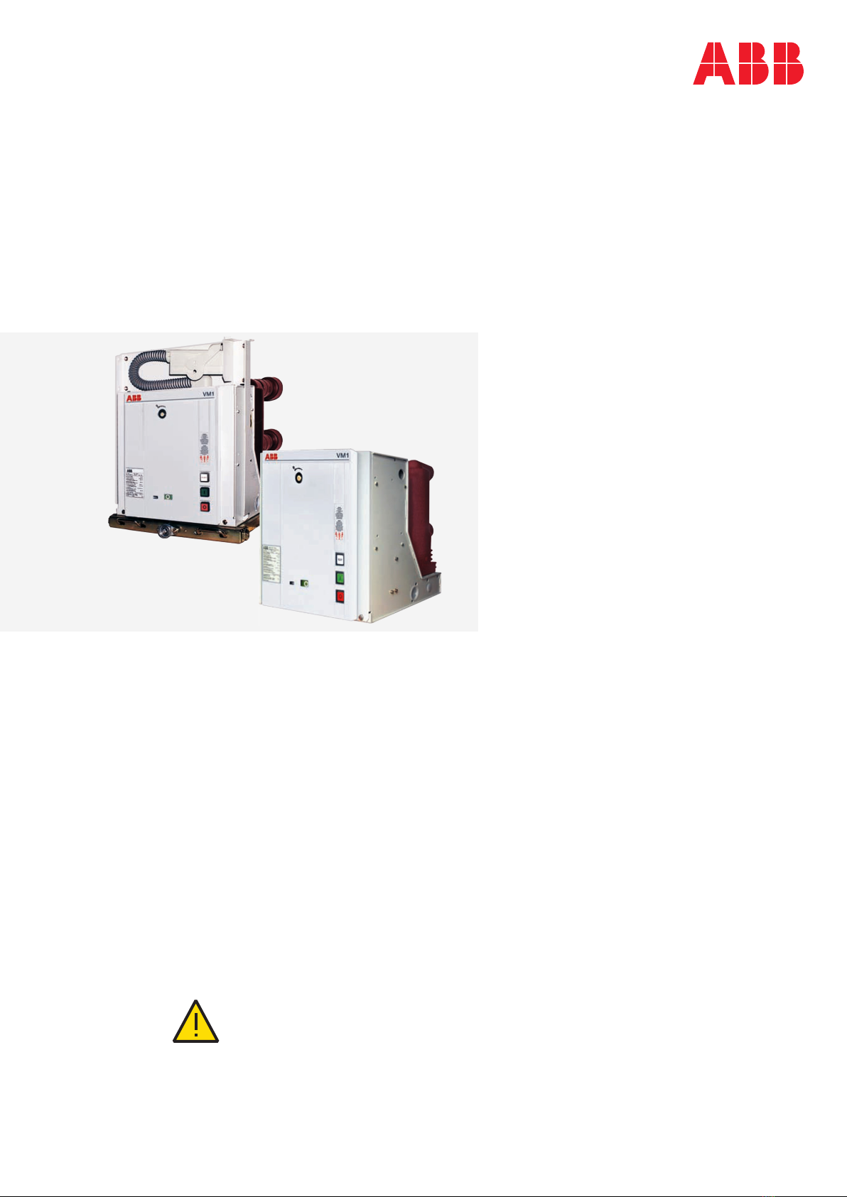
VM1-T - VACUUM CIRCUIT BREAKER8
—
3. Function
3.3 Quenching principle of the
vacuum interrupter
Due to the extremely low static interrupter chamber
pressure of 10-4 to 10-8 hPa, only a relatively small
contact gap is required to achieve a high dielectric
strength. The vacuum arc is extinguished on one of
the first natural current zeros.
Due to the small contact gap and the high
conductivity of the metal vapour plasma, the arc
drop voltage, and additionally, due to the short
arcing time, the associated arc energy, are
extremely low, which has advantageous effects on
the life of the contacts and thus on that of the
vacuum interrupters.
3.4 Interlocks
3.4.1 Interlocks/protection against
maloperation (for C.B. on withdrawable
parts)
(Figure 9/8)
A series of interlocks are provided to prevent
dangerous situations and any maloperation. The
interlocks of the panel system ZS and/or the
Powerbloc/mounting frame, which are normally
effective, are as follows (concerning the circuit
breaker):
The withdrawable part can only be moved from
the test/disconnected position into the service
position (and back) with the circuit breaker open
and the blocking magnet supplied.
The circuit breaker can only be closed if the
withdrawable part is precisely in the defined test
position or service position (electrical interlock).
The circuit breaker can only be opened manually in
the service or test position when no control
voltage is applied, and it can not be closed.
The panel is equipped with devices which allow
the connection and disconnection of the control
wiring plug 36.1 only in the test/disconnected
position.
Details of any additional interlocks, e.g. in
connection with a blocking magnet on the
earthing switch operating mechanism, can be
found in the order documents for each individual
case.
3.4.2 Interlocks for VM1-T withdrawable parts
3.4.2.1 Interlocks when ABB withdrawable
assemblies are used
(Figures 9/9 and 9/26)
1. The VM1-T can only be closed via input -MC when
a voltage of 24 V to 240 V AC/DC is applied to
input -RL1 (electrical closing lock-out).
2. The VM1-T can only be closed when the
withdrawable assembly is in service or test
position. In the intermediate positions, the
voltage for the closing lock-out is interrupted by
auxiliary switches -BT2 / -BT1.
3. A mechanical interlock 35.5 and 41.2 prevents a
closed breaker that is not in the OFF position
being moved.
3.4.3 Interlocks when non-original withdrawable
assemblies are used
(Figure 9/26)
VM1-T circuit breakers which are not mounted on
ABB withdrawable part must be electrically
interlocked with one or two additional auxiliary
switches. These must interrupt the input voltage to
the electrical closing lock-out (input -RL1).
In a similar manner to auxiliary switches -BT2 and
-BT1 on the ABB withdrawable part, no further
electrical pulse may be received by -RL1 after the
first half revolution of spindle system 35.1, and it
may only be re-applied after the last half revolution.
This ensures that the circuit breaker cannot be
closed when the withdrawable part is in an
intermediate position.
A mechanical interlock as described in 3.4.2.1 part 3.)
is to be implemented to prevent a circuit breaker
which is not in the OFF position being moved. The
slide blocker 41.2 on the VM1-T (optional accessory
for stationary mounted breakers) can be used for
this purpose: the slide blocker is outside base plate
41.4. Figure 9/9 shows pawl 35.5 on the ABB
withdrawable part. With the circuit breaker not in
the OFF position, pawl 35.5 cannot be moved
upwards. This prevents movement of the
withdrawable assembly and therefore movement of
the circuit breaker.
Note:
Additionally fitted interlocks must not exert any
force on the operating mechanism of the circuit
breaker.
If the interlock mechanism projects beyond the base
of the circuit breaker casing, measures must be
taken to prevent the the circuit breaker from
weighing down on the interlock, for instance during
transport.

MEDIUM VOLTAGE PRODUCTS 9
—
4. Despatch and storage
4.1 Condition on delivery
• The factory-assembled switching devices are
checked at the works for completeness of the
equipment installed and simultaneously
subjected to a routine test in accordance with
VDE 0670, part 1000 or IEC publication 60694,
thus verifying their correct structure and
function.
The storage capacitors 26 are discharged by the
connected control electronics, and have a terminal
voltage < 10 V on delivery.
4.2 Packaging
The switching devices are mounted individually on a
wooden pallet and sealed in film and/or packed in
cardboard for delivery.
Packaging for overseas shipment:
Drying agent bags inserted in the film sealed
packaging.
Drying agent bags according to DIN 55 473.
4.3 Transport
Loading of the package units must only be carried
out with a
crane,
fork-lift truck and/or
trolley jack.
Notes:
Avoid impact during handling.
Do not subject to other damaging mechanical
stresses.
Lifting gear must not be attached to the breaker
poles or parts of the operating mechanism. Use
lifting bores 1.2 and lifting lugs, e.g. in figure 9/10
and in the dimensional drawings.
4.4 Delivery
The duties of the consignee on receipt of the
switching devices at site include the following:
Checking the delivery for completeness and
freedom from damage (e.g. moisture and its
adverse effects).
Any short quantities, defects or damage in transit:
- Must be precisely documented on the
consignment note.
- The shipper/carrier is to be notified immediately
in accordance with the liability provisions of the
German general conditions for forwarders
(ADSp/KVO).
Note:
Always document any major damage with
photographs.
4.5 Intermediate storage
Conditions for optimum intermediate storage:
1. Devices with basic packaging or unpacked:
A dry and well ventilated storeroom with
climate in accordance with VDE 0670, Part
1000 / IEC 60694.
Room temperature which does not fall below
-25 °C.
Do not remove or damage the packaging.
Unpackaged devices:
- Are to be loosely covered with protective
sheeting.
- Sufficient air circulation must be maintained.
Check regularly for any condensation.
2. Devices with seaworthy or similar packaging
with internal protective sheeting:
Store the transport units:
- protected from the weather,
- dry,
- safe from damage.
Check the packaging for damage.
If the maximum storage period starting from
the date of packaging has been exceeded:
- The protective function of the packaging is
no longer guaranteed.
- Suitable action must be taken if intermediate
storage is to continue.
3. Storage capacitor 26:
There is no limit on storage when the above
conditions are fulfilled.

Careful and professional installation of the
switchgear is one of the fundamental conditions of
trouble-free circuit breaker operation.
Install the mechanism enclosure in the panel
without distortion, placing a dished washer under
the nut and bolt head at each of the four mounting
points (depending on the order).
Connect the main terminals without any residual
tension or pressure forces, exerted for example by
the conductor bars.
When connecting the conductor bars, the bolts
must be inserted to the depth shown on the
dimensional drawing.
Observe the tested terminal zone where
appropriate.
Use DIN bolts of tensile class 8.8 together with
dished washers to fasten the conductor bars.
Only use the tightening torques shown in the
following table.
Remove any contamination (see also section
7.3.1.).
Recommended
tightening torque (1)
Nm
Lubricant (2)
Thread without (dry) Oil or grease
(1) The rated tightening torques for fasteners without lubrication are
based on a coefficient of friction for the thread of 0.14 (the actual
values are subject to an unavoidable, partly not inconsiderable,
spread).
Rated tightening torques for fasteners with lubrication in accordance
with DIN 43 673.
(2) Thread and head contact surface lubricated.
Any tightening torques which deviate from those in the general
table (e.g. for contact systems or device terminals) are to be taken
into account as stated in the detailed technical documentation. It is
recommended that the threads and head contact surfaces of screws
should be lightly oiled or greased, so as to achieve a precise rated
tightening torque.
VM1-T - VACUUM CIRCUIT BREAKER10
—
5. Installation and mounting of the breaker

MEDIUM VOLTAGE PRODUCTS 11
6.1 Notes on safety at work
Operation is only permissible by specially trained
personnel who are familiar with the characteristics
of the particular switching device.
Observe the relevant specifications as set out in
section 1.2.
Before a VM1-T on the withdrawable part is moved
it must be verified that the circuit breaker is
switched off. This is the case when the mechanical
position indicator 6 shows the position “O” and
when “READY” is shining on the READY lamp 2
while the breaker is supplied with auxiliary
voltage.
Due to safety reasons, the circuit breaker has to be
treated as “switched on” if the switching position
can not be clearly determined. In this case all high
voltage connections to the breaker have to be de-
energized and zero potential on the primary side
of the breaker has to be confirmed prior to
commissioning, operation, maintenance or repair
work.
The discharge energy of the storage capacitor is
greater than 350 mJ. The procedure for discharge
of the storage capacitor as set out in section 7.1 is
to be observed.
6.2 Preparatory activities (before
connecting the primary
voltage)
Check the circuit breaker, withdrawable part,
contact arms, insulating parts etc. for damage,
and restore to their proper condition if necessary.
Remove any dirt collected during transport,
storage or installation (particularly on the
insulating materials) as described in section 7.3.1.
Remove lifting lugs T (Figures 10/2, and 10/5).
Check the primary and secondary connections and
the protective earth conductor connection.
Check the connection of the main earthing bar
with the station earthing conductor (DIN VDE
0141).
Remove all material residues, foreign bodies and
tools from the switchgear.
Properly refit all covers, etc., removed during
assembly and testing processes.
Connect the supply voltage (Figures 9/15b, 10/7
and 10/8) - “READY” will shine. Inputs -RL1:
“Closing lock-out” and -MU: “Undervoltage
release” (if applicable) must be supplied with
power before the circuit breaker can be closed.
For this reason, an internal circuit applies a
voltage of 80 V to the input -RL1 (Figure 9/15b), as
soon as the storage capacitor is charged in as-
delivered condition of devices with no connector
wiring.
“READY” will shine even if the closing operation is
blocked by inputs -RL1 or -MU.
If no voltage is applied to input -RL1, closing is
impossible.
If no voltage is applied to input -MU, closing is
impossible in case of activated -MU and not
activated closing support.
Storage capacitors 26:
Following a (de-energised) storage period of more
than 2 years, reforming on initial start-up leads to
a temporary increase in current consumption at
the AC/DC converter, which is however below 2 A.
Check mechanical and electrical interlocks for
effectiveness, without using force.
Perform test closing and opening of the circuit
breaker by pressing push-buttons 3 and 4 (see
Figure 9/16).
On motor-driven withdrawable parts, check the
direction of rotation of the travel motors as
described in section 7.5.3.
For any further questions on the functions of the
withdrawable circuit breaker part and its testing,
see section 7.5.
Instruct the local operators in the fundamental
details of regular handling of the switchgear.
6.3 Earthing
For the fixed version circuit breaker, carry out
earthing by means of the special screw marked with
the relative symbol.
Clean and degrease the area around the screw to a
diameter of about 30 mm and, on completion of
assembly, cover the joint again with Vaseline grease.
Use a conductor (busbar or braid) with a cross-
section conforming to the Standards in force.
—
6. Commissioning / Operation

VM1-T - VACUUM CIRCUIT BREAKER12
6.4 Movement of the
withdrawable breaker part
(Figures 9/9, 9/16 and 9/20 to
9/22)
Perform switching operations with the front doors
shut.
6.4.1 Manual insertion from the test/
disconnection position to the service
position
Connect control wiring plug 36.1.
Close the front door.
Ensure that the circuit breaker is in the OFF
position.
Fit hand crank 38 on square spigot 35.2 of the
spindle mechanism 35.1.
Note:
In order to avoid damage to the operating
mechanism, use the original hand crank only:
Standard version without slip clutch,
Optional version with slip clutch.
Turn the crank clockwise according the table until
the stop is reached and the withdrawable part 31
is in the service position.
Note:
Do not use force to move the withdrawable breaker
part (Maximum torque 25 Nm!)
Comply with the conditions for movement of the
withdrawable part as set out in section 7.5.4!
Panel type Number of crank turns
Observe the position indicator in the front door.
Remove hand crank 38 by first pressing slightly
against the hand crank and then remove.
Note:
When removing the crank, it is essential to ensure
that the spring-loaded guide 35.6 slides into the
untensioned front position. Spindle 35.1 is thus
locked in place, preventing inadvertent turning of
the spindle. Turning of the spindle opens auxiliary
switches -BT2 / -BT1 and thus prevents the circuit
breaker from being operated.
Note:
The withdrawable part must not be stopped at any
position in the travel range between the service
position and test/disconnected position!
—
6. Commissioning / Operation
6.4.2 Manual withdrawal from the service
position into the test/disconnected
position
Ensure that the circuit breaker is in the OFF
position.
Reverse the procedure described above for
insertion into the service position.
Note:
Withdrawable parts with blocking magnet -RL2 may
not be forcibly moved during power failures. In such
a case they are blocked in the service and test
positions. For deblocking, see section 7.5.4.
6.4.3 Motor-driven movement of the
withdrawable part
Briefly operate the electrical control for insertion
or withdrawal (the withdrawable part then
automatically moves into the opposite position).
Observe the position indicator in the front door.
Note:
When the motor fails, the withdrawable part can be
moved in emergency manual operation. If the drive
motor fails during movement of the withdrawable
part, the withdrawable part must be moved into a
limit position in emergency manual operation.
Emergency manual operation:
Emergency manual operation is carried out with the
hand crank 38 on the spindle mechanism 35.1, in a
similar manner to operation of a withdrawable
breaker part with manual systems:
Turn off the supply voltage (m.c.b.), since the
motor would otherwise be braked electrically.
Turn hand crank 38 in the required direction.
When the withdrawable part moves, the motor
turns. The motor functions in such a case like a
generator, i.e. it can lead to reverse voltages in the
terminals.
The motor protection device must not be changed
from the specified type and rated value, or the
behaviour of the permanent magnet motor could
be irreversibly impaired.

MEDIUM VOLTAGE PRODUCTS 13
6.4.4 Withdrawal from the test/disconnected
position onto the service truck
(Figures 9/21 and 9/22)
Open the door of the circuit breaker compartment.
Pull out control wiring plug 36.1 and place it in the
receptacle provided.
Position service truck 40 with the guide pins 40.2
of the adjustable bench top at the correct height
facing the panel front, and allow catch 40.3 to
engage.
Move sliding handles 35.3 inwards against the
springs to release withdrawable part 31, withdraw
onto the service truck and secure it in the catches
on the truck.
Press the release lever (at the front underneath the
bench top) and release the service truck from the
panel.
6.4.5 Insertion from the service truck into the
test/disconnected position
Carry out the procedure as described above for
withdrawal, changing the order accordingly.
6.5 Operation of the circuit
breaker (Figures 9/16 to 9/19)
Voltage is applied when switching readiness is
indicated (“READY” lamp 2 lights up).
Please also observe the notes in section 3.1.5.
1. Closing:
By remote control, by applying a voltage to input
-MC (see also sections 10.1.1a and 6.2) or locally
by pressing ON pushbutton 3.
2. Opening:
By remote control, by applying a voltage to input
-MO1 (see also sections 10.1.1a and 6.2) or locally
by pressing OFF pushbutton 4.
3. Opening on failure of the supply voltage:
a) Initially, for a period of 180 seconds, opening
by remote control or by pressing pushbutton
4 is still possible.
b) During the subsequent period, emergency
manual opening of the breaker is possible.
Insert emergency OFF lever 28 into the
receptacle 8 on the front plate and turn it
anti-clockwise to open the circuit breaker.
First, spring 29 on lever 28 has to be
tensioned. At the end of the tensioning
motion (approx. 65° to 70°) a tangible
resistance caused by the disengagement of
the actuator armature has to be overcome.
The circuit breaker is then switched off, and
any further turns would have no effect.
4. Closing on failure of the supply voltage:
Closing is not appropriate and not possible.
5. Operating cycle and switching condition
indicators on the switching device:
After every operating cycle (ON-OFF), operating
cycle counter 5 is incremented by one full digit.
On completion of a switching operation, switch
position indicator 6 shows the current switch
position.
6. Anti-pumping system:
The circuit breaker controller ensures that
closing of the circuit breaker is blocked when
an opening command is active.
On closing with a following opening command,
renewed closing while the closing command is
still applied is blocked. A further closing
command has to be issued for the next closing
operation.

VM1-T - VACUUM CIRCUIT BREAKER14
—
7. Maintenance
Maintenance serves to preserve trouble-free
operation and achieve the longest possible working
life of the switchgear. In accordance with DIN 31 051
and IEC 61208, it comprises the following closely
related activities:
Inspection:
Determination of the actual condition
Servicing:
Preservation of a functional condition
Repair:
Measures to restore the functional condition
7.1 General
All vacuum circuit breakers are simple and robust in
design. They can be expected to have a long service
life. The vacuum is not even impaired by frequent
switching of operating and short-circuit currents.
The typical life expectancy of a VM1-T vacuum circuit
breaker is a function of:
Maintenance-free, embedded vacuum interrupters
for up to 2,000 mechanical operating cycles.
Maintenance-free control module with sensor
system and no auxiliary switches.
Auxiliary switch for ON/OFF position signalling
(optional) for up to 2,000 operating cycles.
Withdrawable assembly: With careful operation
and appropriately performed inspection work, up
to 1,000 movements can be performed.
See also IEC 60298.
Concerning detailed information about the
maintenance of the VM1-T circuit breaker please
contact the ABB service.
The service life data fundamentally refer to all
components which are not directly influenced by the
operator.
Deviations can occur for parts operated manually
(movement of the withdrawable part, etc.),
depending on how they are handled.
The servicing intervals and scope are determined by
the environmental influences, the switching
frequency and the number of short-circuit breaking
operations.
Note:
The following must be observed for all maintenance
work:
The relevant specifications in section 1.2.2
Notes on safety at work in section 6.1
Standards and specifications in the country of
installation.
Maintenance work may only be performed by fully
trained personnel, observing all the relevant safety
regulations. It is recommended that ABB after-sales
service personnel should be called in, at least during
the performance of servicing and repair work.
While the work is in progress, and if the work
permits, all supply voltage sources must also be
disconnected and secured to prevent re-connection.
Note:
In order to prevent accidents (particularly injury to
hands!) extreme care should be taken during all
repair work on the operating mechanism, especially
with front plate 1.1 removed.
The energy of the storage capacitor can be released
uncontrollably during incorrect handling!
Procedure for capacitor discharge:
1. Close the circuit breaker.
2. Turn off the supply voltage (m.c.b.).
3. Switch the circuit breaker in the following cycle
by pressing pushbuttons 3 and 4: OFF/ON/OFF.
On completion of this switching cycle the
“READY” lamp goes out, i.e. the circuitbreaker is
no longer ready for operation.
4. After approx. 12 minutes, the storage capacitors
have discharged to less than 15 V:
In addition to this instruction manual, it may be
necessary in individual cases to observe further
details in the technical documentation for the
switchgear (e.g. on special operating conditions
if stipulated).
7.2 Inspection and functional
testing
7.2.1 Circuit breaker in general
Under normal operating conditions, inspection
within the stated number of operating cycles is
not necessary.
Inspection may be necessary under exceptional
operating conditions (including adverse climatic
conditions) and/or particular environmental
stresses (e.g. serious contamination and
aggressive air).
The inspection primarily comprises visual
examination for contamination, corrosion,
moisture and discharge phenomena on the high
voltage side.
If an irregular condition is found, appropriate
maintenance work is to be initiated.

MEDIUM VOLTAGE PRODUCTS 15
No external discharge may occur on the surfaces
of equipment at operating voltage. This can, for
example, be detected by characteristic noises, a
clearly perceptible smell of ozone, or visible
glowing in the dark.
If irregular conditions are detected, then
corresponding repair measures should be
initiated.
7.2.2 Magnetic actuator operating mechanism
(Figures 9/11 and 9/19)
A first functional test of the operating mechanism is
to be performed:
after the stated number of operating cycles, or
during maintenance work as described in section
7.2.1.
Before the functional test, open the circuit breaker
and
move it into the test position (withdrawable
breaker) or
isolate and secure the working area in accordance
with the Safety Regulations to DIN VDE / IEC (with
stationary mounted breakers).
Observe the procedure for capacitor discharge as
set down in section 7.1.
Perform visual examination of the condition
(removing front plate 1.1), e.g.:
- the lubrication at the rotary bearings,
- the operating cycle counter,
- the sensor mounting,
- the position indicator.
Scope of functional testing:
Connect the supply voltage.
Perform several switching operations under no
load. This is predominantly applicable to circuit
breakers which are rarely operated under normal
circumstances.
Perform one rapid OFF/ON/OFF operation with
the circuit breaker to check the storage capacitors
by pressing buttons 3 and 4 rapidly in sequence.
The LEDs on the inductive proximity switches 15
and 16 are activated when the circuit breaker has
reached its OFF and ON limit positions
respectively.
7.2.3 Withdrawable part
The inspection should always include a visual
examination of the withdrawable part assembly.
Special attention is to be paid to those parts
which may possibly be damaged by improper
handling.
Perform a visual check on the condition of the
isolating contact system. It is recommended that
the contact system be turned alternately so that
its inner contact points can be cleaned.
If there are signs of impermissible overheating
(discoloured surface), the contact points are to be
cleaned (see the section on repairs).
The interlock conditions and the ease of
movement of the withdrawable assembly are to be
checked as described under “Repair”.
When checking the interlock conditions, it is
essential to ensure that no force is used.
Maximum torque 25 Nm!
7.3 Servicing
7.3.1 Circuit breaker in general
If the necessity of cleaning is established during
inspections as described in 7.2.1, the following
procedure is to be adopted:
Prior to cleaning, isolate and secure the working
area if necessary in accordance with the safety
regulations of DIN VDE and IEC.
Observe the procedure for capacitor discharge as
set down in section 7.1.
Cleaning of surfaces in general:
- Remove weakly adhering dry dust deposits with
a soft dry cloth.
- Remove more strongly adhering dirt with a
slightly alkaline household cleanser, or with
Rivolta BWR 210.
Cleaning of insulating material surfaces and
conductive parts:
- Minor contamination: with Rivolta BWR 210.
- Strongly adhering contamination: with cold
cleanser 716.
After cleaning, wipe down with clean water and dry
carefully.
Observe the manufacturer’s instructions and the
special ABB instruction manuals BA 1002/E or BA
1006/E on safety at work.
Note:
Use only halogen-free cleaning agents. Never use
1.1.1-trichloroethane, trichloroethylene or carbon
tetrachloride!
7.3.2 Magnetic actuator operating mechanism
The magnetic actuator mechanism is maintenance-
free up to the number of operating cycles stated in
section 7.1.

VM1-T - VACUUM CIRCUIT BREAKER16
7.3.3 Breaker pole
The breaker pole with the vacuum interrupter is
maintenancefree up to the permissible number of
operating cycles as sent down in section 10.1.3.
The working life of the vacuum interrupter is defined
by the sum current limit corresponding to the
equipment data in individual cases in accordance
with section 10.1.3:
When the sum current limit is reached, the
complete breaker poles are to be replaced.
Note:
Dismantling and replacement of the breaker poles
should only be performed by the ABB after-sales
service or adequately trained specialist staff, in
particular with regard to the necessity for precise
setting.
The following equipment, for example, can be used
to check the vacuum (without dismantling the
circuit breaker):
VIDAR vacuum tester, from
Programma Electric GmbH
Bad Homburg v.d.H., Germany
The following test values have to be set for checking
of the internal interrupter chamber pressure with
the VIDAR vacuum tester:
Rated voltage of the circuit breaker DC test voltage
Testing is to be performed at the rated contact
distance in the OFF condition.
Procedure for vacuum interrupter testing for
stationary mounted switching devices:
Isolate and secure the working area in accordance
with the Safety Regulations to DIN VDE / IEC.
Open the VM1-T circuit breaker.
Earth all poles of the VM1-T circuit breaker on one
side.
Connect the earthed test lead of the VIDAR
vacuum tester conductively to the station earth.
Connect the high voltage test lead of the VIDAR
vacuum tester with phase L1 of the unearthed pole
side and test the vacuum interrupter chamber with
the circuit breaker contact gap open. Repeat for
phases L2 and L3.
Note:
Connected cables may lead to a “defective”
indication on the vacuum tester as a result of their
cable capacitance. In such cases, the cables are to
be removed.
7.4 Repair
7.4.1 Repair of surface damage
Circuit breaker part in general
Sheet steel parts, painted:
- Remove rust, e.g. with a wire brush.
- Grind off paint coat and degrease.
- Apply anti-rust primer and top coat.
- Use a top coat in the standard colour RAL 7035
or the relevant special colour.
Sheet steel parts with aluminium-zinc surfaces
and chromated functional parts:
- Remove white rust, with a wire brush or cleaning
pad (e.g. Scotch-Brite, white).
- Remove loosely adhering particles with a dry
cloth.
- Apply zinc spray or zinc dust primer.
Functional parts, phosphated:
- Remove rust, with a wire brush or cleaning pad
(e.g. Scotch-Brite, white).
- Clean with a dry cloth.
- Grease with Isoflex Topas NB 52 lubricant.
Withdrawable circuit breaker part in general:
Where required, regrease or thoroughly clean slide
plates and bearings in the panel and regrease
them with Isoflex NB 52 lubricant.
Remove the contact system for thoroughly
cleaning as described below (Figures 9/23 and
9/24:
- Slide the two inner annular tension springs 34.2
facing the breaker pole to a position beside the
other two outer annual tension springs, thus
releasing contact system 34.1, and remove the
contact system from contact arm 34.
- The contact pin of the contact system and the
slot on the contact arm are to be cleaned and
greased.
- Fit the contact system back to front on the thin
end of arbor 39, and slide it forwards onto the
thicker part of the shank.
- Fit arbor 39 onto the relevant contact arm 34,
slide the contact system 34.1 over onto the
contact arm, and withdraw the arbor.
- Check all contact fingers and annular tension
springs for perfect fit.
Note:
The set installation position of contact arms 34
must not be changed by the improper use of force.
7.4.2 Replacement of components
Only remove and reassemble circuit breaker parts
and accessories when the breaker has been
switched off and the working area is to be isolated
and secured against reclosing.
—
7. Maintenance

MEDIUM VOLTAGE PRODUCTS 17
All supply voltage sources must be disconnected
and secured to prevent reconnection during the
removal and installation work.
The storage capacitor is to be discharged in
accordance with the instructions in section 7.1.
1. Circuit breaker control module:
- Replacement of the circuit breaker control
module may only be performed by ABB after-
sales service personnel or by specially trained
specialists. This is because the internal
sequence times are set by jumpers on each
individual control unit.
2. Withdrawable assembly:
(Figures 9/8, 9/9, 9/26 and 9/27)
Disconnect plug connector 37.
For motorized withdrawable assemblies, remove
the two socket head bolts which are accessible
from below the assembly.
Unbolt the circuit breaker from the withdrawable
assembly (4 x M12 bolts).
Mount the circuit breaker on a new withdrawable
assembly in the reverse order.
Check the settings of the slide blocker 41.2:
- The circuit breaker is in the ON position.
- The distance between pawl 35.5 on the with-
drawable assembly and slide blocker 41.2 must
be 0.1 + 0.4 mm. If a correction is necessary, the
screws 41.3 are to be released and the slide
blocker 41.2 is to be adjusted by a feeler gauge.
Thereafter the screws must be fixed again.
7.5 Test on withdrawable parts
with VM1-T type circuit
breakers
The following conditions are to be checked to test
the function of the withdrawable part.
7.5.1 Motor-driven withdrawable parts
(non-standard)
Inspection of motor-driven withdrawable parts
should be performed as for manually operated
withdrawable parts in accordance with Section
7.5.2:
Turn off the supply voltage (m.c.b.), since the
motor could otherwise be braked electrically.
Turn hand crank 38 in the required direction (see
Figure 9/25).
Note:
When the withdrawable part moves, the motor
turns. The motor functions in such a case like a
generator, i.e. it can lead to reverse voltages in the
terminals.
7.5.2 Checking the auxiliary switch settings
on withdrawable parts
(Figures 9/14 and 9/25)
Compliance with the interlock conditions in the
test/disconnected and service position areas is
ensured by position signalling switches -BT2 and
located in the withdrawable assembly and factory-
set.
In test operations, the withdrawable part must be
moved by hand with the crank fitted with the motor
power switched off.
1. Settings in the area of the test/disconnected
position:
Move the withdrawable part out of the test/
disconnected position towards the service
position with a few turns of the crank.
Slowly move the withdrawable part back to the
stop. Auxiliary switch -BT2 must then switch
over just before the stop is reached.
Slowly insert the withdrawable part from the
test/ disconnected position towards the
service position until auxiliary switch -BT2 just
operates (approx. 30° rotation of the crank). It
is no longer possible to switch the circuit
breaker on in this position.
When the hand crank is turned further, the
position of the circuit breaker is polled by pawl
35.5 after a total angle of turn of approx. 90°. If
the circuit breaker is closed, the withdrawable
part cannot be moved any further.
For this test, the function of the blocking
magnet -RL2 (if fitted) must be disabled
manually.
2. Settings in the area of the service position:
Move the withdrawable part out of the limit
position towards the test/disconnected
position with a few turns of the crank.
Slowly move the withdrawable part forwards
again to the stop. Auxiliary switch -BT1 must
then switch over just before the stop is
reached.
Slowly move the withdrawable part out of the
service position towards the test/
disconnected position until auxiliary switch
-BT1 just responds (approx. 30° rotation of the
crank). When the hand crank is turned further,
the position of the circuit breaker is polled by
pawl 35.5 after a total angle of turn of approx.
90°. If the circuit breaker is closed, the
withdrawable part cannot be moved any
further.

VM1-T - VACUUM CIRCUIT BREAKER18
7.5.3 Checking the direction of rotation of the
travel motors on motor-driven
withdrawable parts
Move the withdrawable part by hand into a central
position between the test/disconnected position
and the service position.
Remove the hand crank.
Switch the supply voltage for the travel motor on.
Use the local electrical controls to check that the
withdrawable part moves in the correct direction.
Caution:
Do not allow the withdrawable part to run up
against a block when the travel direction is
incorrect! Switch the motor power off immediately
(the travel process functions electrically by a seal-in
system with limit position switch-off).
There may be a danger of injury when the door is
open!
7.5.4 Checking of interlock conditions
(Figures 9/16 and 9/20)
1. The withdrawable part must only be movable
from the test/ disconnected position into the
service position when the circuit breaker is open.
Check this conditions as follows:
With the circuit breaker closed, insertion of the
withdrawable part towards the service
position must be blocked after only half a turn
of the crank in the clockwise direction, and the
travel motor on motor-operated withdrawable
parts must not be capable of being switched
on.
Do not use force
(maximum torque 25 Nm)!
2. The withdrawable part must only be movable
from the service position into the test/
disconnected position with the circuit breaker
open.
Check this condition as follows:
With the circuit breaker closed, withdrawal
movement of the withdrawable part must be
blocked after only half a turn of the crank in the
anti-clockwise direction, and the travel motor
on motor-operated withdrawable parts must
not be capable of being switched on.
3. Closing of the circuit breaker must only be
possible when the withdrawable part is in the
defined test/disconnected position or service
position.
The control wiring plug 36.1 must previously
have been inserted.
Check this condition as follows:
It must not be possible to close the circuit
breaker with the withdrawable part in any
position between the test/ disconnected
position and the service position.
Readiness for switching is established
electrically when the service position is
reached by auxiliary switch -BT1 in the
withdrawable assembly switching over.
For motion into the test/disconnected
position, the same enabling conditions apply
analogously, in this case by means of auxiliary
switch -BT2 in the withdrawable assembly.
4. It must only be possible to open the circuit
breaker manually in the service position and in
the test/disconnected position on failure of the
supply voltage:
a) Initially by pressing OFF pushbutton 4, until
180 seconds have expired.
b) In subsequent periods, emergency manual
opening with operating lever 28 is possible.
5. Withdrawable parts with order-related blocking
magnet -RL2 may not be moved in case of
control power failure, or when there is no control
power. Do not forcibly move blocked
withdrawable parts! The blocking magnet -RL2 is
only present on manually operated withdrawable
parts (Figure 9/25).
Releasing the blocking magnet -RL2:
Remove front plate 1.1,
disengage blocking magnet -RL2 by pulling the
magnet armature,
while doing so, turn crank 38 about one half
turn (either direction of rotation is
permissible).
The blocking magnet is only active in the test
position and service position. In intermediate
positions it has no effect.
7.6 Spare parts, auxiliary
materials, lubricants
7.6.1 Spare parts
When parts are required, the serial number of the
relevant withdrawable breaker part or circuit
breaker should always be quoted. Setting
instructions are to be requested separately.
Withdrawable assembly of VM1-T:
Manually movable withdrawable assembly:
- See drawing GCE 7003570, sheets 1 and 2, for
notes for setting of auxiliary switches -BT2 /
-BT1 and slide blocker.
Motor-driven withdrawable parts:
- For notes on settings see drawing GCE 7003571.
Blocking magnet -RL2:
- For notes on settings see drawing GCE 7003820,
sheet 1 (table 2).
—
7. Maintenance

MEDIUM VOLTAGE PRODUCTS 19
Designation Part no. (order code)
Lubricant:
Halogen-free cleansers:
components of insulating materials and in case of serious grime!)
Paint:
- Spray tin
7.6.2 Auxiliary materials and lubricants
Table: VM1-T withdrawable part
Designation Item
no.
Rated supply
voltage
Part no.
(order code)
Auxiliary switch for manually operated mechanism
- Silver-plated contacts
- Gold-plated contacts
Auxiliary switches for motor-operated driving mechanism
- Silver-plated contacts
- Gold-plated contacts
Blocking magnet
Motor with gearbox -MT
Designation Item
no.
Part no.
(order code)
Auxiliary switch for ON/OFF position signalization
- Silver-plated contacts
- Gold-plated contacts
Designation Rated supply
voltage
Part no.
(order code)

VM1-T - VACUUM CIRCUIT BREAKER20
One of the physical properties of vacuum insulation
is the possibility of X-ray emissions when the
contact gap is open.
The specified test performed by the Physikalisch-
Technische Bundesanstalt (PTB) in Braunschweig
demonstrates that the local dosage output of 1
surface is not exceeded when the rated voltage is
applied.
The results are as follows:
Testing of the switching device or the vacuum
interrupter to VDE 0671 part 100 or IEC 62271-100
at the relevant rated power frequency withstand
voltage may only be performed by trained
personnel observing the stipulations of the EU
basic standard (Stipulation 96/29/Euratom of the
senate from 13 May 1996 (ABI.L 159 from 29 June
1996)).
Application of the rated voltage specified for the
switching device by VDE 0671 part 100 or IEC
62271-100 is completely safe.
Higher voltages than the rated voltage or DC test
voltage specified in VDE or IEC standards must
not be applied!
The containment of the above mentioned local
dosage output with the vacuum interrupter in the
open position is dependent on maintenance of the
specified distance between the contacts (which is
automatically ensured with correct mechanism
function and force transmission).
Safety clearances must be maintained.
—
8. Application of the X-ray regulations
Table of contents
Other ABB Circuit Breaker manuals

ABB
ABB RELION 650 SERIES Instructions for use

ABB
ABB FH200A User manual

ABB
ABB AKD6-800A User manual

ABB
ABB GE Power Break II GEH6271 User manual

ABB
ABB Tmax T8 L5757 Guide

ABB
ABB SACE Tmax XT5 User manual

ABB
ABB Emax User manual

ABB
ABB Ekip UP Series User manual

ABB
ABB SMISSLINE CLASSIC FS451 Service manual

ABB
ABB ReliaMod RMS212522LRLR User manual