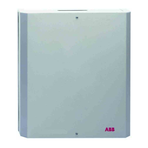
ABB SAS-W1.1E User guide

—
2CSM6007 30D0901_REV G | 01.02.202 1
Busch-/ABB-secure@home
System Manual
Types of Central Unit
With GSM
SAS-W1.1E SAS-W1.11E
SAS-W1.1F SAS-W1.11F
SAS-W3.1E
Basic
SAS-W2.1E SAS-W2.11E
SAS-W2.1F SAS-W2.11F

BUSCH -/ABB-SECUR E@HOME
2CSM600727 D090 1 2/74
Contents
1Introduction ................................................................................................................................5
1.1 Where to find the information ..................................................................................................5
1.2 Conformity ....................................................................................................................................5
1.3 Disclaimer......................................................................................................................................5
1.4 Trademarks and copyrights ..................................................................................................... 6
Use the system .................................................................................................................................7
2Command interface ....................................................................................................................7
2.1 Display ............................................................................................................................................7
2.1.1 Meaning of the icons................................................................................................ 8
2.1.2 Authentication ........................................................................................................... 9
2.1.3 Main user menu ......................................................................................................... 9
2.1.4 Status of the individual zones...............................................................................10
2.2 LEDs ..............................................................................................................................................10
2.3 Command interface................................................................................................................... 11
2.3.1 Using the keyboard.................................................................................................. 11
2.4 Authentication............................................................................................................................12
2.4.1 User ID ........................................................................................................................12
2.4.2 Password....................................................................................................................12
2.5 Authorisation level.....................................................................................................................12
3Arming and disarming the system..........................................................................................14
3.1 Arming or disarming using the keypad ................................................................................14
3.1.1 Rapid arming or disarming....................................................................................14
3.1.2 Global arming............................................................................................................16
3.1.3 Global disarming...................................................................................................... 17
3.1.4 Partial arming............................................................................................................ 17
3.1.5 Partial disarming...................................................................................................... 17
3.2 Arming or disarming using the remote control .................................................................. 17
3.3 Arming using Forced Block......................................................................................................18
3.4 Reset .............................................................................................................................................19
4Panic and burglary ................................................................................................................... 20
4.1 Activating the panic alarm...................................................................................................... 20
4.1.1 Activation using the keypad ................................................................................. 20
4.1.2 Activation using the remote control................................................................... 20
4.2 Activate the burglar alarm ...................................................................................................... 20
4.2.1 Activation using the remote control................................................................... 20
5Alarms and event memories ....................................................................................................21
5.1 Alarm priority..............................................................................................................................21
5.2 How to block an alarm..............................................................................................................21
5.3 Events history.............................................................................................................................22
5.3.1 View events................................................................................................................22
5.3.2 SMS events ................................................................................................................22
5.3.3 Interpreting a stored event....................................................................................23
6Remote commands ...................................................................................................................25
6.1 SMS Commands ........................................................................................................................ 25
7System status ...........................................................................................................................26
8Central unit settings ................................................................................................................27
8.1 Adjust display .............................................................................................................................27
8.2 Audio Settings........................................................................................................................... 28

BUSCH-/ABB -SECUR E@HOME
2CSM600727 D090 1 3/74
8.2.1 Beep volume............................................................................................................. 28
8.2.2 Sound Feedback ...................................................................................................... 28
8.2.3 Alarms........................................................................................................................ 29
8.3 Setting date and time.............................................................................................................. 30
8.4 Change PIN..................................................................................................................................31
8.5 Operating method and change language ........................................................................... 32
8.6 Customize quick entry............................................................................................................. 33
Install and configure the system ................................................................................................. 34
9Main characteristics ................................................................................................................ 34
9.1 Main functions of the central unit ........................................................................................ 34
9.2 System capacity ........................................................................................................................ 34
10 Designing a system ..................................................................................................................35
10.1 Information on radio waves ................................................................................................... 35
10.2 Use the zones ............................................................................................................................ 36
10.2.1 Zone types ................................................................................................................ 36
10.2.2 Subdivision into zones........................................................................................... 36
11 Installing the central unit.........................................................................................................37
11.1 Workspaces .................................................................................................................................37
11.2 Commissioning ..........................................................................................................................37
11.2.1 Reading operational sequences ...........................................................................37
11.2.2 First start-up............................................................................................................ 38
11.3 Status of the system................................................................................................................ 42
11.3.1 Arm / disarm the system ...................................................................................... 43
11.3.2 Display alarm zones................................................................................................44
11.4 Authentication........................................................................................................................... 45
11.5 General and alarm reports...................................................................................................... 46
12 Programming ........................................................................................................................... 48
12.1 System creation ........................................................................................................................48
12.2 Programming zones and sensors ......................................................................................... 48
12.2.1 To programme a new zone:...................................................................................48
12.2.2 To modify or delete a zone: .................................................................................. 49
12.2.3 To programme a sensor: ....................................................................................... 49
12.3 Programming system devices ................................................................................................51
12.3.1 Remote Control Programming..............................................................................51
12.4 Programming external sirens................................................................................................. 55
12.4.1 Possible parameters............................................................................................... 55
12.4.2 Zones Filters............................................................................................................. 55
12.4.3 Alarms........................................................................................................................ 56
12.4.4 Events ........................................................................................................................ 56
12.5 Repeater programming........................................................................................................... 57
12.5.1 Possible parameters............................................................................................... 57
12.6 Telephone contact programming ......................................................................................... 58
12.6.1 Customised message............................................................................................. 60
12.6.2 Phone message sending sequence..................................................................... 60
12.6.3 Receiving telephone calls from the central unit................................................61
12.7 Home automation free@home...............................................................................................61
12.7.1 Version........................................................................................................................61
12.7.2 Key ...............................................................................................................................61
12.7.3 GTW Reset .................................................................................................................61
12.8 System test ................................................................................................................................ 62
12.9 User management .................................................................................................................... 64
BUSCH -/ABB-SECUR E@HOME
2CSM600727 D090 1 4/ 74
12.9.1 Change a user .......................................................................................................... 65
12.9.2 Deleting a user......................................................................................................... 65
13 Maintenance ............................................................................................................................. 66
13.1 Power management ................................................................................................................. 66
13.1.1 Battery ....................................................................................................................... 66
13.1.2 Electrical power network ...................................................................................... 66
13.2 Placing system in maintenance mode ................................................................................. 66
13.2.1 Replacing the central unit battery....................................................................... 66
13.2.2 SIM Replacement..................................................................................................... 67
13.2.3 Replacing the detector battery............................................................................ 67
13.2.4 Replacing the remote control battery ................................................................ 67
13.2.5 Replacing the siren battery................................................................................... 67
13.2.6 Central unit reset .................................................................................................... 67
13.2.7 Deleting the events log.......................................................................................... 68
13.2.8 Connection ............................................................................................................... 68
13.2.9 Adding devices ........................................................................................................ 68
13.2.10 Deleting devices ...................................................................................................... 68
13.2.11 Replacing devices.................................................................................................... 68
13.2.12 Central unit firmware update............................................................................... 69
14 Problem solving ........................................................................................................................ 71
15 Central unit technical specifications......................................................................................73
16 cyber security disclaimer.........................................................................................................74
16.1 Network Manager ......................................................................................................................74

BUSCH -/ABB-SECUR E@HOME
2CSM600727 D090 1 5/ 74
1INTRODUCTION
Thank you for purchasing the BUSCH-/ABB-secure@home central unit. This manual contains
all of the information that the user needs for day-to-day use of the central unit and the
intrusion alarm system, including configuration and maintenance procedures.
1.1 Where to find the information
This manual contains all of the information to use, configure and maintain the central unit.
It also provides suggestions for planning a security system, includes a list of the technical
specifications of the central unit and sets out the procedures for isolating the system and
resolving any faults. The configuration section is exclusively intended for use by the
technician who installs the system.
1.2 Conformity
The central unit has been designed and built according to quality and safety standards
provided for in the regulations and laws in force. Conformity with qualitative requirements is
confirmed by the inclusion of the CE mark in accordance with regulation 1999/05/EC.
Warning! Installation must only be performed by a qualified electrician.
When installing the system, current national electrical regulations regarding the installation
site must be complied with. It should be noted that the conformity referred to above and the
performance of the product may be compromised by:
-incorrect electrical power supply;
-incorrect installation or incorrect, improper or otherwise inconsistent use of the
instructions provided in the installation and use manual or in the instructions
provided with the devices;
-replacement of original parts or accessories with other types that have not been
approved by the manufacturer, or performed by unauthorised personnel.
In the event of opting for non-conforming configurations, the product labels confirming
conformity must be modified or removed.
1.3 Disclaimer
All the information in this document has been collected and checked with care. However, ABB
and BUSCH-JAEGER cannot be held liable for any printing errors or technical inaccuracies.
ABB and BUSCH-JAEGER reserve the right to improve or change the products described in
this manual at any time and without prior notice. This manual may also contain references or
information about products or services that are not yet on the market. The inclusion of such
references or information does not in any way imply that ABB and BUSCH-JAEGER intend to
market such products or services.

BUSCH -/ABB-SECUR E@HOME
2CSM600727 D090 1 6/74
1.4 Trademarks and copyrights
All trademarks mentioned in the document belong to their respective owners.
© Copyright ABB S.p.A. 2018 - All rights reserved.
© Copyright BUSCH-JAEGER GmbH. 2018 - All rights reserved.
Code
Brand
VdS approval number
SAS-W1.1E
SAS-W2.1E
SAS-W1.1F
SAS-W2.1F
SAS-W1.11E
H121004
SAS-W1.11F
SAS-W2.11E
SAS-W2.11F
WARNING!
The use of the secure@home system in accordance with the VdS guidelines
requires:
-installation of the keylock to arm/disarm the system from outside the home.
The instructions for installation, configuration and use are described in
manual 2CSM600756D0901;
-do not use remote controls, APPs and GSM to arm / disarm the system
remotely.

BUSCH -/ABB-SECUR E@HOME
2CSM600727 D090 1 7/74
USE THE SYSTEM
This section contains all of the information that the user needs for day-to-day use of the
central unit and the intrusion alarm system, including some configuration procedures.
2COMMAND INTERFACE
2.1 Display
The liquid crystal display screen shows all of the information relevant to the configuration of
the central unit and operation of the system. It may contain up to 8 lines of text with up to 20
characters each, or a series of icons, or a combination of text and icons.
The display is normally off, and lights up when a key is pressed.
When idle, the screen displays the following information:
-Status of the system (armed/disarmed/partial armed (Note1))
-2 icons to indicate, from left to right, the status of the central unit power supply and
the GSM connection.
Pressing the key once will bring up detailed information on the status of the individual
zones, while pressing it a second time:
ocentral unit FW release number
ophysical address (8 digits) of the central unit
odate - time
oconnection to ABB-free@home
ogateway free@home fW release number
otouch keyboard Fw level
obattery level
Note 1:
Armed
All zones are armed using the same method
Disarmed
All zones are disarmed
Partially armed
Not all zones are armed or they are armed in a non-uniform manner
System Disarmed

BUSCH -/ABB-SECUR E@HOME
2CSM600727 D090 1 8/74
2.1.1 Meaning of the icons
Status of
Icon
Meaning
Telephone
The connection to the GSM telephone network is working. The
signal strength is displayed using the bars (1 to 3).
GSM telephone network not identified, SIM Card not installed,
not identified, expired or not active.
(flashing)
SIM Card with PIN not removed
GSM modem in energy saving mode
GSM diagnostics in progress.
GSM supervision in progress
Intrusion alarm system
System disarmed.
System armed in "Notification" mode.
Alarm armed in "Home mode”.
Alarm armed in "Away mode”.
Exit delay activated on at least one sensor
24h active zone
Central unit power supply
Indicates the presence of 230V and battery power supply
Battery powered only.
The amount of black infill on the icon indicates the battery
charge. (fully charged in the example).
(flashing) Battery missing

BUSCH -/ABB-SECUR E@HOME
2CSM600727 D090 1 9/74
2.1.2 Authentication
To perform the authentication process when the window is idle:
1. Press the ok key on the key pad. A window will appear showing the level 2 users set up
for the system
2. Select the user from the list and enter the PIN. The numbers entered will be hidden
3. Press the ✓ key to confirm. If the PIN entered is not 5 digits long, the ✓ key will not be
accepted. If the user enters the wrong PIN, a tampering alarm is generated on the
tenth attempt.
4. If the authentication process is successful, the main user menu appears.
2.1.3 Main user menu
The screen is laid out as shown below. When the user accesses this screen, the central unit
automatically switches to the "Arm/disarm" icon
The key allows you to leave the screen and return to the idle screen. The arrows allow
you to navigate to select the desired icon and, therefore, function.
Icon
Meaning
Arm/Disarm. Allows you to access the Arming and Disarming menu for the entire security
system or for individual zones.
Status and list of events. Provides access to the menu showing the events stored by the
central unit and the system status.
Panic. Allows a panic alarm to be activated.
Options. Provides access to the menu to adjust the display, audio, date and time, and modify
your PIN
Installer Access. Provides access to the video of the services enabled for a level 3 user.
System test. Provides access to the system test menu.
Exit. Exit the main menu and return the central unit to idle mode.
Select user
User 1
User 2
User 3
Arm/Disarm

BUSCH -/ABB-SECUR E@HOME
2CSM600727 D090 1 10/74
2.1.4 Status of the individual zones
The status of the zones can be accessed by pressing the key on the idle screen: each zone
can assume the statuses - and therefore the icons - described in the "Intrusion alarm system"
section of the
Meaning of the icons
table - par. 2.1.1.
2.2 LEDs
4 LEDs are located beside the display, on the right.
Indicates that the central unit battery is faulty.
Indicates that mandatory notifications have been stored and not yet viewed. Visible when the
system is deactivated.
Signals an alarm (intrusion, tampering).
Does not signal burglar alarms. Only visible to authenticated users.
Signals system jamming.
In the event of a fault or an alarm, the relevant LED will come on and stay on, unless the
network power supply is not working and only battery power supply is available. If this is the
case, the LEDs will flash slowly (2 seconds on, 6 seconds off) to save power. The notification
LED will switch off automatically when all of the pending faults have been viewed by scrolling
through the various screens using the ‘ > ’ key and returning to the main screen.
In the event of alarms (tampering or intrusion), the LED will only switch off following the
restoration operation.

BUSCH -/ABB-SECUR E@HOME
2CSM600727 D090 1 11/74
2.3 Command interface
2.3.1 Using the keyboard
The central unit is configured with the aid of the keyboard that allows you to navigate
through the voices of the menu, enter digits and letters.
The keyboard (*) consists of 17 keys:
They allow you to navigate between menu items and icons.
Confirm the value entered or selected.
Pressed in any displayed menu, saves the data and moves to the upper menu level.
Alphanumeric keys that allow you to enter numbers or letters.
Exit from the current work session without saving.
Removes a setting or character depending on the context.
standard keypad (**) has 20 keys
Allow you to move between menu options and icons
✓
It confirms the entered or selected value. When pressed anywhere in
the displayed menu, saves the data and moves to the upper menu
level
Alphanumeric keys that allow you to enter numbers or letters
Exit from the current work session without saving.
Removes a setting or character depending on the context.
Allow you to quickly arm and disarm the system.
(*) for all models except SAS-W3.1E
(**) only for model SAS-W3.1E

BUSCH -/ABB-SECUR E@HOME
2CSM600727 D090 1 12/74
2.4 Authentication
In order to access the menus and operate the central unit, authentication is required via an ID
and password, both of which are numerical. The ID and password are stored as codes. Each
user is also assigned specific privileges that determine what they can do. There are no pre-
set factory users. The duration of the work session is 3 minutes for level 2 users and 1 hour
for level 3 users.
2.4.1 User ID
The user ID is a 1 digit numerical code, between 0 and 9, assigned in order by the system
ID 0 is reserved for a level 3 user (installer), ID 1 is for a level 2 user (user) or a level 4 user
(Maintenance personnel).
At least one level 3 user and one level 2 user must be set for each system.
2.4.2 Password
The password (PIN) consists of 5 digits and is chosen freely by the user. The PIN can only be
modified by its owner, using a specific procedure.
2.5 Authorisation level
The authorisation level determines what individual users can and cannot do after
authentication. There are three levels of authorisation:
-Level 2 classifies the users who use the intrusion alarm system on a daily basis.
-Level 3, Installer: can set up or modify the configuration of the system. There can only
be one installer per system. To use the system, a level 3 user must be authorised in
advance by a level 2 user.
-Level 4*. Refers to users who can update or change the central unit firmware. Because
this operation is critical to the proper functioning of the system, it is required to
enable users who have already gone through the authentication process using their
log-in details to be authenticated again on a specific basis.
The star (*) identifies the maintainer, pay attention before deleting this user!
Level 3 Installer users and level 2 Superusers correspond to the authorisation levels of the
same names provided for in regulation EN 50131-1.

BUSCH -/ABB-SECUR E@HOME
2CSM600727 D090 1 13/74
The table below outlines the permissions granted to each authorisation level.
Function
Access level
2
3
4
User
Installer
Maintenance
person
Global arming
■
■
Only permitted arming
■
Total disarming
■
■
Only permitted disarming
■
I&HAS restoration
■
■
Check I&HAS functions
■
■
Event register interrogation
■
■
Inhibition / isolation / override (based on
level)
■
■
Addition / changes to individual
authorisation codes (changes can only be
made to your own code)
■
■
Addition / removal of users and level 2
codes
■
Addition / changes to specific site data
■
Changes / replacement of firmware
■

BUSCH -/ABB-SECUR E@HOME
2CSM600727 D090 1 14/74
3ARMING AND DISARMING THE SYSTEM
WARNING:
In order to comply with VDS certification, the keylock must be the only device enabled for
arming the system from outside the home. All the configured devices or the functions
available in the system (remote controls / control unit keypad / mobile phone / f@h), must
be configured for arming the system from inside the home.
The keylock allows users to arm and disarm the secure@home alarm system.
The keylock, installed with the special electric lock, means that it is only possible to enter
protected areas if the alarm system is disarmed and that the alarm system can only be armed
once you have left and the door is closed.
The keylock consists of a 12-key keypad. The numeric keys from 0 to 9 have the same function
as the keypad on the control unit and allow the user to enter a PIN. The ON button allows
system to be armed; the OFF button is for global disarming.
For further information regarding the installation, configuration and use of the keylock,
please refer to manual 2CSM600756D0901.
This chapter sets out the procedures for arming and disarming the intrusion alarm system
using the keypad and remote control.
It also explains the procedures to be implemented if the central unit rejects the arming
operation due to faults detected in the system or the individual components.
For remote arming or disarming see chapter
Remote commands
.
3.1 Arming or disarming using the keypad
3.1.1 Rapid arming or disarming
Total arming or disarming of the system can be performed, or customisable partial
arming/disarming by pressing the key on the main screen.
If there are multiple level 2 users, select a user from the list and enter the PIN or if there is
only one user, enter the PIN directly.
A video will appear showing an icon that can be selected directly based on this criterion:
-System with one or more zones armed: disarming icon (as shown in the figure
below).
Press OK. The central unit will beep 3 times and the intrusion alarm system will be
disarmed.
Disarm

BUSCH -/ABB-SECUR E@HOME
2CSM600727 D090 1 15/74
-All zones disarmed: global Away mode arming icon appears
Press OK The central unit will beep 1 time and the intrusion alarm system will be
armed.
-In both cases: in addition to the other option, a further 2 icons of customized
insertions (Favourite 1 and Favourite 2)
If you wish to select the other option, use the arrows to move and confirm using the OK key.
The rapid arming command can be customised: in this case the central unit performs this
configuration instead of the pre-defined configuration (global away mode arming).
For model SAS-W3.1E, these functions can also be carried out via the following keys:
Global arming
Global disarming
Favourite 1
If there are multiple users, select a user from the list and enter the PIN or, if there is only one
user, enter the PIN directly. If the PIN is correct, the control unit will carry out the associated
function.
Note: global arming / disarming affects the zones in which the authenticated user has been
authorized.
Arm

BUSCH -/ABB-SECUR E@HOME
2CSM600727 D090 1 16/74
3.1.2 Global arming
The global arming of the intrusion system can only be performed by Users (PIN level 2) and by
the Installer (PIN level 3 - if authorised by a level 2 User) that has permission on all the zones.
To arm the entire intrusion system using the keypad:
1. Log in as a level 2 user
2. The central unit will automatically display the "Arm/Disarm" icon Press OK. Select all
zones
3. Then press OK
4. Using the arrow keys, select:
-Arm Away to arm the system in Arm Away al mode,
-Arm Stay to arm the system in Arm Stay mode,
-Notification to arm the system in Notification mode,
and confirm your selection using the ok key.
The central unit will beep 3 time and the intrusion alarm zones will be armed.
If any event reports are stored in the memory, the zones will not be armed. Instead, the first
unseen event in the memory will be displayed. Select System or Devices to view all events, or
the Force Block item to arm the alarm system anyway (for more information see the following
paragraph Forced Block Arming)
Arm/Disarm
All zones
Zone A
Zone B
Arm Away >

BUSCH -/ABB-SECUR E@HOME
2CSM600727 D090 1 17/74
3.1.3 Global disarming
Global disarming of the intrusion system can only be performed by Users (PIN level 2) and by
the Installer (PIN level 3 - if authorised by a level 2 User) that has permission on all the zones.
To disarm the entire intrusion alarm system using the keypad:
1. Repeat points 1 and 2 from the previous paragraph
2. Select "Disarmed".
The central unit will beep 1 time and the intrusion alarm system will be disarmed.
3.1.4 Partial arming
The partial arming of the intrusion system can only be performed by Users (PIN level 2) and
by the Installer (PIN level 3 - if authorised by a level 2 User) on the zones for which they have
been authorized.
To partially arm the intrusion system using the keypad:
1. Repeat points 1 and 2 from the previous paragraph
2. Only the enabled zones will appear. Select the zone that you wish to arm. If a specific
name has been given to the zone during programming, this will appear instead of the
generic names Zone A, Zone B, etc.
3. Using the arrow keys, select:
-Away mode to arm the system in Away mode,
-Home mode to arm the system in Home mode,
-Notification to arm the system in Notification mode,
and confirm your selection using the ok key.
The central unit will beep 3 time and the intrusion alarm zones will be armed.
If you wish to arm other zones, repeat the entire procedure for each zone to be armed
3.1.5 Partial disarming
Partial disarming of the of the intrusion system can be performed by Users (PIN level 2) and
by the Installer (PIN level 3 - if authorised by a level 2 User) on the zones for which they have
been authorized.
To partially disarm the intrusion alarm system using the keypad:
1. Repeat points 1 and 2 from the previous paragraph
2. Select the zone that you wish to disarm. If a specific name has been given to the zone
during programming, this will appear instead of the generic names Zone A, Zone B,
etc.
3. Select "disarmed"
The central unit will beep 1 time and the selected zones will be disarmed.
3.2 Arming or disarming using the remote control
There are two types of remote control:
-Programmable remote control: this can be customised, and so there is not pre-set
key to arm or disarm the entire system.
-Pre-programmed remote control: specific functions are assigned to the keys
Refer to the manual of each remote control for a guide to arming and disarming the system.

BUSCH -/ABB-SECUR E@HOME
2CSM600727 D090 1 18/74
3.3 Arming using Forced Block
The intrusion alarm system will not arm in the following cases:
-Detector that is active or faulty.
-Active anti-burglar device.
-Movement detector obstructed or with limited range.
-Tampering.
-Power supply fault (network or battery).
-Faulty siren.
-Problems communicating with the devices.
-Low battery remote control
-Problems with the alarm transmission system (GSM).
-Arming performed using remote control with low batteries
-Other faults
A detector is active if it is signalling an alarm status. For example, the magnetic contact on a
door or window is open. An anti-burglar device is active if it is signalling a burglary attempt.
E.g. a remote control when the burglary button is pressed.
However, a level 2 user can override the block for the zones they are authorised for and arm
the intrusion alarm system. By overriding the block, the central unit will ignore any causes
preventing normal arming of the system and will proceed with the arming.
WARNING!
Block override is an emergency measure to allow partial operation of the intrusion
alarm system. It is important to understand that due to the issues detected, the
protection offered by the system is reduced to a greater or lesser extent. The issues
that caused the block must therefore be resolved as quickly as possible to restore
full system operation.

BUSCH -/ABB-SECUR E@HOME
2CSM600727 D090 1 19/74
3.4 Reset
If the alarm system cannot be armed due to potential inhibitions caused by technical alarms,
faults or tampering alarms affecting the detectors, e.g. jamming-supervision, the status of
the central unit or the individual zone should be reset. The function allows you to stop the
persistent fault report caused by failure to transmit the "all clear" signal (e.g. a technical
impulsive alarm such as a smoke alarm, flooding alarm, central unit battery, etc.).
A zone reset has to be carried out in order to reset sensor faults (Alarm memory and
Supervision).
The reset operation is recorded in the events log.
To reset the system or an individual zone, proceed as follows:
1. Log in as a level 2 user
2. Select Status and Events and press OK
3. Select Status and press OK
4. Select Alarm Reset: select System to reset the entire system, or the individual zone to
be reset. When the system is reset, all counters relating to multiple alarms will be set
to zero.
Status and Events
Status
1 Central unit
2 Zones and sensors
3 System devices
4 system restore
5 Sync queued

BUSCH -/ABB-SECUR E@HOME
2CSM600727 D090 1 20/74
4PANIC AND BURGLARY
This chapter outlines the procedures for activating the panic and burglar alarms. The panic
alarm is generated voluntarily by the user when a potential danger is presumed. One example
is the threatening presence of an unknown person. The panic alarm sounds the sirens, as a
deterrent, but does not cause telephone messages to be sent.
The burglar alarm is generated voluntarily by the user when they are the victim of a burglary.
This type of alarm does not cause the sirens to sound, to prevent the burglar from reacting.
Instead it disarms the system if armed, and causes telephone alarm reports to be sent.
4.1 Activating the panic alarm
4.1.1 Activation using the keypad
To activate the Panic event, proceed as follows:
1. Log in as a level 2 user
2. Use the arrow keys to select the Panic icon and press ok. To stop the sirens before
the programmed time has elapsed, disarm the system.
4.1.2 Activation using the remote control
Press the remote control button programmed to activate the Panic event. To stop the alarm
by interrupting the programmed siren sound, press the remote control button programmed
to disarm the system. See the remote control manual for more details.
The VDS certification does not allow you to arm/disarm the system via:
Remote control
Remote management (App/GSM)
The device must not be used to arm/disarm the system remotely.
4.2 Activate the burglar alarm
When the burglar alarm is activated, all other alarms that may be active are blocked, the
system is deactivated if armed, and the burglar alarm voice telephone calls are activated.
4.2.1 Activation using the remote control
Press the remote control button programmed to activate the Burglary event.
To stop the alarm, press the remote control button programmed to deactivate the alarm.
Panic
Other manuals for SAS-W1.1E
1
This manual suits for next models
8
Table of contents
Other ABB Security System manuals

ABB
ABB M2131xPx-A series User manual

ABB
ABB Welcome M2303 User manual

ABB
ABB Welcome IP H8131.P. Series User manual

ABB
ABB SACO 16D1 User manual

ABB
ABB 83220 AP-5 series User manual

ABB
ABB 83327-500 User manual

ABB
ABB N9611.02 Operation and maintenance manual

ABB
ABB ZMT Zirconia User manual

ABB
ABB Arc Guard System TVOC-2 Product manual

ABB
ABB FIM 1300 Series User manual