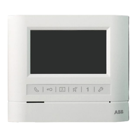
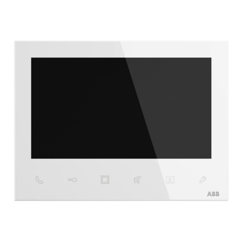
ABB M2231 SERIES User manual

2TMD041600D0107 │16.10.2020
Product manual
ABB-Welcome
M2231.-. 4.3" video hands-free indoor
station

Inhaltsverzeichnis
Product manual
2TMD041600D0107
│
2
Inhaltsverzei chnis
1Notes on the instruction manual............................................................................................................4
2Safety ..................................................................................................................................................4
3Intended use........................................................................................................................................4
4Environment.........................................................................................................................................5
4.1 ABB devices..............................................................................................................................5
5Product description...............................................................................................................................6
5.1 Control elements........................................................................................................................6
5.2 Terminal description...................................................................................................................8
6Technical data......................................................................................................................................9
7Mounting/Installation...........................................................................................................................10
7.1 Requirement for the electrician.................................................................................................10
7.2 General installation instructions................................................................................................11
7.3 Mounting.................................................................................................................................12
7.3.1 Installation height.................................................................................................................. 12
7.3.2 Dismantling.......................................................................................................................... 12
7.3.3 Surface-mounted installation................................................................................................. 13
7.3.4 Flush-mounted installation .................................................................................................... 15
7.3.5 Cavity wall installation........................................................................................................... 17
7.3.6 Desktop installation............................................................................................................... 17
7.3.7 Replace the front cover......................................................................................................... 18
8Commissioning...................................................................................................................................19
8.1 Common operation..................................................................................................................19
8.2 Intercom settings .....................................................................................................................20
8.3 Switch actuator settings...........................................................................................................21
8.4 Program button settings...........................................................................................................22
8.5 Call forward settings ................................................................................................................23
8.6 Auto unlock settings.................................................................................................................24
8.7 Unlock password settings.........................................................................................................25
8.8 Ringtone settings.....................................................................................................................26
8.9 Volume settings.......................................................................................................................27
8.10 Date and time settings.............................................................................................................28
8.11 Other settings..........................................................................................................................29
8.12 Blacklist settings......................................................................................................................30
8.13 History.....................................................................................................................................31
8.14 Camera list..............................................................................................................................32
8.15 Language................................................................................................................................39
8.16 Information..............................................................................................................................40
8.17 Restoring to factory default.......................................................................................................41
9Operation...........................................................................................................................................42
Inhaltsverzeichnis
Product manual
2TMD041600D0107
│
3
9.1 Incoming call ...........................................................................................................................42
9.2 Intercom..................................................................................................................................44
9.3 Call guard unit.........................................................................................................................45
9.4 Broadcast................................................................................................................................46
9.5 Control switch actuator.............................................................................................................47
10 Notice................................................................................................................................................48

Notes on the instruction manual
Product manual
2TMD041600D0107
│
4
1Notes on the instruction manual
Please read through this manual carefully and observe the information it contains. This will
assist you in preventing injuries and damage to property and ensure both reliable operation and
a long service life for the device.
Please keep this manual in a safe place. If you pass the device on, also pass on this manual
along with it. ABB accepts no liability for any failure to observe the instructions in this manual.
2Safety
Warning
Electric voltage!
Dangerous currents flow through the body when coming into direct or indirect
contact with live components.
This can result in electric shock, burns or even death.
– Disconnect the mains power supply prior to installation and/or disassembly!
– Permit work on the 100-240 V supply system to be performed only by
specialist staff!
3Intended use
This device is an integral part of the ABB-Welcome door communication system and operates
exclusively with components from this system. The device must only be installed in dry indoor
rooms.
Cleaning
Caution
Risk of damage to the screen surface
The screen surface can be damaged by hard or sharp objects!
Never use such objects for entries on the touch screen monitor.
– Use your finger or a plastic stylus.
The screen surface can be damaged by cleaning fluids or abrasive agents!
– Clean the surfaces using a soft cloth and commercially available glass
cleaner.
– Never use abrasive cleaning agents.

Environment
Product manual
2TMD041600D0107
│
5
4Environment
Consider the protection of the environment!
Used electric and electronic devices must not be disposed of with household
waste.
– The device contains valuable raw materials that can be recycled. Therefore,
dispose of the device at the appropriate collecting facility.
4.1 ABB devices
All packaging materials and devices from ABB bear the markings and test seals for proper
disposal. Always dispose of the packing materials and electric devices and their components via
an authorized collection facility or disposal company.
ABB products meet the legal requirements, in particular the laws governing electronic and
electrical devices and the REACH ordinance.
(EU-Directive 2012/19/EU WEEE and 2011/65/EU RoHS)
(EU-REACH ordinance and law for the implementation of the ordinance (EG) No.1907/2006)

Product description
Product manual
2TMD041600D0107
│
6
5Product description
5.1 Control elements
No. Description
14.3" Color display
2
Communication button
■When an incoming call, press this button to initiate a communication, press this button again
to end the call.
■In standby status, press this button to initiate an intercom, call guard unit or release the
switch actuator.
– The backlit LED of this button flashes slowly to indicate an incoming call.
– The backlit LED of this button lights on to indicate a conversation is in progress.
– The backlit LED of this button flashes rapidly to indicate system is busy.
3
Unlock button
■Press this button to release the lock at any time.
■Hold this button more than 10 seconds to enable/disable the "Auto-unlock" function. If the
function is enabled, the lock will be released automatically after the indoor station rings 5
seconds andthis function will be available for 10 hours from the moment the function is
enabled.
– The backlit LED of this button lights on to indicate the"Auto-unlock" function is enabled.
– The backlit LED of this button flashes fast to indicate the lock is released over the set time.
4
Surveillance button
■In standby status, press this button to display the image from the default outdoor station,
press this button again to display the next image from other outdoor stations or camera
interfaces.
■When the screen is on, hold this button to take a snapshot manually.
■In standby status, if the backlit LED of this button flashes white, hold this button to view the
missed calls.
1
567432
8

Product description
Product manual
2TMD041600D0107
│
7
No. Description
5
Mute button
■In standby status, press this button to mute the ringtone of this indoor station.
■In standby status, hold this button to mute the ringtone of all indoor stations in the same
apartment.
■When an incoming call, press this button to reject the call.
■During the conversation, press this button to mute the microphone.
– The backlit LED of this button lights on to indicate themute status.
6
Programmable button
■This programmable button is set to release the 2nd lock by default.
■In standby status, hold this button for 3 seconds to send an SOS alarm to the guard unit. The
backlit LED of this button flashes white slowly to indicate success.
■This programmable button can be set to other function e.g. call guard unit, intercom.
7Setting button
In standby status, press this button to enter the system setting screen.
The backlit LED of this button flashes fast to indicate system is busy.
8Induction loop (only for M22343-.)
Induction loop
The induction loop is used for hearing-impaired persons. They can wear a hearing aid to hear
the voice from the outdoor station or the indoor station.
The indoor station supports the hearing aids with "T" function and the maximum distance
between them is around 35 cm.

Product description
Product manual
2TMD041600D0107
│
8
5.2 Terminal description
No. Description
1Station
Select switch to set the address of the default outdoor station.
2
X10 X1
Selector switches to set the address (tens and units digits) of the indoor station.
X200 X100
Dip switches to set the address (hundreds digits) of the indoor station.
3Master/slave function
Only one indoor station in an apartment can be set to "Master" (ON=Master). All other indoor
stations in the same apartmentmust be set to "Slave (OFF=slave).
4Terminal resistor
In video installations or mixed audio and video installations, the switch must be set as ON at
the last device of the bus line.
5a b = BUS connection
doorbell connection
DC GND =Additional power supply
6 Connector to an induction loop
1-9
1
024
2
3
4
6
5

Technical data
Product manual
2TMD041600D0107
│
9
6Technical data
Designation Value
Display resolution 480 x 272
Display size 4.3"
Operating temperature -10 °C…+55 °C
Storage temperature -40 °C…+70 °C
Protection IP 30
Single-wire clamps 2 x 0.28 mm² - 2 x 0.75 mm²
Fine-wire clamps 2 x 0.28 mm² - 2 x 0.75 mm²
Bus voltage 20-30 V
⎓
Size 137 mm x 155 mm x 24 mm

Mounting/Installation
Product manual
2TMD041600D0107
│
10
7Mounting/Installation
Warning
Electric voltage!
Dangerous currents flow through the body when coming into direct or indirect
contact with live components.
This can result in electric shock, burns or even death.
– Disconnect the mains power supply prior to installation and/or disassembly!
– Permit work on the 100-240 V supply system to be performed only by
specialist staff!
7.1 Requirement for the electrician
Warning
Electric voltage!
Install the device only if you have the necessary electrical engineering
knowledge and experience.
– Incorrect installation endangers your life and that of the user of the electrical
system.
– Incorrect installation can cause serious damage to property, e.g. due to fire.
The minimum necessary expert knowledge and requirements for the installation
are as follows:
– Apply the "five safety rules" (DIN VDE 0105, EN 50110):
1. Disconnect
2. Secure against being re-connected
3. Ensure there is no voltage
4. Connect to earth and short-circuit
5. Cover or barricade adjacent live parts.
– Use suitable personal protective clothing.
– Use only suitable tools and measuring devices.
– Check the type of supply network (TN system, IT system, TT system) to
secure the following power supply conditions (classic connection to ground,
protective grounding, necessary additional measures, etc.).

Mounting/Installation
Product manual
2TMD041600D0107
│
11
7.2 General installation instructions
■Terminate all branches of the wiring system via a connected bus device (e.g., indoor station,
outdoor station, system device).
■Do not install the system controller directly next to the bell transformer and other power
supplies (to avoid interference).
■Do not install the wires of the system bus together with 100-240 V wires.
■Do not use common cables for the connecting wires of the door openers and wires of the
system bus.
■Avoid bridges between different cable types.
■Use only two wires for the system bus in a four-core or multi-core cable.
■When looping, never install the incoming and outgoing bus inside the same cable.
■Never install the internal and external bus inside the same cable.

Mounting/Installation
Product manual
2TMD041600D0107
│
12
7.3 Mounting
7.3.1 Installation height
7.3.2 Dismantling
1.50 m (4.9 feet)

Mounting/Installation
Product manual
2TMD041600D0107
│
13
7.3.3 Surface-mounted installation
Surface-mounted box (unit: mm)
Installation
1. Mounted on the wall
114
94
60
83
83
79

M
ounting/Installation
Product manual
2TMD041600D0107
│
14
2. Mounted with flush-mounted box

Mounting/Installation
Product manual
2TMD041600D0107
│
15
7.3.4 Flush-mounted installation
1 Dismantling the frame
2A Mounting with the back cover directly
2B Mounting with the metal flush-mounted box

Mounting/Installation
Product manual
2TMD041600D0107
│
16
3 Latch the upper part

Mounting/Installation
Product manual
2TMD041600D0107
│
17
7.3.5 Cavity wall installation
7.3.6 Desktop installation
1
2
3
4
5

Mounting/Installation
Product manual
2TMD041600D0107
│
18
7.3.7 Replace the front cover

Commissioning
Product manual
2TMD041600D0107
│
19
8Commissioning
8.1 Common operation
No. Functions
1In normal status, press this button to select the previous item.
In setting status, press this button to change the setting or scroll down the letter/number, hold
the button to scroll down the letter/number quickly.
2In normal status, press this button to select the next item.
In setting status, press this button to change the setting or scroll up the letter/number, hold the
button to scroll up the letter/number quickly.
3In normal status, press this button to enter the setting.
In setting status, press this button to confirm the setting.
4In normal status, press this button to turn back to the previous screen.
In setting status, press this button to cancel the setting.
Intercom1
Intercom2
Add New
(001)
1
1
2
3
4
( ) ( )

Commissioning
Product manual
2TMD041600D0107
│
20
8.2 Intercom settings
No. Functions
1Display the existing intercoms.
means an intercom between different apartments.
means an intercom in the same apartment.
2 Click to add a new intercom (maximum 32).
3Call type
In setting status, press "+" or "-" button to set the call type between "External Intercom" and
"Internal Intercom".
4When the call type is set to "External Intercom", in setting status, press "+" or "-" button to set
the address of target indoor station (001-250).
5In setting status, press "+" or "-" button to set a new name.
6In normal status, press "√" button to save the settings.
Intercom1
Intercom2
Add New
(001)
1
2
1
( ) ( )
CallType
Target Address
Rename
INTERCOM
ExternalIntercom
001
mike
Save Cancel
5
4
3
1
6
( ) ( )
Other manuals for M2231 SERIES
2
Table of contents
Other ABB Security System manuals

ABB
ABB 83327-500 User manual

ABB
ABB 83220 AP-5 series User manual

ABB
ABB M2131xPx-A series User manual

ABB
ABB ZMT Zirconia User manual

ABB
ABB Arc Guard System TVOC-2 Product manual

ABB
ABB L240 Series User manual

ABB
ABB L240 Series Guide

ABB
ABB GE GEH4576 User manual

ABB
ABB SACO 16D1 User manual

ABB
ABB Welcome IP H8131.P. Series User manual