ABL eMH1 WALLBOX User manual

VERSION: 5X2-2016-07-15
eMH1
WALLBOX with socket
Instruction Manual
MADE IN
GERMANY
Albert-Büttner-Straße 11
D-91207 Lauf / Pegnitz
Tel. +49 (0) 9123 188-0
Fax +49 (0) 9123 188-188
www.abl.de
ABL SURSUM
Bayerische Elektrozubehör GmbH & Co. KG

ii
Contact
Manufacturer
ABL Sursum
Bayerische Elektrozubehör GmbH & Co. KG
Albert-Büttner-Straße 11
91207 Lauf / Pegnitz
Germany
Phone +49(0)9123 188-0
Fax +49(0)9123 188-188
Web www.abl.de
Email [email protected]
Support Phone +49(0)9123 188-600
Email emobility[email protected]

iii
Contents
Contact . . . . . . . . . . . . . . . . . . . . . . ii
Safety and Operating Notices . . . . . . . . . . . . . . . . . . 1
Safety Notices in this Manual . . . . . . . . . . . . . 1
Safety notices on the device . . . . . . . . . . . . . 1
General safety information . . . . . . . . . . . . . . 2
Operating instructions / Maintenance . . . . . . . . .3
Introduction . . . . . . . . . . . . . . . . . . . . . . . . . . . 5
Product description . . . . . . . . . . . . . . . . . 5
Identifying your product variant . . . . . . . . . . . .6
Package contents and unpacking . . . . . . . . . . .7
Available accessories . . . . . . . . . . . . . . . . 7
Installation and power supply connection . . . . . . . . . . . 9
Prerequisites for the mounting site and installation. . . . 9
Preparation and mechanical installation . . . . . . . 10
Electrical installation of your charging station . . . . . 11
Taking into operation and charging procedure . . . . . . . . 14
Safety information for taking the charging station
into operation . . . . . . . . . . . . . . . . . . 15
Normal operation. . . . . . . . . . . . . . . . . 15
Charging procedure . . . . . . . . . . . . . . . . 16
Resolving errors . . . . . . . . . . . . . . . . . . . . . . . . 17
Operating states . . . . . . . . . . . . . . . . . 17
Error messages during operation with the vehicle . . . 18

iv
Disruptions to the operation of the charging station
and solutions . . . . . . . . . . . . . . . . . . 18
Checking the integrated RCCB (only for model
variants with RCCB) . . . . . . . . . . . . . . . . 20
Taking the device out of operation . . . . . . . . . . 20
Appendix . . . . . . . . . . . . . . . . . . . . . . . . . . . 22
Specifications . . . . . . . . . . . . . . . . . . 22
Trademarks . . . . . . . . . . . . . . . . . . . 24
CE certification and compliance declaration . . . . . . 25
Glossary & Definitions. . . . . . . . . . . . . . . 25
Drilling template . . . . . . . . . . . . . . . . . 26
Warranty and guarantee provisions . . . . . . . . . 27
Disposal advice . . . . . . . . . . . . . . . . . 28

SAFETY AND OPERATING NOTICES
1
Safety and Operating Notices
Safety Notices in this Manual
This instruction manual contains important information for the installation and safe use of the
eMH1 – EVSE 5X2 charging station it refers to. Please ensure therefore that you read and fol-
low the safety notices provided.
In particular, the warnings and safety measures clearly marked in this manual must be followed.
The associated symbols carry the following meanings:
DANGER!
Sections marked with this symbol draw attention to electrical voltages that
represent a danger to life and limb. Actions marked with this symbol must NOT be
carried out UNDER ANY CIRCUMSTANCES.
CAUTION!
Sections marked with this symbol draw attention to further hazards that may
lead to damage to the station itself or to other electric devices. Actions marked with
this symbol must be carried out with SPECIAL CARE.
PLEASE NOTE:
Sections marked with this symbol draw attention to further important infor-
mation and particularities that are necessary for operating the device successfully.
Actions marked with this symbol should be carried out AS REQUIRED.
Safety notices on the device
Further safety notices and operating instructions can be found on the device. These symbols carry
the following meanings:
WARNING!
Please ensure that you read the instruction manual (this document) be-
fore you open the housing of your eMH1 charging station.
WARNING!
After opening, dangerous electrical voltages may be present inside the
housing.

SAFETY AND OPERATING NOTICES
2
WARNING!
Please ensure you read the instruction manual
(this document), before you continue.
In case the charging station is operated by several users, the contents of this manual and the safe-
ty notices in particular must UNDER ALL CIRCUMSTANCES be passed on to each individual user.
General safety information
This device represents the current state of technology and fulfils all technical safety
requirements, guidelines and norms.The safety information provided serves to ensure
the proper operation of the device. Disregard of or actions contrary to the safety infor-
mation and instructions contained in this manual and printed on the device may lead
to electric shock, fire and/or severe injury.
The device may only be operated in technically sound condition. Malfunctions that af-
fect the safety of persons or the device may only be repaired by authorized or qualified
specialist personnel. In case you require service (see next page), always turn first to
the dealer who supplied the device to you.
Service is required when e.g. the housing, the charging socket or the separately avail-
able charging cable are damaged, when liquids or objects have entered the housing,
the device has been directly exposed to rain, has been dropped, otherwise damaged
or is not functioning properly.
• Please pay attention to the following points:
• Read this manual carefully.
• Keep this manual in a safe place where all users can always access it.
• Heed all warnings.
• Follow all instructions.
• Do not operate this device in close vicinity to running water.
• Do not install this device near radiators, heat storage devices, stoves or other sourc-
es of excessive heat.
• Do not step on the power supply cable, do not kink it and treat plugs and sockets
with special care.
• Only use accessories intended and sold for the device by the manufacturer.
• Do not place containers with liquids on the device, as these may tip over and liquids
may enter the device.

SAFETY AND OPERATING NOTICES
3
Operating instructions / Maintenance
Please note the following instructions for the operation and maintenance of your
eMH1 charging station:
• The device must be connected to the protective earth conductor of your electricity
supply.
• Ensure that the rated voltage and rated current of the device comply with the pa-
rameters of your local electricity grid and that the rated output is not exceeded dur-
ing charging operations.
• At all times comply with local safety regulations for the country in which you operate
the device.
• To disconnect the device completely from the power grid, the power supply must
be cut at your domestic miniature circuit breaker (MCB).
• Follow all information and instructions of the manufacturer for installing and operat-
ing the device.
• Do not operate the device in confined spaces.
• Make sure that the front cover shield is always locked to prevent unauthorized open-
ing of the housing. Keep the key in a place that is known to all authorized users.
• You must NOT UNDER ANY CIRCUMSTANCES make any changes to the housing
or the internal wiring of the device: Any disregard of this instruction fundamentally
breaches the guarantee provisions and voids the warranty with immediate effect.
• No parts to be maintained by the user are located inside the device.
• Only have qualified, specialist personnel repair and/or install the device.
WARNING!
This charging station is intended for connection to and operation on 230
V 50 Hz or 230 / 400 V 50 Hz mains power only. Power supply cables
may be installed below or above the wall surface. The cable should enter
the device on the underside of the bottom part of the housing (see page
11).
• Only use a dry cloth to clean the device. Do not use aggressive cleaning agents,
waxes or solvents (such as cleaning fluid or paint thinner), because they can dull the
displays on the device.
• The charging station MUST NEVER be cleaned using a pressure cleaner or similar
implement.
• Regularly check the charging socket and the separately available charging cable of
your eMH1 charging station for wear and tear. Pay special attention to the proper fit
of the connectors of the charging cable in the charging sockets of both the eMH1
and the vehicle.

SAFETY AND OPERATING NOTICES
4
DANGER!
Should you discover any damage to the charging cable or a supply ca-
ble, you must take the device out of operation immediately. In this case,
please turn to an authorized service partner or the dealer from whom you
purchased the product. You must NOT UNDER ANY CIRCUMSTANCES
attempt to resolve or repair any damage of malfunction yourself!
Relevant local regulations for operating electrical devices always apply.

INTRODUCTION
5
Introduction
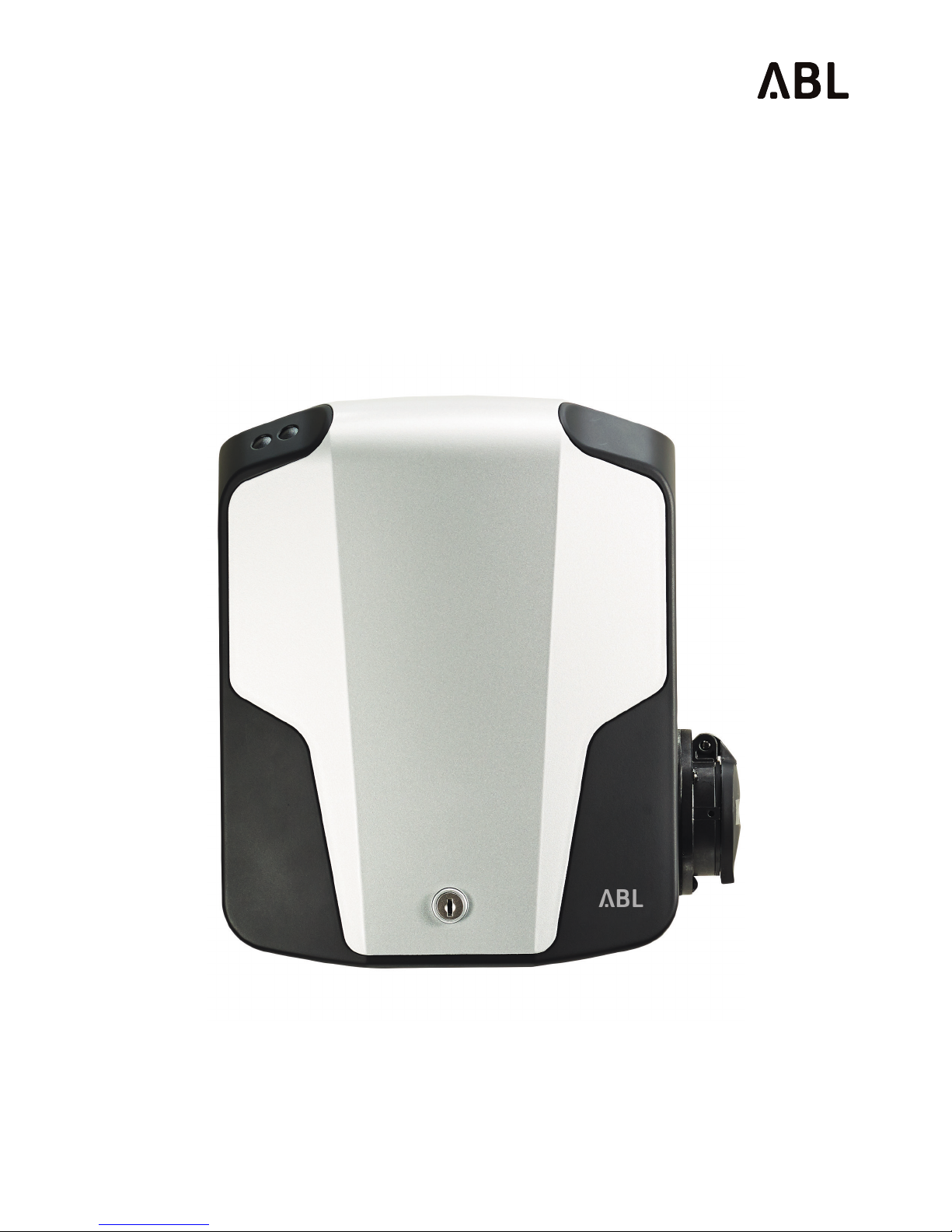
Congratulations on the purchase of your eMH1 charging station by ABL!
With this charging station from our “Electric Mobility Home“ series, you have chosen an innovative
as well as future-proof product that guarantees particularly high operating safety while featuring
extremely compact dimensions.
eMobility helps to save natural resources and protect the environment sustainably. ABL is, with
its eMH1 family of products, a leading supplier in this area. The eMH1 combines progressive and
pleasing design with intuitive functionality: According to their requirements, users may select from
models with a variety of features developed for domestic and semi-public applications.
The eMH1 series charging stations are constantly developed further and at all times
comply with the regulations and norms for the charging of electric vehicles applicable
throughout Europe according to IEC 61851-1, Mode 3.
If you are looking for additional information about your charging station or would like
to find out more about available accessories and the remaining ABL product range,
please visit our website at
www.abl.de
Product description
Your eMH1 charging station allows you to comfortably and safely charge electric ve-
hicles according to IEC 61851-1, Mode 3. Switching layout and charging connectors of
the eMH1 are designed for the shortest possible charging times.
We place the highest value on user safety in all our products. Your eMH1 wall box
therefore features an integrated residual current circuit breaker (RCCB) and/or an inte-
grated DC fault current detector (depending on the model variant). In combination with
the protection devices of your electrical infrastructure and the fault current protection
of your electric vehicle, these measures ensure effective protection against short cir-
cuit, electric shock and other operational hazards.
The eMH1 charging station is especially easy to operate in day-to-day use: Two LED
lights in the upper part of the housing allow you to check the current operating status
at any time. Should a malfunction occur, you can identify the cause by its specific LED
error code without having to open the housing. Access to the internal switching de-
vices is controlled through the lockable cover shield – this way you can ensure that the
housing can only be opened by authorized users.
A common characteristic of all eMH1 models is the particularly space-saving housing made from
durable plastic, which effectively protects the internal electric circuits against environmental influ-
ences and unauthorized access. In general, all model variants of the EVSE5X2 series should be
installed and taken into operation by a qualified electrical contractor. Your local distributor will be
happy to arrange specialist installation for you at your desired location.

INTRODUCTION
6
Identifying your product variant
The eMH1 series comprises several model variants, which are mechanically and/or
electrically adapted to different usage profiles. For identification, a product compliance
plate is located at the back of the lockable housing cover shield near the hinge. Please
open the cover shield before taking the device into operation and check the compli-
ance plate to ensure that the model variant you have installed is the one described in
this manual.
(Illustration is approximate)
For identification, the model code
(EVSE XXX) as well as the power sup-
ply ratings (voltage, frequency, cur-
rent) indicated below it are especially
relevant.
The following charging stations are described in this manual:
MODEL POWER SUPPLY MODEL VARIANT
EVSE 502 230 / 400 V
50 Hz 16 A
Integrated charging socket according to IEC 62196-2, Type 2
with locking mechanism for separately available charging cable
(Type 2 to Type 2 or Type 2 to Type 1); integrated RCCB Type A;
integrated DC fault current detector; charging output 11 kW
EVSE 512 230 V / 50 Hz / 32 A Single phase EVSE 502 model variant without integrated DC
fault current detector; charging output 7.2 kW
EVSE 522 230 / 400 V
50 Hz 16 A
Integrated charging socket according to IEC 62196-2, Type 2
with locking mechanism for separately available charging cable
(Type 2 to Type 2 or Type 2 to Type 1); integrated RCCB Type B;
charging output 11 kW
EVSE 552 230 / 400 V
50 Hz 32 A
3 phase EVSE 512 model variant with onsite RCCB required;
approved by TESLA MOTORS GmbH, charging output 22 kW
EVSE 562 230 V / 50 Hz / 32 A Construction identical to the EVSE 512 model variant but onsite
RCCB required
; charging output 7,2 kW
EVSE 572 230 V / 50 Hz / 32 A Construction identical to the EVSE 512 model variant but with
integrated DC fault current detector; charging output 7.2 kW
WARNING!
The information and technical specifications contained in this manual re-
late exclusively to the model variants mentioned in these instructions
and must UNDER NO CIRCUMSTANCES be transferred to other eMH1
models.
099999
14-12-23
EVSE502
230/400V 50Hz 16A
IP44
IEC 61851-1
IEC 61439-7 ACSEV

INTRODUCTION
7
Package contents and unpacking
Your eMH1 charging station is delivered with a range of accessory components, which
are necessary for the proper operation of the device. Therefore, please check immedi-
ately after unpacking whether the following components are included:
COMPONENT QUANTITY DESCRIPTION
eMH1 charging
station 1
Charging station comprising lower and upper
housing part and cover shield with integrated
lock
Instruction Manual 1Manual for operating the charging station (this
document)
Key 2
Key for locking the housing cover shield
Drilling template 1Template for drilling the holes for wall mounting
Should one or more components be missing after unpacking, please contact your local
distributor immediately: You can find the necessary contact details on page ii in
this manual.
Available accessories
ABL sells additional accessories for your eMH1 charging station. For the models of the
EVSE 5X2 series, the following components are available:
DESIGNATION PART NUMBER QUANTITY
Type 2 charging cable
for connection with all eMH1 charging stations
and vehicles with charging sockets according to
IEC 62196-2, Type 2, 32 A 240 / 415 V AC and
IP44 splash protection rating
Length: approx. 4 meters
LAK32A3 1
Adapter cable Type 2 to Type 1
for connection to all eMH1 charging stations with
charging sockets according to IEC 62196-2, Type 2,
with charging connector according to IEC 62196-2,
Type 1, 32 A 230 V AC, and IP44 splash protection
rating
Length: approx. 4 meters
LAKT2T1 1

INTRODUCTION
8
DESIGNATION PART NUMBER QUANTITY
Mounting pole*
For mounting all eMH1 charging stations with or
without bracket
Dimensions: 1600 x 280 x 70 cm Weight: 2,000 g
STEMH10 1
Mounting plate / bracket
with fixings for all eMH1 charging stations
Weight: 640 g
WHEMH10 1
* does not include the charging station pictured
Please contact your local distributor if you require additional information about these
components or would like to place an order.
CAUTION!
Please note that the do-it-yourself installation of accessory components
is not permitted: Please contact a qualified contractor or arrange installa-
tion with your local distributor
.
Please also visit our website at...
www.abl.de
You will find further information about our products and our entire product range there.

INSTALLATION AND POWER SUPPLY CONNECTION
9
Installation and power supply connection
The electrical installation of the eMH1 charging station model variants described in this
manual must always be carried out by qualified specialist personnel: Please contact an
electrical contractor or arrange installation at your premises with your local distributor.
However, as a user you may carry out the mechanical installation of the charging sta-
tion yourself, as long as you follow the safety notices and general instructions.
Prerequisites for the mounting site and installation
Your eMH1 charging station is an electrical device and is therefore subject to particular
prerequisites for indoor and outdoor installation: Although the housing of the eMH1
complies with the standards for the IP44 degree of protection, you must take into ac-
count certain environmental conditions, especially outdoors.
In selecting the mounting site you must consider the following points:
• For the safe operation of your charging station, minimum distances to other tech-
nical installations must be observed: You can obtain further information from your
electrical contractor or your distributor.
• The charging station must be installed where it is freely accessible to all authorized
users.
• Ideally, the mounting site should already provide a connection to the power supply.
If not, a separate supply must be installed that complies with the generally pre-
scribed standards for cabling and building infrastructure: Please contact a qualified
electrical contractor for details.
WARNING!
The power supply for the eMH1 must ALWAYS be protected by a domes-
tic miniature circuit breaker (MCB) .
Some model variants require the supply cable to be protected by an addi-
tional external FI residual current circuit breaker (RCCB). Further informa-
tion available under Technical Data, see page 11.
• This charging station is intended exclusively for connection to and operation on a
rated voltage of 230 V 50Hz ( EVSE 512 / 562 / 572) or 230/ 400 V 50 Hz (EVSE 502/
522 / 552).
• The power supply cables may be installed above or below the wall surface. How-
ever, the cable should preferably enter the device through the inlet on the underside
of the bottom part of the housing.
• Sufficient air circulation must be ensured at the mounting site so that the charging
station is cooled during operation: Always observe the allowed operating tempera-
tures (see “Specifications” on page 22).

INSTALLATION AND POWER SUPPLY CONNECTION
10
• Do not install or operate the charging station in direct sunlight, as it could overheat
and/or the housing could be damaged over time.
DANGER!
In case of visible damage to the charging station occurring during instal-
lation or use, the device must be taken out of operation immediately, as
this poses a danger to life and limb. In this case, replacement of the charg-
ing station is required!
• Outdoors the charging station should only be installed in covered
locations that provide sufficient protection from rainwater. Instal-
lation in a garage or carport is recommended, as long as it fulfills
the stated requirements.
• The recommended installation height is 50 to 150 cm from the
floor to the lower edge of the housing.
• The required mounting area for the model variants of the eMH1
charging station described in this manual is at least 262 x 222mm
(H x W).
• The mounting area must have an even surface that provides suf-
ficient stability for installing the eMH1.
• Choose a mounting site that allows you to reach the charging
socket of your vehicle comfortably with the charging connector of
the eMH1: The cable must NOT UNDER ANY CIRCUMSTANCES
be strained when connected to the vehicle.
Preparation and mechanical installation
After determining the mounting site for the eMH1, you can begin with the mechanical
installation. For installation you will need the following components:
• Power drill or cordless drill (not included)
• Drill bit Ø 8 mm, appropriate for the wall material (not included)
• Pliers or cutter for breaking or cutting out the cable inlet in the rear part of the hous-
ing of the eMH1 (not included)
• Three flat-headed screws size M5 x 60, fully or partly threaded, with a head diam-
eter of 8.5 mm ± 1 mm (not included)
• Nylon wall plugs 8 x 40 mm suitable for the wall material (not included)
• Drilling template for the eMH1 model variants described in this manual (included)
• Spirit level if required (not included)
50 to
150 cm

INSTALLATION AND POWER SUPPLY CONNECTION
11
CAUTION!
Check the measurements on the drilling template with a calibrated
measuring tape BEFORE you mark the drill holes using the tem-
plate and then drill them
.
Drilling the mounting holes using the drilling template
Proceed as follows to drill the holes using the drilling template:
1. Place the drilling template vertically on the mounting surface, using a spirit level if
necessary.
2. Mark the drill holes using the template.
3. Drill the marked mounting holes (Ø 8 mm) and check the positions of the holes us-
ing the drilling template.
4. Insert the wall plugs for the mounting screws.
Preparing the charging station
Proceed as follows to prepare the charging station for installation:
1. Open the cover shield of the EVSE 5X2 using the key supplied.
2. Loosen the four screws connecting the front part of the housing with the rear part:
Keep the screws in a safe place as you will need them again to complete installa-
tion.
3. Pull off the front part of the housing.
4. Remove the plastic tongue intended for the power supply in the lower section of
the rear part of the housing using a suitable pair of pliers or a cutter.
5. Use the cutter to cut an opening to suit the power supply cable into the rubber
seal of the rear part of the housing. If necessary, remove the rubber seal for this
purpose and place it back into the rear part of the housing afterwards.
Mechanical installation of the charging station
1. Fix one screw (5 x 60 mm, screw head Ø 8 mm) in the top drill hole and hang the
upper mounting point of the charging station on it.
2. Fix the two lower mounting points using the other two screws (5 x 60 mm, screw
head Ø 8 mm).
3. Tighten the two lower screws so that the rear part of the housing is held in place
without being deformed by the tension applied to the mounting points.
Electrical installation of your charging station
The electrical connection of the EVSE 5X2 to your domestic power supply and taking

INSTALLATION AND POWER SUPPLY CONNECTION
12
it into operation must always be carried out by a qualified person or specialist electri-
cal contractor. All local norms and regulations regarding the installation of electrical
devices must be observed.
WARNING!
Read and make sure that you follow all safety notices in this manual and
those on the charging station itself!
Now turn off the miniature circuit breaker (MCB) in your domestic power distribution
box before you insert the power supply cable into the EVSE 5X2 housing: The power
supply cable must be voltage-free under all circumstances before you or any third per-
son open the housing and/or manipulate the power supply in any way.
DANGER!
Under all circumstances deactivate the miniature circuit breaker (MCB) al-
located to the eMH1 in your domestic power distribution box before you
begin electrical installation. Also ensure that the MCB cannot be reacti-
vated during installation. Otherwise there is a danger of electric shock!
n addition, depending on your model variant, please deactivate the integrated or exter-
nal residual current circuit breaker (RCCB) to disconnect the internal electronics from
the power supply during installation. Depending on the model variant, the RCCB is
either integrated or must be placed upstream of the supply cable. Further information
available under Technical Data, see page 22.
Insert the power supply cable through the lower cable inlet into the housing and fix the
cable using the internal strain relief clamp.
For all single phase EVSE model variants, the power supply is connected as follows:
DESIGNATION WIRE COLORS CONNECTION CODING
Current-carrying conductor BROWN L1
Neutral BLUE N
Protective earth GREEN-YELLOW PE
For all 3-phase EVSE model variants, the power supply is connected as follows:
DESIGNATION WIRE COLORS CONNECTION CODING
Current-carrying conductor phase 1 BROWN L1
Current-carrying conductor phase 2 BLACK L2
Current-carrying conductor phase 3 GRAY L3
Neutral BLUE N
Protective earth GREEN-YELLOW PE

INSTALLATION AND POWER SUPPLY CONNECTION
13
DANGER!
The above color-coding is NOT internationally standardized: Should the in-
dividual wires in the power supply cable be color-coded differently, please
immediately contact a qualified electrical contractor! Have the power
supply checked and replaced if necessary.
After successful connection to the power supply by a qualified specialist or electrical
contractor, please take the following steps to complete installation:
1. Replace the upper part of the housing.
2. Fix the upper part of the housing to the rear part using the appropriate screws.
3. Switch the integrated or onsite FI residual current circuit breaker (RCCB) back on.
4. Lock the cover shield of the EVSE 5x2 using the key supplied and store the key in
a safe place.
5. Switch the MCB in your domestic power distribution box back on.
PLEASE NOTE:
We recommend that you take your charging station into operation in the
presence of a qualified installer: He or she will be able to assess the
proper functioning of the charging station and correct any malfunctions
or installation errors that may occur.

TAKING INTO OPERATION AND CHARGING PROCEDURE
14
Taking into operation and charging procedure
Your charging station is ready for use immediately after mechanical and electrical in-
stallation have been completed. The EVSE 5X2 features a charging socket according
to IEC 62196-2, Type 2. Accordingly, you will require a (separately available) charging
cable to connect your vehicle. To provide a high level of flexibility, ABL has two differ-
ent cables on offer for this purpose:
PART NUMBER DESCRIPTION MAXIMUM OUTPUT
LAK32A3
Type 2 charging cable for connecting all eMH1
charging stations and vehicles with charging
sockets according to IEC 62196-2, Type 2
22 kW
LAKT2T1
Adapter cable Type 2 to Type 1 for connection to
all eMH1 charging stations with charging sock-
ets according to IEC 62196-2,Type 2, with charg-
ing connector according to IEC 62196-2, Type 1
7.4 kW
The charging socket of the EVSE 5X2 has three current-carrying contacts, a neutral
conductor, a PE-protective earth conductor as well as two signaling contacts (Control
Pilot and Proximity Pilot), which ensure a secure connection and therefore the safe
operation of the charging station.
The charging socket of the EVSE 5X2 has an electromechani-
cal locking mechanism, which secures the charging plug
in place as soon as the charging cable is connected to
the vehicle. As long as the plug of the external charging
cable is not locked into place in the charging socket of
the EVSE 5X2, the charging process cannot be initiated
and no voltage will be applied from the socket to the
charging cable via the current-carrying contacts.
Some model variants come with a built-in DC-moni-
toring unit (DC-RCM): This module ensures that no DC
fault current (DC current > 6 mA) can reach the domestic
power installations and disrupt the proper functioning of the upstream domestic re-
sidual current circuit breaker (RCCB) during vehicle charging. This circuit breaker is
especially required in cases where your electric vehicle does not provide any DC fault
current protection itself: You can find information about this in the manual for your ve-
hicle and from the manufacturer or vehicle dealership.
WARNING!
Ensure that your vehicle has internal DC fault current protection: Depend-
ing on the country where you operate the eMH1, charging using the
model variants without integrated DC-RCM may only be permitted with
an external, upstream type B RCCB! Otherwise, all local regulations for
connection to the power supply must be observed.

TAKING INTO OPERATION AND CHARGING PROCEDURE
15
Safety information for taking the charging station into operation
Before you take your EVSE 5X2 charging station into operation, you must observe the
following safety notices:
• Ensure that the EVSE 5X2 is connected to the domestic power supply according to
the instructions in this manual and the separately available service guide.
• Ensure that the EVSE 5X2 is separately protected in your domestic power distribu-
tion box by a suitable miniature circuit breaker (MCB, C characteristic).
• Ensure that the integrated or onsite (depending on model variant) FI residual current
circuit breaker (RCCB) is switched on.
• Ensure that the EVSE 5X2 has been installed according to the instructions in this
manual: Check especially that there is free access to the charging station, that it is
not exposed to direct sunlight or rain and that the electric vehicle can be connected
without any strain or other encumbrance on the charging cable.
• Ensure that the housing cover shield of the EVSE 5X2 is always locked during normal
operation.
• Ensure that the separately available charging cable is not twisted and check that
cable, connector and housing do not show any observable damage.
Normal operation
On the right side of the housing, the EVSE 5X2 is fitted with a charging socket accord-
ing to IEC 62196-2, Type 2 with electromechanical locking function. To protect against
faulty charging as well as possible electric shock, the charging plug is locked in the
charging socket as soon as the charging cable is properly connected to both charg-
ing station and electric vehicle. The lock is released only after the charging process is
complete, when a voltage is no longer applied to the current-carrying contacts of the
socket.
A charging cable (available separately) is required for the charging process itself. The
models available from ABL are listed on page 7 and you can obtain further informa-
tion on the ABL website at
www.abl.de
as well as from your local distributor.
The separately available charging cable for the EVSE 5X2 is 4 approx. meters long to
offer a flexible connection between charging station and vehicle. In practice it is advis-
able to remove the charging cable after each charging process. Should you wish to
store the cable near the charging station, it is recommended that you install the sepa-
rately available wall storage bracket WHEMH10 (see page 7) as well. Now you can
roll the cable up tightly and hang it on the cable hanger of the WHEMH10: This way it
is always close at hand.

TAKING INTO OPERATION AND CHARGING PROCEDURE
16
Although the cable and connector are designed to withstand high mechanical stress-
es, you should not drive your vehicle over the cable and/or the connector. Also ensure
that the cable is not kinked at the charging socket and that there is no excessive strain
on the cable and/or the housing.
DANGER!
Ifthecable,thechargingconnectorand/orthehousinghavesufferedmechan-
ical damage or show visible deformities, you must under no circumstances
continue to operate the charging station.
Please contact your local distributor from whom you have purchased the
charging station.
Charging procedure
The EVSE 5X2 is engineered for the fastest possible charge of your vehicle according
to IEC 61851-1, Mode 3. The actual charging time depends on the battery fitted to your
vehicle as well as on the energy currently remaining in the vehicle. For these reasons
it is not possible to make a reliable prediction of the charging time: You will discover its
actual value in practice and derive your personal charging routine accordingly.
Please follow the following steps to charge your vehicle:
1. Check the two indicator LEDs on the top part of the EVSE 5X2: When the charging
station is ready for operation, the green LED indicator will flash briefly every 5 sec-
onds, while the blue LED will be not be illuminated.
2. Open the charging socket on the vehicle.
3. Plug the charging connector of the charging cable (Type
2 or Type 1) into the vehicle’s charging socket. The ve-
hicle must be positioned so that you can reach the ve-
hicle socket comfortably. The cable must not be strained
during the charging process.
4. Open the cover of the charging socket on the EVSE 5X2
and plug in the Type 2 charging connector.
The green LED will be illuminated continuously while the connection between charg-
ing station and vehicle is being established. When the charging procedure begins, the
green LED will be extinguished and the blue LED will be illuminated continuously.
Charging is completed when the blue LED is flashing.
PLEASE NOTE:
Should a malfunction occur during or after the charging process, this will
be indicated by the LEDs on top of the housing. The following chapter
describes how you can identify operational states and errors and which
measures will become necessary.
When charging is complete, unplug the cable from the vehicle socket and from the
socket of the charging station and store it for the next charging procedure.
Other manuals for eMH1 WALLBOX
8
Table of contents
Other ABL Batteries Charger manuals