Abov MC80F0304 User manual

ABOV SEMICONDUCTOR
8-BIT SINGLE-CHIP MICROCONTROLLERS
MC80F0304/0308/0316
MC80C0304/0308/0316
User’s Manual (Ver. 2.12)

Version 2.12
Published by
FAE Team
©2006 ABOV Semiconductor Co., Ltd. All right reserved.
Additional information of this manual may be served by ABOV Semiconductor offices in Korea or Distributors and Representatives.
ABOV Semiconductor reserves the right to make changes to any information here in at any time without notice.
The information, diagrams and other data in this manual are correct and reliable; however, ABOV Semiconductor is in no way responsible
for any violations of patents or other rights of the third party generated by the use of this manual.

MC80F0304/08/16
November 4, 2011 Ver 2.12 3
REVISION HISTORY
VERSION 2.12 (November 4, 2011) This Book
Logo is changed.
The dimensions of 28 SOP package outline drawing is fixed.
VERSION 2.11 (May 14, 2008)
Corrected Stack End Address to 0100Hat Figure 8-4 on page 34.
Corrected the address of PU2 to 00FEHat Figure 8-1 on page 38.
Corrected the bit name of TM1to T1CK1,T1CK0,T1CN and T1ST at Figure 13-17 on page 75.
Corrected the PWM1HR to T1PWHR at Figure 13-20 on page 77.
Corrected the initial value of WDT Timer to “Enable” at Figure 20-1 on page 110.
VERSION 2.10 (April 4, 2008)
Updated the description for Figure 14-4 A/D Converter Control & Result Register on page 80.
The format of Instruction Set and Revision History was renewed.
Fixed some errata.
VERSION 2.02 (SEP 28, 2007) This book
Fix error in description and diagram of 8 bit event counter.
VERSION 2.01 (MAY 5, 2007)
Fix error in figure 9-2 : change R04, R07 and EC0,EC1 of PSR1 to R05, R06 and T0O, T2O (page 38)
Fix pin number error of 28 pin package in Table 5-2. (page 9)
VERSION 2.0 (MAR. 2007)
Add TVDD parameter specification and change TPOR in DC Electrical Characteristics.
Note for configuration option is added and fix some errata.
VERSION 1.92 (JAN. 2007)
Mask Order Sheet is updated
VERSION 1.91 (NOV. 2006)
Fix some errata in Section 13.6 PWM mode.
VERSION 1.9 (SEP. 2006)
Add 32 SOP package type.
VERSION 1.81 (AUG. 2006)
Fix some errata in Figure 18-2 and Figure 18-3.
VERSION 1.8 (JUL. 2006)
Correct Interrupts Sequence and example codes in Chapter 18.
Mask Order Sheet is updated

MC80F0304/08/16
4 November 4, 2011 Ver 2.12
Delete chapter 15.3.
Fix some errata.
VERSION 1.7 (JUN. 2006)
Correct the description of TM1 in Figure13-1.
fXIN/2, fXIN/8 and timer0 clock instead of fXIN/4, fXIN/16 and timer2 clock are selected when T1CK[1..0] is “01b”, “10b”,
“11b” respectively.
VERSION 1.6 (MAY.2006)
Update notification in Chapter 26.3 Hardware Conditions to Enter the ISP Mode. (Condition to enter ISP in case of using
RESET pin as input pin)
Correct the schematic of ISP configuration and Reference ISP Board circuit.
Add chapters about sequence to enter ISP/User mode and ACK mode and update chapters 26.3 to chapter 26.6
Fix some font error in chapter 25. Emulator Board Setting.
VERSION 1.5 (APR. 2006)
Update Typical Characteristics
VERSION 1.4 (APR. 2006)
Correct SIO Block diagram, Timing and usage.
VERSION 1.3 (MAR. 2006)
The company name, MagnaChip Semiconductor Ltd. changed to ABOV Semiconductor Co.,Ltd..
Add 28 SOP package type.
VERSION 1.2 (OCT. 2005)
Add notification that the DAA, DAS decimal adjust instructions are not supported.
VERSION 1.1 (JUN. 2005)
Add Pb free package
VERSION 1.0 (MAY. 2005)
Fix some errata.
VERSION 0.1 (MAR. 2005)
First Edition.

MC80F0304/08/16
November 4, 2011 Ver 2.12 5
Table of Contents
1. OVERVIEW.........................................................7
Description .........................................................7
Features .............................................................7
Development Tools ............................................8
Ordering Information ........................................9
2. BLOCK DIAGRAM ...........................................10
3. PIN ASSIGNMENT ...........................................11
4. PACKAGE DRAWING .....................................12
5. PIN FUNCTION ................................................16
6. PORT STRUCTURES ......................................18
7. ELECTRICAL CHARACE TERISTICS ............22
Absolute Maximum Ratings .............................22
Recommended Operating Conditions ..............22
A/D Converter Characteristics .........................22
DC Electrical Characteristics ...........................23
AC Characteristics ...........................................24
Typical Characteristics (MC80F0304/08/16) ....24
Typical Characteristics (MC80C0304/08/16) ...28
8. MEMORY ORGANIZATION .............................32
Registers ..........................................................32
Program Memory .............................................34
Data Memory ..................................................37
Addressing Mode .............................................41
9. I/O PORTS........................................................46
R0 and R0IO register .......................................46
R1 and R1IO register .......................................47
R2 and R2IO register .......................................48
R3 and R3IO register .......................................49
10.CLOCK GENERATOR .....................................51
Oscillation Circuit ............................................51
11.BASIC INTERVAL TIMER................................53
12.WATCHDOG TIMER ........................................55
13.TIMER/EVENT COUNTER ...............................58
8-bit Timer / Counter Mode ..............................61
16-bit Timer / Counter Mode ............................65
8-bit Compare Output (16-bit) ..........................67
8-bit Capture Mode ..........................................67
16-bit Capture Mode ........................................72
PWM Mode ......................................................74
14.ANALOG TO DIGITAL CONVERTER .............78
15.SERIAL INPUT/OUTPUT (SIO)........................81
Transmission/Receiving Timing ...................... 82
The usage of Serial I/O ................................... 83
16.UNIVERSAL ASYNCHRONOUS RECEIVER/
TRANSMITTER (UART) .................................. 85
UART Serial Interface Functions ..................... 85
Serial Interface Configuration .......................... 86
Communication operation ............................... 89
Relationship between main clock and baud rate .
90
17.BUZZER FUNCTION ....................................... 92
18.INTERRUPTS .................................................. 94
Interrupt Sequence .......................................... 96
BRK Interrupt .................................................. 98
Multi Interrupt .................................................. 98
External Interrupt ............................................. 99
19.POWER SAVING OPERATION .................... 102
Sleep Mode ................................................... 102
Stop Mode ..................................................... 103
Stop Mode at Internal RC-Oscillated Watchdog
Timer Mode ................................................... 106
Minimizing Current Consumption .................. 107
20.RESET ........................................................... 110
21.POWER FAIL PROCESSOR......................... 112
22.COUNTERMEASURE OF NOISE ................. 114
Oscillation Noise Protector ............................ 114
Oscillation Fail Processor .............................. 115
23.DEVICE CONFIGURATION AREA ............... 116
24.MASK OPTION (MC80C0304/08/16) ............ 117
25.EMULATOR EVA. BOARD SETTING ......... 118
DIP Switch and VR Setting ........................... 119
26.IN-SYSTEM PROGRAMMING (ISP) ............. 121
Getting Started / Installation .......................... 121
Basic ISP S/W Information ............................ 121
Hardware Conditions to Enter the ISP Mode 122
Sequence to enter ISP mode/user mode ...... 124
ACK mode ..................................................... 124
Reference ISP Circuit Diagram and ABOV Sup-
plied ISP Board ............................................. 124
A. INSTRUCTION.................................................. ii
Terminology List ................................................ii
Instruction Map ................................................. iii
Instruction Set ..................................................iv
MC80F0304/08/16
6 November 4, 2011 Ver 2.12
B. MASK ORDER SHEET(MC80C0304)...............x
C. MASK ORDER SHEET(MC80C0308)..............xi
D. MASK ORDER SHEET(MC80C0316) ............ xii

MC80F0304/08/16
November 4, 2011 Ver 2.12 7
MC80F0304/0308/0316
MC80C0304/0308/0316
CMOS SINGLE-CHIP 8-BIT MICROCONTROLLER
WITH 10-BIT A/D CONVERTER AND UART
1. OVERVIEW
1.1 Description
The MC80F0304/0308/0316 is advanced CMOS 8-bit microcontroller with 4K/8K/16K bytes of FLASH. This is a powerful microcontrol-
ler which provides a highly flexible and cost effective solution to many embedded control applications. This provides the following features
: 4K/8K/16K bytes of FLASH, 512 bytes of RAM, 8/16-bit timer/counter, watchdog timer, 10-bit A/D converter, 8-bit Serial Input/Output,
UART, buzzer driving port, 10-bit PWM output and on-chip oscillator and clock circuitry. It also has ONP, noise filter, PFD for improving
noise immunity. In addition, the MC80F0304/0308/0316 supports power saving modes to reduce power consumption.
This document explaines the base MC80F0316, the other’s eliminated functions are same as below table.
1.2 Features
• 4K/8K/16K Bytes On-chip ROM
• FLASH Memory
- Endurance : 1000 cycles
- Data retention time : 10 years
• 512 Bytes On-chip Data RAM
(Included stack memory)
• Minimum Instruction Execution Time:
- 333ns at 12MHz (NOP instruction)
• Programmable I/O pins
(LED direct driving can be a source and sink)
- MC80F0316B : 30(29)
- MC80F0316D32 : 30(29)
- MC80F0316G : 26(25)
- MC80F0316D : 26(25)
• One 8-bit Basic Interval Timer
• Four 8-bit Timer/counters
(or two 16-bit Timer/counter)
• One Watchdog timer
• Two 10-bit High Speed PWM Outputs
• 10-bit A/D converter : 16 channels
• Two 8-bit Serial Communication Interface
- One Serial I/O and one UART
• One Buzzer Driving port
- 488Hz ~ 250kHz@4MHz
• Four External Interrupt input ports
• On-chip POR (Power on Reset)
• Thirteen Interrupt sources
- External input : 4
- Timer : 6
- A/D Conversion : 1
- Serial Interface : 1
- UART : 1
• Built in Noise Immunity Circuit
- Noise filter
- PFD (Power fail detector)
- ONP (Oscillation Noise Protector)
• Power Down Mode
- Stop mode
- Sleep mode
- RC-WDT mode
• Operating Voltage & Frequency
Device Name FLASH
Size RAM ADC I/O PORT Package
FLASH MASK ROM
MC80F0304B/08B/16B MC80C0304B/08B/16B
4K/8K/16K 512B 16 channel
30 port 32 PDIP
MC80F0304D32/
08D32/16D32
MC80C0304D32/
08D32/16D32 30 port 32 SOP
MC80F0304G/08G/16G MC80C0304G/08G/16G 26 port 28 SKDIP
MC80F0304D/08D/16D MC80C0304D/08D/16D 26 port 28 SOP

MC80F0304/08/16
8 November 4, 2011 Ver 2.12
- 2. 7 V ~ 5. 5 V ( at 1 ~ 8 M Hz ) : F L AS H
- 2.0V ~ 5.5V (at 1 ~ 4.2MHz) : MASK
- 4.5V ~ 5.5V (at 1 ~ 12MHz) : FLASH,MASK
• Operating Temperature : -40°C ~ 85°C
• Oscillator Type
- Crystal
- Ceramic resonator
- External RC Oscillator (C can be omitted)
- Internal Oscillator (4MHz/2MHz)
• Package
- 28SKDIP, 28SOP, 32PDIP
- Avalilable Pb free package
1.3 Development Tools
The MC80F0304/0308/0316 is supported by a full-featured mac-
ro assembler, an in-circuit emulator CHOICE-Dr.TM and OTP
programmers. There are two different type of programmers such
as single type and gang type. Macro assembler operates under the
MS-Windows 95 and upversioned Windows OS.
Please contact sales part of ABOV semiconductor.
Software
- MS-Windows based assembler
- MS-Windows based Debugger
- HMS800 C compiler
Hardware
(Emulator)
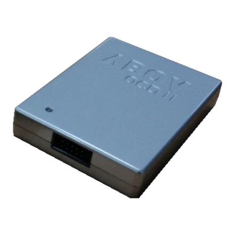
- CHOICE-Dr.
- CHOICE-Dr. EVA80C0x B/D
FLASH Writer
- CHOICE - SIGMA I/II (Single writer)
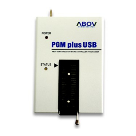
- PGM Plus III (Single writer)
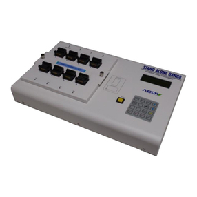
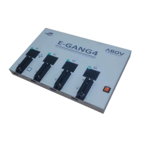
- Standalone GANG4 I/II (Gang writer)
PGMplus III ( Single Writer )
Choice-Dr. (Emulator)
Standalone Gang4 II ( Gang Writer )

MC80F0304/08/16
November 4, 2011 Ver 2.12 9
1.4 Ordering Information
Pb free package:
The “P” Suffix will be added at the original part number.
For example; MC80F0316G(Normal package), MC80F0316G P(Pb free package)
Device name MASK ROM FLASH ROM RAM Package
MASK version
MC80C0316B
MC80C0316D32
MC80C0316G
MC80C0316D
16K bytes
16K bytes
16K bytes
16K bytes
-
512bytes
32PDIP
32SOP
28SKDIP
28SOP
MC80C0308B
MC80C0308D32
MC80C0308G
MC80C0308D
8K bytes
8K bytes
8K bytes
8K bytes
512bytes
32PDIP
32SOP
28SKDIP
28SOP
MC80C0304B
MC80C0304D32
MC80C0404G
MC80C0304D
4K bytes
4K bytes
4K bytes
4K bytes
512bytes
32PDIP
32SOP
28SKDIP
28SOP
FLASH version
MC80F0316B
MC80F0316D32
MC80F0316G
MC80F0316D
-
16K bytes
16K bytes
16K bytes
16K bytes
512bytes
32PDIP
32SOP
28SKDIP
28SOP
MC80F0308B
MC80F0308D32
MC80F0308G
MC80F0308D
8K bytes
8K bytes
8K bytes
8K bytes
512bytes
32PDIP
32SOP
28SKDIP
28SOP
MC80F0304B
MC80F0304D32
MC80F0304G
MC80F0304D
4K bytes
4K bytes
4K bytes
4K bytes
512bytes
32PDIP
32SOP
28SKDIP
28SOP

MC80F0304/08/16
10 November 4, 2011 Ver 2.12
2. BLOCK DIAGRAM
ALU Accumulator Stack Pointer
Interrupt Controller
Data
Memory
10-bit
Converter
A/D
8-bit
Counter
Timer/
Program
Memory
Data Table
PC
8-bit Basic
Timer
Interval
Watch-dog
Timer
Instruction
R0 R1
Buzzer
Driver
PSW
System controller
Timing generator
System
Clock Controller
Clock Generator
RESET
R00 / INT3 / SCK
R01 / AN1 / SI
R02 / AN2 / SOUT
R03 / AN3 / INT2
R04 / AN4 / EC0 / RXD
R05 / AN5 / T0O / TXD
R06 / AN6 / T2O / ACLK
R07 / AN7 / EC1
R10 / AN0 / Avref / PWM1O
R11 / INT0 / PWM3O
R12 / INT1 / BUZO
R13
R14
VDD
VSS
Power
Supply
Decoder
High
PWM
Speed
R3
XOUT / R34
SIO/UART
R31 / AN14
R32 / AN15
XIN / R33
R2
R20
R21
R22
R23 / AN9
R24 / AN10
R25 / AN11
R26 / AN12
R27
R15
R16
R17 / AN8

MC80F0304/08/16
November 4, 2011 Ver 2.12 11
3. PIN ASSIGNMENT
2
3
4
5
6
7
8
27
26
25
24
23
22
21
128
9
10
11
12
13
14
20
19
18
17
16
15
R02 / AN2 / SOUT
R01 / AN1 / SI
R00 / INT3 / SCK
VSS
RESET / R35
XOUT / R34
XIN / R33
R32 / AN15
R31 / AN14
R05 / AN5 / T0O / TXD
R06 / AN6 / T2O / ACLK
R07 / AN7 / EC1
VDD
R10 / AN0 / AVREF / PWM1O
R11 / INT0 / PWM3O
32PDIP
2
3
4
5
6
7
8
9
10
31
30
29
28
27
26
25
24
23
R12 / INT1 / BUZO
R13
R14
R03 / AN3 / INT2R04/AN4 / EC0 / RXD 132
R02 / AN2 / SOUT
R01 / AN1 / SI
R00 / INT3 / SCK
VSS
RESET / R35
XOUT / R34
XIN / R33
R05 / AN5 / T0O / TXD
R06 / AN6 / T2O / ACLK
R07 / AN7 / EC1
VDD
R10 / AN0 / AVREF / PWM1O
R11 / INT0 / PWM3O
R12 / INT1 / BUZO
R03 / AN3 / INT2R04 / AN4 / EC0 / RXD
28 SKDIP/ SOP
11
12
13
14
15
16
22
21
20
19
18
17
R15
R16
R17 / AN8
R20
R21
R22
R13
R14
R15
R17 / AN8
R23 / AN9
R30 / AN13
R27
R26 / AN12
R25 / AN11
R24 / AN10
R23 / AN9
R16
R32 / AN15
R31 / AN14
R30 / AN13
R26 / AN12
R25 / AN11
R24 / AN10

MC80F0304/08/16
12 November 4, 2011 Ver 2.12
4. PACKAGE DRAWING
1.375
0.015
0.045
TYP 0.100
TYP 0.300
0.300
0.014
0 ~ 15°
MAX 0.180
MIN 0.020
0.120
28 SKINNY DIP unit: inch
MAX
MIN
1.355
0.021
0.140
0.055
0.008
0.275

MC80F0304/08/16
November 4, 2011 Ver 2.12 13
7.501BSC
10.30 BSC
0.3121.27 BSC 0.40
28 SOP
17.901BSC
0.5121.27
unit: millimetres
MAX
MIN
0.334
0.204
2.05 MIN
2.65 MAX
0.30 MAX3
1.40 REF
0.25 BSC
SEATING PLANE
GAUGE PLANE
5 ~ 15°
5 ~ 15°
0 ~ 8°
1. 17.90 dimension does not include mold FLASH, protrusions or gate burrs.
2. This dimensions apply to the flat section of the lead between 0.10 to 0.25 mm from the lead tip.
3. This is defined as the vertical distance from the seating plane to the lowers point on the package body
4. This dimensions apply to the flat section of the lead between 0.10 to 0.25 mm from the lead tip.
Mold FLASH, protrusions or gate burrs shall not exceed 0.15mm per end.
7.50 dimension does not include interlead FLASH or protrusion.
Interlead FLASH or protrusion shall not exceed 0.25mm per side.
The package top may be smaller than the package bottom.
17.90 and 7.50 dimensions are determined at the outermost extremes of the plastic body exclusive of mold FLASH.
Tie bar burrs, gate burrs and interlead FLASH, but including any mismatch between the top and bottom of the plastic body.
Dimension does not include dambar protrusion.
Allowable dambar protrusion shall be 0.10 mm total in excess of the dimension maximum material condition.
The dambar may not be located on the lower radius of the foot.
excluding the thermal enhancemet on cavity down package configurations.

MC80F0304/08/16
14 November 4, 2011 Ver 2.12
1.665
0.015
0.045
TYP 0.100
TYP 0.600
0.550
0.012
0 ~ 15°
MAX 0.190
MIN 0.015
0.120
1.645
0.022
0.140
0.065
0.008
0.530
32 PDIP
unit: inch
MAX
MIN

MC80F0304/08/16
November 4, 2011 Ver 2.12 15
7.45
10.20
21.30
2.55
0.35 TYP 1.27
0.20 MIN
0 ~ 8°
0.55
32 SOP
10.60
7.55
21.20
2.35
0.45
0.95
unit: milimeter
MAX
MIN
TYP 0.40

MC80F0304/08/16
16 November 4, 2011 Ver 2.12
5. PIN FUNCTION
VDD: Supply voltage.
VSS: Circuit ground.
RESET: Reset the MCU.
XIN: Input to the inverting oscillator amplifier and input to the in-
ternal main clock operating circuit.
XOUT: Output from the inverting oscillator amplifier.
R00~R07: R0 is an 8-bit, CMOS, bidirectional I/O port. R0 pins
can be used as outputs or inputs according to “1” or “0” written
the their Port Direction Register(R0IO).
In addition, R0 serves the functions of the various special features
in Table 5-1 .
R10~R17: R1 is an 8-bit, CMOS, bidirectional I/O port. R1 pins
can be used as outputs or inputs according to “1” or “0” written
the their Port Direction Register (R1IO).
R1 serves the functions of the various following special features
in Table 5-2
R20~R27 : R2 is an 8-bit, CMOS, bidirectional I/O port. R2 pins
can be used as outputs or inputs according to “1” or “0” written
the their Port Direction Register(R2IO)
In addition, R2 serves the functions of the various special features
in Table 5-3 .
R31~R35: R3 is a 6-bit, CMOS, bidirectional I/O port. R3 pins
can be used as outputs or inputs according to “1” or “0” written
the their Port Direction Register (R3IO).
R3 serves the functions of the serial interface following special
features in Table 5-4 .
Port pin Alternate function
R00
R01
R02
R03
R04
R05
R06
R07
INT3 ( External Interrupt Input Port3 )
SCK ( SPI CLK )
AN1 ( Analog Input Port 1 )
SI (SPI Serial Data Input )
AN2 ( Analog Input Port 2 )
SOUT ( SPI Serial Data Output )
AN3 ( Analog Input Port 3 )
INT2 ( External Interrupt Input Port2 )
AN4 ( Analog Input Port 4 )
EC0 ( Event Counter Input Source 0 )
RXD ( UART Data Input )
AN5 ( Analog Input Port 5 )
T0O (Timer0 Clock Output )
TXD ( UART Data Output )
AN6 ( Analog Input Port 6 )
T2O (Timer2 Clock Output )
ACLK ( UART Clock Input )
AN7 ( Analog Input Port 7 )
EC1 ( Event Counter Input Source 1 )
Table 5-1 R0 Port
Port pin Alternate function
R10
R11
R12
R13
R14
R15
R16
R17
AN0 ( Analog Input Port 0 )
AVref ( External Analog Reference Pin )
PWM1O ( PWM1 Output )
INT0 ( External Interrupt Input Port 0 )
PWM3O ( PWM3 Output )
INT1 ( External Interrupt Input Port 1 )
BUZ ( Buzzer Driving Output Port )
-
-
-
-
AN8( Analog Input Port 8 )
Table 5-2 R1 Port
Port pin Alternate function
R20
R21
R22
R23
R24
R25
R26
R27
-
-
-
AN9 ( Analog Input Port 9 )
AN10 ( Analog Input Port 10 )
AN11 ( Analog Input Port 11 )
AN12 ( Analog Input Port 12 )
-
Table 5-3 R2 Port
Port pin Alternate function
R30
R31
R32
R33
R34
R35
AN13 ( Analog Input Port 13)
AN14 ( Analog Input Port 14 )
AN15 ( Analog Input Port 15 )
XIN ( Oscillation Input )
XOUT ( Oscillation Output )
RESETB ( Reset input port )
Table 5-4 R3 Port

MC80F0304/08/16
November 4, 2011 Ver 2.12 17
PIN NAME
Pin No.
In/Out
Function
32 28 First Second Third Forth
VDD 55 -Supply voltage
VSS 28 24 -Circuit ground
RESET (R35) 27 23 I Reset signal input Input only port - -
XIN (R33) 25 21 IOscillation Input Normal I/O Port - -
XOUT (R34) 26 22 O Oscillation Output Normal I/O Port - -
R00 (INT3/SCK) 29 25 I/O
Normal I/O Ports
External Interrupt 3 SPI clock Input -
R01 (AN1/SI) 30 26 I/O Analog Input Port 1 SPI Data Input -
R02 (AN2/SOUT) 31 27 I/O Analog Input Port 2 SPI Data Output -
R03 (AN3/INT2) 32 28 I/O Analog Input Port 3 External Interrupt2 -
R04 (AN4/EC0/RXD) 1 1 I/O Analog Input Port 4 Event Counter UART RX
R05 (AN5/T0O/TXD) 2 2 I/O Analog Input Port 5 Timer0 Output UART TX
R06 (AN6/T2O/ACLK) 3 3 I/O Analog Input Port 6 Timer2 Output UART Clock
R07 (AN7/EC1) 4 4 I/O Analog Input Port 7 Event Counter -
R10 (AN0/AVref/PWM1O) 6 6 I/O Analog Input Port 0 Analog Reference PWM 1 output
R11 (INT0/PWM3O) 7 7 I/O External Interrupt 0 PWM 3 output -
R12 (INT1/BUZO) 8 8 I/O External Interrupt 1 Buzzer Driving
Output
-
R13 9 9 I/O ---
R14 10 10 I/O ---
R15 11 11 I/O ---
R16 12 12 I/O ---
R17 13 13 I/O Analog Input Port 8 - -
R20 14 - I/O ---
R21 15 - I/O ---
R22 16 - I/O ---
R23 17 14 I/O Analog Input Port 9 - -
R24 18 15 I/O Analog Input Port 10 - -
R25 19 16 I/O Analog Input Port 11 - -
R26 20 17 I/O Analog Input Port 12 - -
R27 21 - I/O ---
R30(AN13) 22 18 I/O Analog Input Port 13 - -
R31 (AN14) 23 19 I/O Analog Input Port 14 - -
R32 (AN15) 24 20 I/O Analog Input Port 15 - -
Table 5-5 Pin Description

MC80F0304/08/16
18 November 4, 2011 Ver 2.12
6. PORT STRUCTURES
R13~R16,R20~R22,R27
R17,R30~R32,R23~R26(AN8 ~ AN15)
R01 (AN1 / SI)
R03 (AN3 / INT2), R07 (AN7 / EC1)
VDD
VSS
Pin
Data Reg.
Direction
Reg.
Pull-up
Tr.
Pull-up
Reg.
MUX
VDD
Data Bus
VDD
VSS
Open Drain
Reg.
RD
RD
AN[15:14]
ADEN & ADS[3:0] (ADCM)
VDD
VSS
Pin
Data Reg.
Direction
Reg.
Pull-up
Tr.
Pull-up
Reg.
MUX
VDD
Data Bus
VDD
VSS
Open Drain
Reg.
SI
SI_EN (SIOM)
Noise
Filter
RD
AN[1]
ADEN & ADS[3:0]
VDD
VSS
Pin
Data Reg.
Direction
Reg.
Pull-up
Tr.
Pull-up
Reg.
MUX
VDD
Data Bus
VDD
VSS
Open Drain
Reg.
(ADCM)
INT2, EC1
INT2E (PSR0.2), EC1E (PSR0.5)
Noise
Filter
RD
AN[3, 7]
ADEN & ADS[3:0]
VDD
VSS
Pin
Data Reg.
Direction
Reg.
Pull-up
Tr.
Pull-up
Reg.
MUX
VDD
Data Bus
VDD
VSS
Open Drain
Reg.
(ADCM)

MC80F0304/08/16
November 4, 2011 Ver 2.12 19
R04 (AN4 / EC0 / RXD)
R11 (INT0 / PWM3O), R12 (INT1 / BUZO)
R02 (AN2 / SOUT)
R00 (INT3 / SCK)
EC0
EC0E (PSR0)
Noise
Filter
RD
AN[1]
ADEN & ADS[3:0]
VDD
VSS
Pin
Data Reg.
Direction
Reg.
Pull-up
Tr.
Pull-up
Reg.
MUX
VDD
Data Bus
VDD
VSS
Open Drain
Reg.
(ADCM)
RXD
RXE (ASIMR)
Noise
Filter
INT0,INT1
INT0E(PSR0.0)
Noise
Filter
RD
VDD
VSS
Pin
Data Reg.
Direction
Reg.
Pull-up
Tr.
Pull-up
Reg.
MUX
VDD
Data Bus
VDD
VSS
Open Drain
Reg.
INT1E(PSR0.1)
MUX
PWM3OE(PSR0.7)
BUZOE(PSR1.2)
PWM3O, BUZO
SOUT(SI)
SO_OUT_EN (SIOM)
Noise
Filter
RD
VDD
VSS
Pin
Data Reg.
Direction
Reg.
Pull-up
Tr.
Pull-up
Reg.
MUX
VDD
Data Bus
VDD
VSS
Open Drain
Reg.
MUX
SO_EN(SIOM)
SOUT
AN[2]
ADEN & ADS[3:0]
(ADCM)
SCK
SCK_EN(SIOM)
Noise
Filter
RD
VDD
VSS
Pin
Data Reg.
Direction
Reg.
Pull-up
Tr.
Pull-up
Reg.
MUX
VDD
Data Bus
VDD
VSS
Open Drain
Reg.
MUX
SCKO_EN(SIOM)
SCK
INT3
INT3E(PSR0.3)
Noise
Filter

MC80F0304/08/16
20 November 4, 2011 Ver 2.12
R06 (AN6 / T2O / ACLK)
R10 (AN0 / AVREF / PWM1O)
R05 (AN5 / T0O / TXD)
RESET
AN[6]
ADEN & ADS[3:0]
RD
VDD
VSS
Pin
Data Reg.
Direction
Reg.
Pull-up
Tr.
Pull-up
Reg.
MUX
VDD
Data Bus
VDD
VSS
Open Drain
Reg.
MUX
T2OE(PSR1.1)
T2O
ACLK
TPS[2:0](BRGCR[6:4])
Noise
Filter
(ADCM)
AN[0]
ADEN & ADS[3:0]
RD
VDD
VSS
Pin
Data Reg.
Direction
Reg.
Pull-up
Tr.
Pull-up
Reg.
MUX
VDD
Data Bus
VDD
VSS
Open Drain
Reg.
MUX
PWM1OE(PSR0.6)
PWM1O
ADC Reference
AVREFS(PSR1.3)
(ADCM)
MUX
VDD
Voltage Input
AN[5]
ADEN & ADS[3:0]
RD
VDD
VSS
Pin
Data Reg.
Direction
Reg.
Pull-up
Tr.
Pull-up
Reg.
MUX
VDD
Data Bus
VDD
VSS
Open Drain
Reg.
MUX
T0OE(PSR1.0)
TXD
(ADCM)
MUX
T0O
TXE(ASIMR.7)
Pin
VDD
VSS
Data Bus
Mask only
Pull-up
Tr.
Pull-up
Reg.
VDD
RD
Internal Reset
Reset Disable
(Configuration option bit)
This manual suits for next models
29
Table of contents
Other Abov Microcontroller manuals

Abov
Abov A96G140 User manual

Abov
Abov MC96F6432S Series User manual

Abov
Abov A96T418GDN User manual

Abov
Abov A96G140 User manual

Abov
Abov AC33M8128L User manual

Abov
Abov A31T216RLN User manual

Abov
Abov MC95FG0128A User manual

Abov
Abov A31G213CL2N User manual

Abov
Abov EW8051 User manual

Abov
Abov A96G174 User manual

Abov
Abov MC97F60128 User manual

Abov
Abov A96G150 User manual

Abov
Abov MC96F6432A User manual

Abov
Abov 8-bit MCU User manual

Abov
Abov MC96F6432 Series User manual

Abov
Abov MC97F6108A User manual

Abov
Abov MC96FM204 User manual

Abov
Abov A31G213CLN User manual

Abov
Abov MC96FR364B User manual

Abov
Abov A96G140 User manual