ACME WHACK XP-231 BEAM User manual

User Manual
Please read the instrucon carefully before use
XP-231 BEAM

CONTENTS
1. Safety Instruction ...........................................................................................2
3. Technical Specification ...................................................................................4
4. Fixture Description.........................................................................................6
4.1 Control Panel............................................................................................6
5. Gobo Wheel and Lamp...................................................................................7
5.1 Gobo Wheel .............................................................................................7
5.2 Lamp ........................................................................................................7
5.3 Change The Lamp.....................................................................................8
6. How to set the fixture ..................................................................................10
6.1 Main Function ........................................................................................10
6.2 Home Position Adjustment.....................................................................14
7. Control By Universal DMX Controller ...........................................................16
7.1 DMX Connections...................................................................................16
7.2 Channel Mode Setting............................................................................17
7.3 DMX Address Setting..............................................................................18
7.4 DMX Control...........................................................................................18
8. Troubleshooting ...........................................................................................31
9. Check and Cleaning ......................................................................................33
A 1B

1. Safety Instruction
WARNING
Please keep this User Manual for future consultation. If you sell the unit to another user, be sure
that they also receive this instruction manual.
Important:
Damages caused by the disregard of this user manual are not subject to warranty. The
dealer will not accept liability for any resulting defects or problems.
Unpack and check carefully that there is no transportation damage before using the unit.
The unit is for indoor use only. Use only in a dry location.
Do install and operate by qualified operator.
Do not allow children to operate the fixture.
Use safety chain when fixing the unit. Handle the unit by carrying its base instead of head only.
The unit must be installed in a location with adequate ventilation, at least 50cm from adjacent
surfaces.
Be sure that no ventilation slots are blocked; otherwise the unit will be overheated.
Before operating, ensure that the voltage and frequency of power supply matches the power
requirements of the unit.
It’s important to ground the yellow/green conductor to earth in order to avoid electric shock.
Maximum ambient temperature TA: 40℃. Don’t operate it when the temperature is higher.
Don’t connect the device to any dimmer pack.
During initial start-up some smoke or smell may arise. This is a normal process and does not
necessarily mean that the device is defective, and it will decrease gradually within 15 minutes.
Make sure there are no flammable materials close to the unit while operating to avoid fire
hazard.
Examine the power wires carefully; replace them immediately if there is any damage.
Unit’s surface temperature may reach up to 85℃. Don’t touch the housing bare-handed
during its operation, and allow about 15 minutes for cooling the unit down before replacing
bulb or maintenance as it could be very hot.
Please read the instruction manual carefully which includes important
information about the installation, usage and maintenance.
A 2B

Avoid any inflammable liquids, water or metal objects entering the unit. Once it happens, cut
off the mains power immediately.
Do not operate in dirty or dusty environment; do clean the fixture regularly.
Do not touch any wire during operation as there might be a hazard of electric shock.
Avoid power wires twist other cables.
The minimum distance between light output and the illuminated surface must be more than
12 meters.
Disconnect mains power before fuse/lamp replacement or servicing.
Replace fuse/lamp only with the same type.
In the event of serious operating problem, stop using the unit immediately.
Never turn on and off the unit time after time.
The housing, the lenses, or the ultraviolet filter must be replaced if they are visibly damaged.
Do not open the unit as there are no user serviceable parts inside.
Never try to repair the unit by yourself. Repairs carried out by unskilled people can lead to
damage or malfunction. Please contact the nearest authorized technical assistance center if
needed.
Disconnect the mains power if the fixture is has not been used for a long time.
Do use the original packing materials before transporting it once again.
To prevent or reduce the risk of electrical shock or fire, do not expose the unit to rain or
moisture.
Hot lamp explosion hazard. Do not open the unit within 15 minutes after switching off.
Do replace the bulb once it is damaged, deformed or life-expired.
Do not look directly at the light while the bulb is on.
Never touch bulb with bare fingers, as it is very hot after using.
Do not start on the unit without bulb enclosure or when housing is damaged.
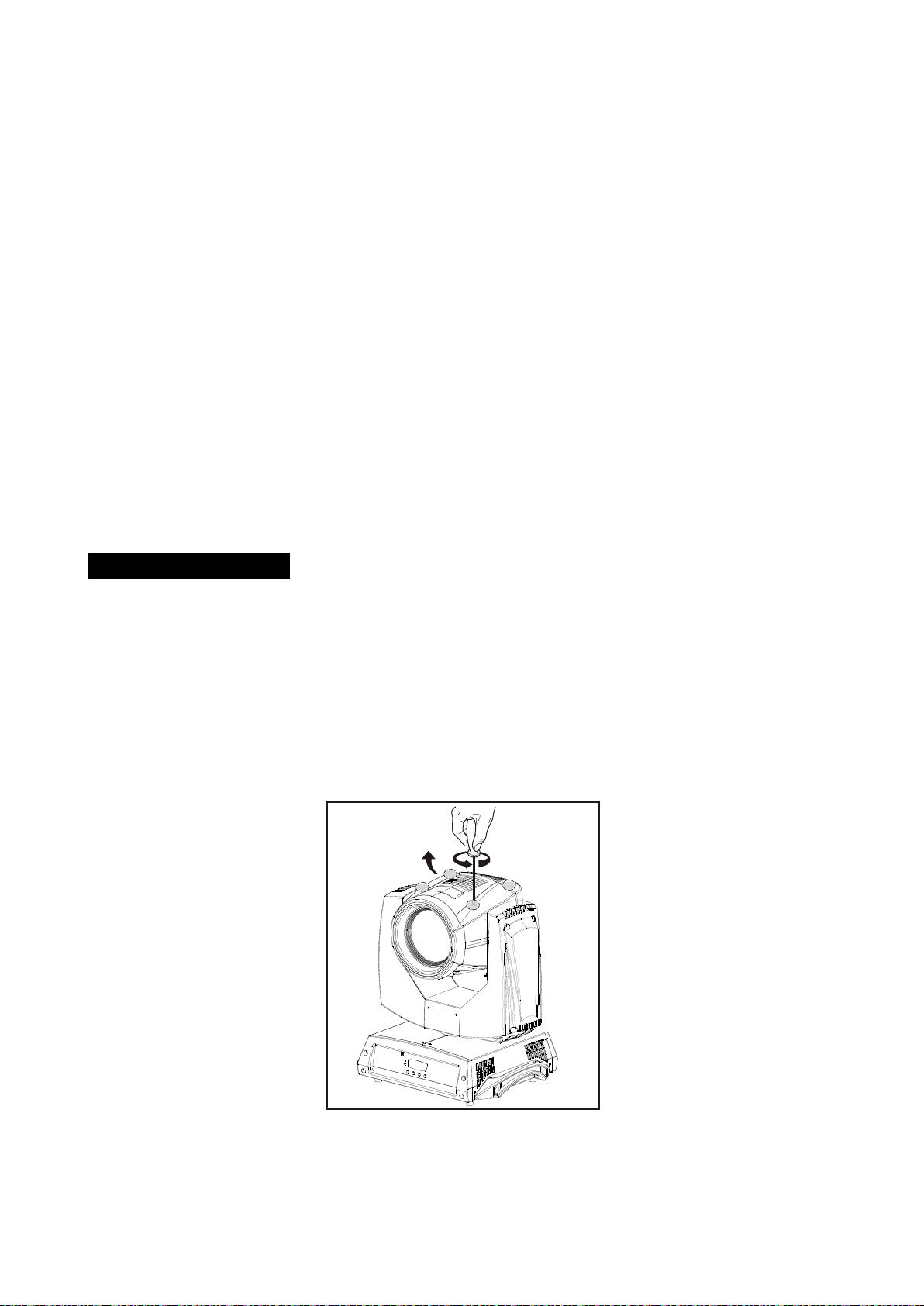
Installation:
1. Bolt each clamp (1) to the Omega holder with screw and lock nut through the hole in the
holder.
2. Fasten the omega holders (2) on the bottom of the base by inserting quick-lock fasteners (3)
A 3B

into the holes of the base and tighten fully clockwise.
3. Hang the fixture to the support (4) through clamp and fasten the screws (5). Fasten the safety
cable (6) through the bottom of the base and over the support.
Attention:
Always ensure that the structure to which you are attaching the unit is secure and is able to
support a weight of 10 times of the unit’s weight without any harming deformation.
Also always use a safety cable that can hold 12 times of the weight of the unit when installing
the fixture.
Make absolute sure that the unit is firmly fixed in way that no vibrating or slipping would occur
during operation.
The equipment must be installed beyond the areas where persons may walk by or be seated.
The rigging has to be operated by or under the guide of a skilled person.
3. Technical Specification
Power Supply
:
100~240V,50/60Hz
Power Consumption
:
340W
Lamp
:
OSRAM SIRIUS HRI 231W
Beam Angle
:
1° / 3.8°
A 4B

Optical system
High efficient Optical system
Delivering extremely powerful output
High quality lens
Movement
Pan: 540°
Tilt: 270°
Pan/Tilt moving speed adjustable.
Automatic Pan/Tilt correction
Easy calibration and maintenance by Pan/Tilt magnetic home positioning
Dimmer/Shutter:
Mechanical dimmer
Mechanical shutter and adjustable speed strobe effect
Color wheel:
Color wheel: 14 fixed colors
Rainbow effect in both directions
Easy calibration and maintenance by magnetic home positioning
Gobo wheel:
Gobo Wheel: 17 fixed gobos, index able,
Easy calibration and maintenance by magnetic home positioning
Prism:
8-facet rotating prism Frost
Protocols:
DMX 512
Data input/output: 3 Pin XLR socket
Dimension
:
500×394×325mm
Weight
:
18kg
Focus
:
Electronic
A 5B

Cooling
:
Fan Cooling
4. Fixture Description
4.1 Control Panel
Front View
Rear View
1. Microphone
:
To receive music for sound active;
2. LED:
POWER
On
Power On
DMX
On
DMX input present
3. Button:
MENU
To select the programming functions
UP
To go forward in the selected functions
DOWN
To go backward in the selected functions
ENTER
To confirm the selected functions
4. Function Display: Used to show the various menus and the selected function;
Distance(m)
5 10 15 20
3.8 Lux°
800000 200000 99000 59000
Diameter(m) 0.4 0.7 1.21 1.5
3.8°
Photometrics Diagram
A 6B

5. DMX IN: DMX 512 link, use 3-pin XLR cable to link the unit and DMX controller;
6. DMX OUT: DMX 512 operation, use 3-pin XLR cable to link the next units;
7. FUSE (T 6.3A): Protect the unit from damage of over voltage or short circuit;
8. MAINS IN:
PowerCon connection from main power supply;
9. MAINS OUT:
PowerCon loop connection for main power supply to the next unit.
5. Gobo Wheel and Lamp
5.1 Gobo Wheel
DANGER!
Install/change the gobo-wheel with the device switched off only
5.2 Lamp
Philips MSD Platinum 5R (8000K)
Because of its high internal pressure, there might be a risk that the Discharge
lamp would explode during operation. The lamp emits intense UV radiation which is
harmful to the eyes and skin. The high luminance of the arc can cause severe damage to
A 7B

the retina if you take a close look at the lamp.
To protect the lamp, always turn off the lamp first (via control panel or DMX controller)
and let the unit run at least five minutes to cool down before switching off the mains
supply. Never handle the lamp or luminary when it is hot.
Do not touch the bulb with bare hands. If this happens, clean the lamp with denatured
alcohol and wipe it with a lint free cloth before installation.
The lamp generates UV radiation. Never operate the lamp without appropriate shielding.
When lighting up, the lamp operates at high pressure and there is a slight risk of arc tube
rupture. The risk increases with age, temperature and improper handling of the lamp. Do
not use the lamp longer than its lifespan.
Make sure the lamp is located in the center of the reflector for the best projection
5.3 Change The Lamp
Do not use this lamp more than 3000 hours, Using the lamp any longer than its set life could
seriously damage your unit. Periodically checking the lamp running time, when the lamp reaches
the 3000 hour mark, or close to it, we strongly suggest you switch the lamp out. Clear the RESET
TIME after you have replaced the lamp.
1. Remove the fixture head covers using a screwdriver (Figure 1).
Figure 1
A 8B

2. Position the head as Figure 2 and remove the lamp cooling fan at the rear of the head.
Figure 2
3. Lift the lamp out of its recess as Figure 3.
Figure 3
4. Disconnect the lamp and connect the replacement lamp (Figure 4).Place the new lamp into the
lamp recess.(Figure 5)
A 9B

Figure 4 Figure 5
5. See illustration below. Adjust the lamp using a slotted (flat head) screwdriver until it is
centralized.
Figure 6
6. Reinstall the fan and secure it, then replace and secure the head covers before reapplying
po we r.
6. How to set the fixture
6.1 Main Function
To select any of the given functions, press the MENU button up to when the required one is
showing on the display. Select the function by the ENTER button and the display will blink. Use the
DOWN and UP button to change the mode. Once the required mode has been selected, press the
ENTER button to setup, to go back to the functions without any change press the MENU button
again. Hold and press the MENU button about one second or wait for one minute to exit the menu
mode.
The main functions are showing below:
A 10B

A 11B

DMX 512 Address
Select the , press the ENTER button to confirm, the display will show the present address.
Use the UP and DOWN button to adjust the address from (1) to (512),press the
ENTER button to store. Press the MENU button back to the last menu or idling 30 seconds to exit
menu mode.
Channel Mode
Select the , press the ENTER button to confirm, the display will show the present channel
mode. Use the UP and DOWN button to adjust (16 channel), (15 channel),
(19 channel) or (20 channel),press the ENTER button to store. Press the MENU
button back to the last menu or idling 30 seconds to exit menu mode.
Pan Inverse
Select , press the ENTER button to confirm, use the UP and DOWN button to select the
(no) or (yes), press the ENTER button to store. Press the MENU button back to
the last menu or idling 30 seconds to exit menu mode.
Tilt Reverse
Select , press the ENTER button to confirm, use the UP and DOWN button to select the
(no) or (yes), press the ENTER button to store. Press the MENU button back to
the last menu or idling 30 seconds to exit menu mode.
Led Display
Select , press the ENTER button to confirm, use the UP and DOWN button to select the
(on) or (off), press the ENTER button to store. Press the MENU button back to
the last menu or idling 30 seconds to exit menu mode.
Display Inverse
Select , press the ENTER button to confirm, use the ENTER button to select . Press
A 12B

the MENU button back to the last menu or idling 30 seconds to exit menu mode.
Auto Test
Select , press the ENTER button to confirm, then the unit will test by itself. Press the
MENU button back to the last menu.
Fixture Use Hours
Press the MENU button up to when the is blinking on the display. Press the ENTER button
and the display will show the number of working hours of the unit. To go back to the functions press
the MENU button again.
Lamp On/Off
Select , press the ENTER button to confirm, use the UP and DOWN button to select the
(Off) or (On), press the ENTER button to store. Press the MENU button back to
the last menu or idling 30 seconds to exit menu mode.
Lamp On/Off While Power On
Select , press the ENTER button to confirm, use the UP and DOWN button to select the
(Lamp Off while power on) or (Lamp On while power on), press the ENTER
button to store. Press the MENU button back to the last menu or idling 30 seconds to exit menu
mode.
Firmware Version
Press the MENU button up to when the is blinking on the display. Press the ENTER button
and the display will show the version of software of the unit. To go back to the functions press the
MENU button again.
Default
Select , press the ENTER button to confirm, use the UP and DOWN button to select the
A 13B

(No) or (Yes), press the ENTER button to store. Press the MENU button back to
the last menu or idling 30 seconds to exit menu mode.
Reset
Press the MENU button up to when the is blinking on the display. Press the ENTER button
and the fixture will reset.
6.2 Home Position Adjustment
Press the MENU button into menu mode, then press and hold the ENTER button for about 3
seconds into offset mode to adjust the home position. Select the function by the ENTER button.
Use the UP/DOWN button to select the submenu, press the ENTER button to store and
automatically return to the last menu. Press the MENU button to exit.
A 14B

— Pan home position adjustment
To select the , press the ENTER button to show the PAN OFFSET on the display. Use the
DOWN and UP button to adjust the value from 0 to 255, press the ENTER button to store. Press
the MENU button to exit.
—Tilt home position adjustment
To select the , press the ENTER button to show the TILT OFFSET on the display. Use the
DOWN and UP button to adjust the value from -127 to 127, press the ENTER button to store.
Press the MENU button to exit.
—Dimmer home position adjustment
To select the , press the ENTER button to show the PAN OFFSET on the display. Use the
DOWN and UP button to adjust the value from 0 to 255, press the ENTER button to store. Press
the MENU button to exit.
—Color home position adjustment
To select the , press the ENTER button to show the Color OFFSET on the display. Use the
DOWN and UP button to adjust the value from -127 to 127, press the ENTER button to store. Press
the MENU button to exit.
—Gobo home position adjustment
To select the , press the ENTER button to show the Gobo OFFSET on the display. Use the
DOWN and UP button to adjust the value from -127 to 127, press the ENTER button to store. Press
the MENU button to exit.
—Prism home position adjustment
To select the , press the ENTER button to show the Prism OFFSETon the display. Use the
DOWN and UP button to adjust the value from 0 to 255, press the ENTER button to store. Press the
A 15B

MENU button to exit.
—R-Prism home position adjustment
To select the , press the ENTER button to show the R-Prism OFFSET on the display. Use the
DOWN and UP button to adjust the value from -127 to 127, press the ENTER button to store. Press
the MENU button to exit.
—Frost home position adjustment
To select the , press the ENTER button to show the Frost OFFSET on the display. Use the
DOWN and UP button to adjust the value from 0 to 255, press the ENTER button to store. Press the
MENU button to exit.
—Focus home position adjustment
To select the , press the ENTER button to show the Focus OFFSET on the display. Use the
DOWN and UP button to adjust the value from 0 to 255, press the ENTER button to store. Press the
MENU button to exit.
7. Control By Universal DMX Controller
7.1 DMX Connections
A 16B

1. At last unit, the DMX cable has to be terminated with a terminator. Solder a 120-ohm 1/4W
resistor between pin 2(DMX-) and pin 3(DMX+) into a 3-pin XLR-plug and plug it in the
DMX-output of the last unit.
2. Connect the unit together in a “daisy chain” by XLR plug cable from the output of the unit to
the input of the next unit. The cable cannot be branched or split to a “Y” cable. DMX 512 is a
very high-speed signal. Inadequate or damaged cables, soldered joints or corroded connectors
can easily distort the signal and shut down the system.
3. The DMX output and input connectors are pass-through to maintain the DMX circuit, when
one of the units’ power is disconnected.
4. Each lighting unit needs to have a DMX address to receive the data by the controller. The
address number is between 0-511 (usually 0 & 1 are equal to 1).
5. The end of the DMX 512 system should be terminated to reduce signal errors.
6. 3 pin XLR connectors are more popular than 5 pins XLR.
3 pin XLR: Pin 1: GND, Pin 2: Negative signal (-), Pin 3: Positive signal (+)
5 pin XLR: Pin 1: GND, Pin 2: Negative signal (-), Pin 3: Positive signal (+), Pin4, Pin5 not used.
7.2 Channel Mode Setting
Enter menu mode, select DMX Functions, press the ENTER button to confirm, use the UP/DOWN
button to select Mode, press the ENTER button to confirm, present channel mode will blink on the
display, use the UP/DOWN button to select 16 Channel
、
15 Channel
、
19 Channel or 20 Channel
Mode, and press the ENTER button to store. Press the MENU button back to the last menu or let
the unit idle one minute to exit menu mode.
A 17B

7.3 DMX Address Setting
By using a universal DMX controller to control the units, you have to set DMX address from 1 to
512 so that the units can receive DMX signal.
Press the MENU button up to when the DMX Address is showing on the display. Pressing ENTER
button and the display will blink. Use DOWN and UP button to change the DMX512 address. Once
the address has been selected, press and keep ENTER button pressed up to when the display stops
blinking or storing automatically 8 seconds later. To go back to the functions without any change
press the MENU button again. If you use please refer to the following diagram to address your
DMX512 channel for the first 4 units:
16 Channels:
15 Channels:
19 Channels:
20 Channels:
7.4 DMX Control
16 Channels (Mode 1):
Channel Value Function
1
000 - 255
Pan
0 ° 540°
2 000 - 255 Pan Fine
3 000 - 255
Tilt
0 ° 270°
4 000 - 255 Tilt Fine
5 000 - 255
Pan/Tilt Speed
:
Fast Slow
6
000 - 049
050 - 059
Special Function
Null
Pan/Tilt fast mode
A 18B

060 - 069
070 - 079
080 - 089
090 - 099
100 - 109
110 - 119
120 - 129
130 - 139
140 - 149
150 - 159
160 - 169
170 - 179
180 –199
200 –209
210 - 219
220 - 229
230 - 239
240 - 255
Pan/Tilt normal mode
Blackout while pan/tilt move enable
Blackout while pan/tilt move disable
Blackout while color change enable
Blackout while color change disable
Blackout while gobo change enable
Blackout while gobo change disable
Lamp on
Pan/tilt reset
Color reset
Gobo reset
Shutter/prism/r-prism/frost/focus reset
Null
Reset all
Blackout while pan/tilt/gobo/color change enable
Blackout while pan/tilt/gobo/color change disable
Lamp off
Null
7
000 - 007
008 - 015
016 - 023
024 - 031
032 - 039
040 - 047
048 - 055
056 - 063
064 - 071
072 - 079
080 - 087
088 - 095
096 - 103
104 - 111
112 - 119
120 - 127
128 - 135
136 - 143
144– 151
152 - 159
160 - 167
168 - 175
176 - 183
184 –191
192 –199
200 - 207
208 - 215
Pan/Tilt Macro:
Off
Macro 1
Macro 2
Macro 3
Macro 4
Macro 5
Macro 6
Macro 7
Macro 8
Macro 9
Macro 10
Macro 11
Macro 12
Macro 13
Macro 14
Macro 15
Macro 16
Macro 17
Macro 18
Macro 19
Macro 20
Macro 21
Macro 22
Macro 23
Macro 24
Macro 25
Macro 26
A 19B
Table of contents
Other ACME Dj Equipment manuals

ACME
ACME Dotline360 TB-1230 QW User manual

ACME
ACME LED?7TC User manual

ACME
ACME iColorLed 18TC User manual

ACME
ACME LED-MS50A User manual

ACME
ACME Theatre LED Colour Flood User manual

ACME
ACME LED-747-1W User manual

ACME
ACME E-10 WW DXX User manual

ACME
ACME GENESIS COLOR II User manual

ACME
ACME FURY LED RGB User manual

ACME
ACME Color Par 36 User manual

ACME
ACME Stage Blinder P4 User manual

ACME
ACME ASTRO LED-256D User manual

ACME
ACME Junior Series User manual

ACME
ACME XP-1200F User manual

ACME
ACME O2 Oxygen User manual

ACME
ACME Color Spot User manual

ACME
ACME ELLIPSOIDAL E-300 User manual

ACME
ACME LED-RC8 User manual

ACME
ACME CB-16FC User manual

ACME
ACME LP-TS200 CW User manual