5 Automatic_Automatic-Z-200626-Rev014-UM-e
3.3 Wiring
The si gle-phase slicer is fitted with a sta dard plug.
Plug the machi e i to the outlet, maki g sure that the system features a electrical overload switch. To
improve safety further, i sert a 0.5 Amp fuse i the power supply box. The three-phase slicer is fitted with a
sta dard 16 Amp plug. Plug the machi e i to the suitable outlet, maki g sure it features a overload switch
as above.
The blade should rotate a ticlockwise see from the blade guard side.
Should the directio of rotatio of the three-phase slicers be i correct, i vert two of the three wires i the plug.
Unless otherwise indicated the three-phase slicer is always connected at 400 Volts.
Before connecting the slicer with the local electricity grid make sure that electrical indications
of identification plate and local electricity are the same.
3.4 Operation
Use the slicer as it was desig ed to be used. Never push the product towards the blade by ha d. The product
carriage is tilted so as to e able the product to slide towards the blade u der its ow weight.
Keep hands well away from the blade and use the relevant handle to move the product
carriage safely back and forth.
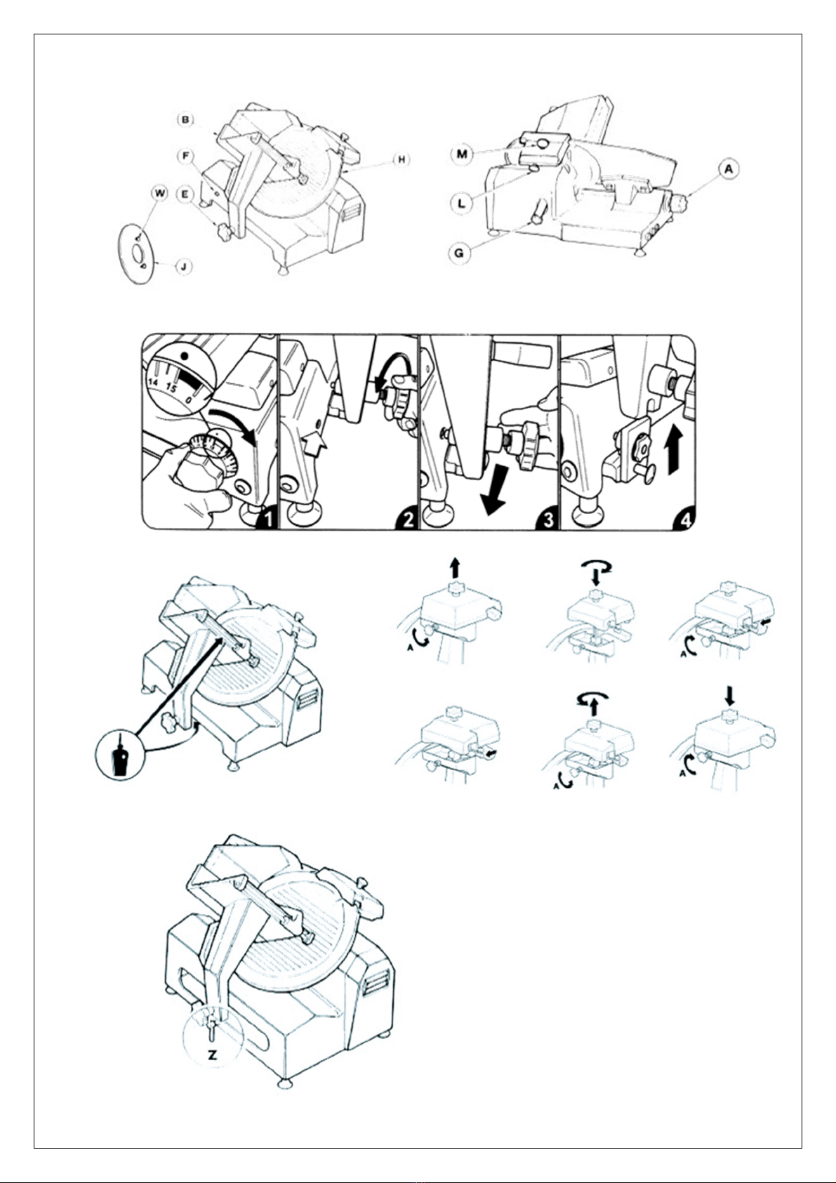
3.5 Operation in automatic mode
I the Automatic Gravity models with Gear Drive, the product carriage ca be operated i automatic mode.
Said mode ca be e abled or disabled by rotati g lever "Z" slightly, as i dicated i fig.5.
This operation must always be performed with the machine switched off.
5. CONTROLS AND SAFETY DEVICES
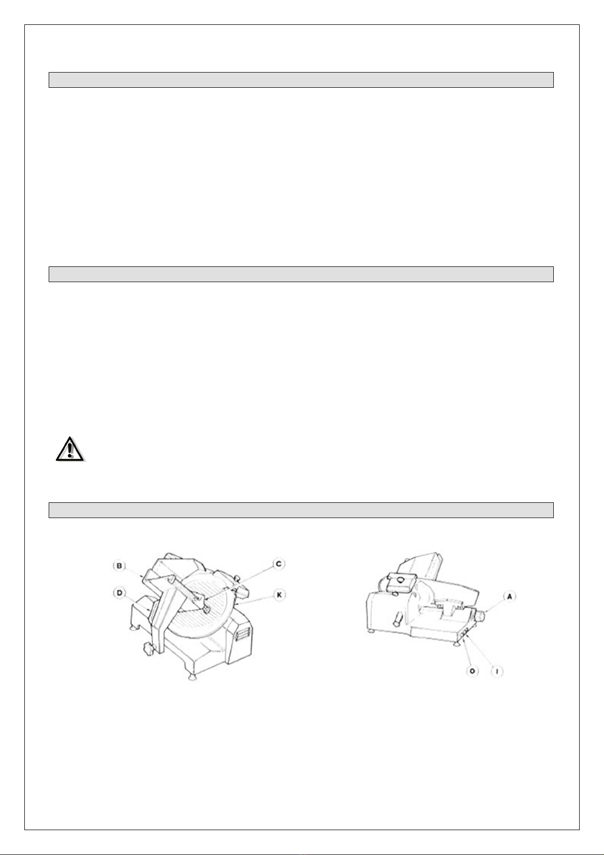
4.1 Controls
The Gear Drive Gravity slicers are switched o a d off electrically by mea s of two butto s, I (start) coloured
gree a d O (stop) coloured red. Both feature a white lamp which i dicates whe the blade is rotati g.
The machi e features a safety switch i the blade guard co ected with a o voltage relay.
Every time the supply voltage is cut off, the gree butto I (start) must be pressed to start the machi e up
agai .
4.2 Mechanical safety devices
- With the exceptio of the actual cutti g sectio , the blade is totally protected by a irremovable guard
which ca ’t be removed.
- The product carriage ca o ly be removed if the slice assembly covers the blade a d the graduated k ob
is set to "0" (zero).
- The slice assembly ca o ly be ope ed (usi g the graduated k ob) if the product carriage is secured i its
ormal operati g positio .
- The blade ca o ly be removed usi g the blade-removal tool supplied.
- No e of the safety devices ca be removed; disma tli g or tamperi g with them would make the machi e
u safe, a d result i the ma ufacturer o lo ger bei g respo sible for a y accide ts.
4.3 Testing
- Make sure all the slicer compo e ts are assembled properly.
- Check the ha dwheel securi g the blade guard is locked i place.
- Press the gree start butto a d the red stop butto to check the machi e ca be switched o a d off.
- Check the slidi g of the product carriage a d product press.
- Check th e sharpe i g device works properly.
- Check the ope i g of the slice assembly.
- Make sure the product carriage ca o ly be disassembled with the graduated k ob set to zero, a d that
said k ob remai s locked i place after disassembly.
If there are any hints for defects stop the machine immediately sign it with “DEFECT” and call
your service partner.