AFL FlexTester 3 User manual

www.AFLglobal.com or +1 (800) 321-5298, +1 (603) 528-7780
FLX380 FlexTester
3
Series
Quick Reference Guide
Advanced Test Equipment Rentals
www.atecorp.com 800-404-ATEC (2832)
®
E
s
t
a
b
l
i
s
h
e
d
1
9
8
1
2
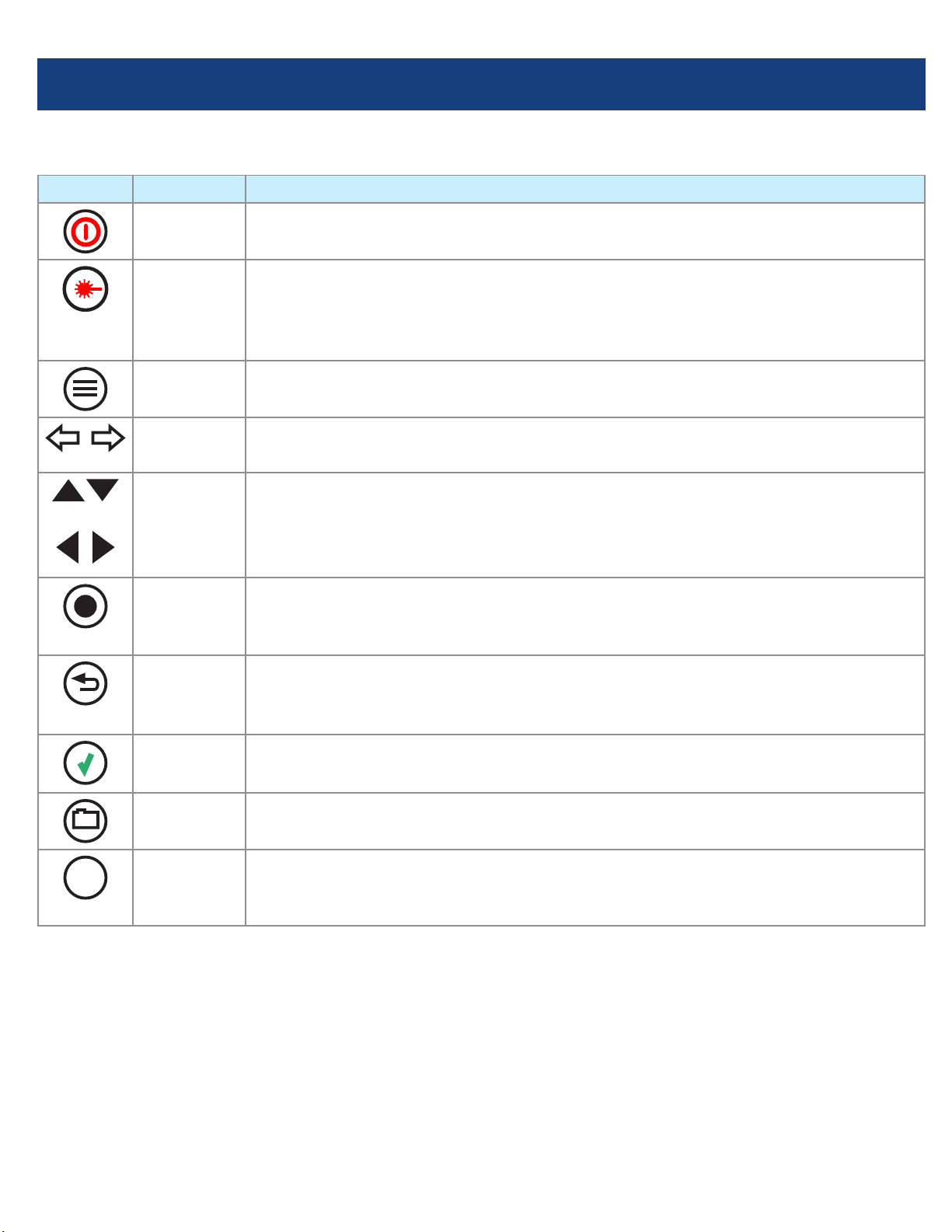
Functional Keys
KEY NAME KEY FUNCTION
Power Press and hold (~1 second) to turn the FLX380 on or off.
VFL Visual Fault Locator (red laser):
ON - Press and hold (~1 second) LED will ash.
ON - Press and hold (~2 seconds) LED will be solid.
OFF - Press and hold (~1 second) LED should be OFF.
Menu Press to access the Main Menu.
Left & Right
Tab keys
Press to display the next/previous available Menu Tab or Test View Tab.
Arrow
(Navigation)
keys
The arrow keys provide several functions:
•Main Menu: these keys are used to navigate menus and change setup parameters.
•Trace Page: in the Zoom mode, these keys are used to adjust zoom. In the Move
mode, Left and Right keys are used to move cursors.
Select (A/B) This key provides several functions:
•Main Menu: press to display a submenu (if available).
•Trace Page: press to toggle the active cursor between A and B.
Back Press once to return to the previous page.
Press one or more times, depending on which menu or editor submenu is displayed,
to return to the Main Menu.
Test Press to start or stop a test.
Save Provides several functions: save the currently displayed test results; set current
folder; set current le name; review results.
F1 Soft keys
(under
display)
The label shown in the display above each soft key (F1, F2 or F3) indicates the
current function for that key.
Press to select the indicated function.
Functional Keys

3
FLX380 FlexTester
3
Test Modes
OTDR Modes
TEST MODE NETWORK BEING TESTED APPLICATIONS SETUP
FTTx PON OTDR–
Test Customer
Fiber Only (to
splitter)
PON power meter.
Customer ber fault location (ber may be
live or dark).
Auto
FTTx PON OTDR–
Test Through
Splitter
End-to-end length, loss, and ORL.
Splitter loss.
Feeder ber fault location.
Semi-Auto
Full Auto (point-
to-point) Long-haul
Metro
Access
Fault location.
End-to-end length, loss, and ORL.
Connector loss and reection.
Splice loss.
Auto
Real Time Any Short range fault location.
First connector check.
Fusion splice check.
Mechanical splice tuning.
Semi-Auto
Expert Any Advanced point-to-point and FTTx PON.
testing for experienced OTDR users.
Manual or
Semi-auto
PON
OLT
PON
Light Source and Power Meter Mode
TEST MODE APPLICATION
Light Source •Measure end-to-end loss using manually set or Wave ID wavelength.
•Trace bers using tone generation and a NOYES Optical Fiber Identier (OFI).
Power Meter •Measure optical power or ber loss using manually set or automatically detected
(Wave ID) wavelength.

4
Running OTDR Tests and Viewing Results
Note: After an OTDR test is started, it may take several seconds for the rst results to appear and
depending on setup, tens of seconds or even several minutes for tests to complete.
FLX380 FlexTester
3
Main Menu Display Features
Main Menu Page (FLX380-303/-304 model shown)
Notes:
•FTTx PON OTDR combines functions of previous FTTx – In Service and FTTx – PON Construction modes.
•FTTx PON Power Meter measures downstream PON power levels in live PONs.
•Full Auto OTDR should only be used for point-to-point testing applications.
To Start a Test, press
Test key.
To Stop a Test
• Press
Test key. If pressed before trace appears, it will stop the test and display the setup menu. If pressed
after trace appears, it will stop the test, generate the event table and show the partially completed trace.
• Pressthe
Back key. OTDR stops the test and displays the setup menu.
Battery charge status icon.
- 100%
- <100%
- < 10%
Time-of-Day.
Page header.
Highlighted tab indicates
the currently displayed
Menu Page.
The currently highlighted
Menu option.
Press [Files] to open saved
les.
Main Menu tabs.
Press [USB] to transfer
saved results and download
software upgrades.
Press to display the last
OTDR trace viewed.

5
Launch Quality Check
A
C
D E F
B
The FlexTester3 OTDR features an optional launch quality check when an OTDR test is initiated.
To perform the launch quality check:
1. From the Main menu, display the Settings screen A
using keys.
2. Using keys navigate up/down the list to highlight the
Launch Quality Check parameter B.
3. If set to [Disabled], use keys to enable - display
[Enabled].
4. With the lunch quality check option enabled, press the Test
key to start an OTDR test.
5. The FLS380-30 will assess the loss and reectance at the
OTDR’s connection to the launch ring or ber-under-test.
6. If excess loss or reectance is detected, the OTDR reports
results and displays the ‘Poor Launch Quality’ screen C.
7. From the ‘Poor Launch Quality’ screen Cthe user may
chose to perform one of the following:
8. Cancel a test by pressing Cancel Dsoft key or
Back key .
9. Clean connectors and repeat the launch quality check by
pressing Re-check soft key Eor Enter key .
10. Continue testing without checking and cleaning the
connection by pressing Test soft key For Test key.

6
Test Settings: General OTDR Test Modes
Setup
Parameter
General-Purpose OTDR Test Mode
Full Auto Real Time Expert
Wavelength User selects single or multiple wavelength(s) at which to test.
Auto Setup N/A
(not applicable)
[Off]: User sets all parameters manually.
[By Range]: User sets [Range] & [Resolution], [Pulse width] &
[Averaging] selected automatically.
Range N/A: automatic User sets OTDR scan range.
Pulse width N/A: automatic,
based on auto-
detected range
Automatic if [Auto Setup] parameter is set to [By Range] option.
User-set if [Auto Setup] parameter is set to option [Off].
Averaging N/A: 1 second
updates
Automatic if [Auto Setup] is set to [By Range].
User-set if [Auto Setup] is set to [Off].
Resolution N/A: automatic User-set [High] or [Normal].
Range: When setting manually, select [Range],
which is at least 20% longer than the ber under
test.
Pulse width [Pulse]: Select wider pulse widths to
obtain cleaner traces (less noisy). Select narrower
pulse widths to detect events which are close
together (better resolution).
Averaging Time [Averaging]: Longer averaging
times produce cleaner traces.
Resolution: [High] resolution provides close data
spacing for more precise event location and better
detection of closely spaced events. [Normal]
resolution uses more ltering to provide a cleaner
trace, but with lower resolution.
7
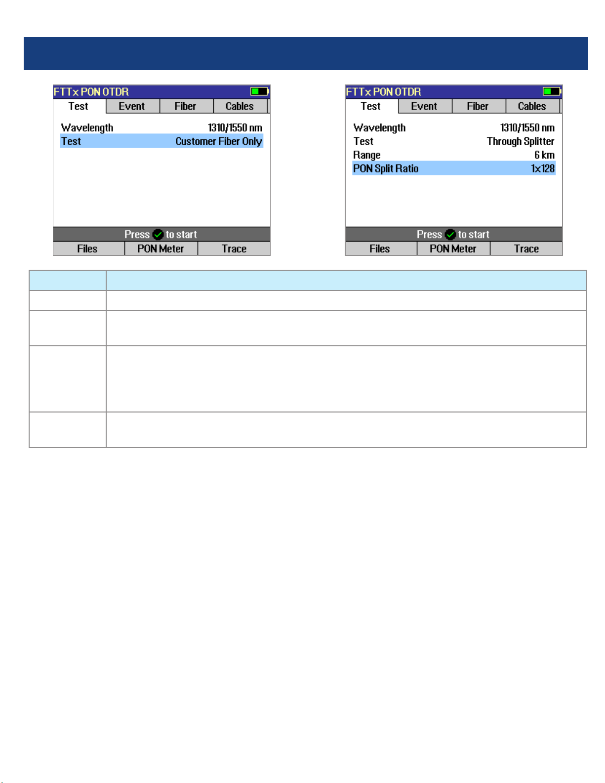
Parameter FTTx PON OTDR Test Mode
Wavelength User selects single or multiple wavelength(s) at which to test.
Range Auto: Range, pulse width, resolution, averaging are automatically determined.
Distance settings: User manually selects setting in range 250 m to 240 km.
Test If set to [Customer Fiber Only], tests only to the splitter using automatically determined
Range setting.
If set to [Through Splitter], tests through splitter including customer and feeder bers using
selected automatic or manual range setting.
PON Not present if [Test] parameter is set to [Customer Fiber Only] option. If [Test] is set to
[Through Splitter], user sets PON split ratio (1x8, 1x16, x132, 1x64, or 1x128).
Test Settings: FTTx PON OTDR Test Mode
Range: When setting manually, select [Range],
which is at least 20% longer than the ber under
test.
Pulse width [Pulse]: If testing through splitter,
pulse width is set automatically based on [Range]
and [PON] split ratio. If testing customer drop ber
only (In Service), automatically set based on range
to splitter.
When testing through a splitter, user can force
a wider pulse width to improve trace quality by
selecting a longer [Range] or higher [PON] split
ratio.
Averaging Time: Also set automatically.
Resolution: Since PONs are usually short, resolution
is typically set to High (close data spacing) for more
precise event location.

8
OTDR Mode: Trace Page Features
Soft key labels
(see next page for details)
Event Table displays OTDR
event measurements.
Information Page
displays OTDR setup
parameters, launch and
receive cable data, and
event thresholds.
Summary Page displays
end-to-end link
measurements.
A and B cursors.
Trace graph
(RED is current).
Receive cable
(if present).
File name (cable name + ber number), or “New
Trace” if le has not been saved.
Test Wavelengths (RED
is current).
Grid units display
dB/div on vertical axis
and distance/div on
horizontal axis.
Trace Page displays OTDR trace, A/B cursors,
Loss, Distance, and max reectance between A
and B cursors.
Launch cable
(if present).
Fiber under test.

9
OTDR Mode: Trace Page Features
Navigation Keys
Zoom mode Move mode
Note: Zoom expands/shrinks the trace around the
currently active cursor.
2-point Loss between A
and B cursor.
B cursor location (active
cursor is highlighted).
Distance between A
and B cursor.
For multi-wavelength
tests, press to toggle
active trace.
A cursor location.
Maximum Reectance
between A and B cursor.
Press to toggle Zoom and Move mode. In
Move mode, the key label will be displayed
as [ Zoom]. In Zoom mode, the key label
will be displayed as [ xZoom].
Press to Unzoom or
Rezoom.
Left
Move active
cursor
Right
Move active
cursor
A/B cursor
select
Vertical Zoom ( )
Vertical Zoom ( )
Horizontal
Zoom ( )
Horizontal
Zoom ( )
A/B cursor
select

10
OTDR Mode: Event Table Page Features
Event Table is automatically generated when the [Events] are set to [Auto] in the OTDR Event settings display.
Event Table displays:
[Number] of each event, event [Location] in
user selected units, event [Type], [Reectance]
and [Loss] in (dB) and loss/distance (dB/km).
Trace Graph.
For multiple-wavelength tests, press to toggle
the wavelength and display event table for
that wavelength.
Event Types
ICON EVENT TYPE DESCRIPTION
Start The start of the ber under test.
End The end of the ber under test.
Non-
reective
Loss Event
An event with measurable loss but very small or unmeasurable reectance, typically
caused by a fusion splice, ber break, or macrobend (with macrobend detection
disabled).
Non-
reective
Gainer Event
An event with ‘negative loss,’ which can occur in OTDR traces where two bers with
very different backscatter coefcients are spliced or connected. A gainer will be seen
as a normal (positive loss) event when tested from the other end of the ber. The true
loss of the event is approximately equal to the average of its loss measured from each
end of the ber under test.
Reective
Event
An event with measurable loss and reectance, typically caused by a connection or
mechanical splice.

11
OTDR Mode: Summary Page Features
For multiple-wavelength tests, press to toggle
the wavelength and display [Length], [Loss]
and [ORL] test results for that wavelength.
Summary page displays:
trace graph, ber under test [Length] in user
selected units, [Loss] and [ORL] in (dB).
ICON EVENT TYPE DESCRIPTION
Macrobend A non-reective loss event with signicantly higher loss at longer wavelengths (1550,
1625, 1650 nm) than seen at shorter wavelengths (1310, 1490 nm). Typically caused
by a sharp bend in the ber.
Splitter PON splitters are detected only when Event thresholds are set to PON Default or PON
User and a high loss event (> 6 dB) is detected which is determined not to be the end
of the ber.
Group Start
Event
First event in multiple event group. Reports loss of entire group. Reports
reectance of rst event in group if reectance of next event can be independently
measured. Reports max reectance of grouped events if next reectance cannot be
independently measured.
Group
Middle Event
Grouped events may contain zero, one, or more middle events. Loss of middle events
is included in group loss reported in the group start event. Reports reectance if it
can be independently measured.
Group End
Event
Last event in a multiple event group. Loss of last event is included in group loss
reported in group start event. Reports reectance if it can be independently
measured.
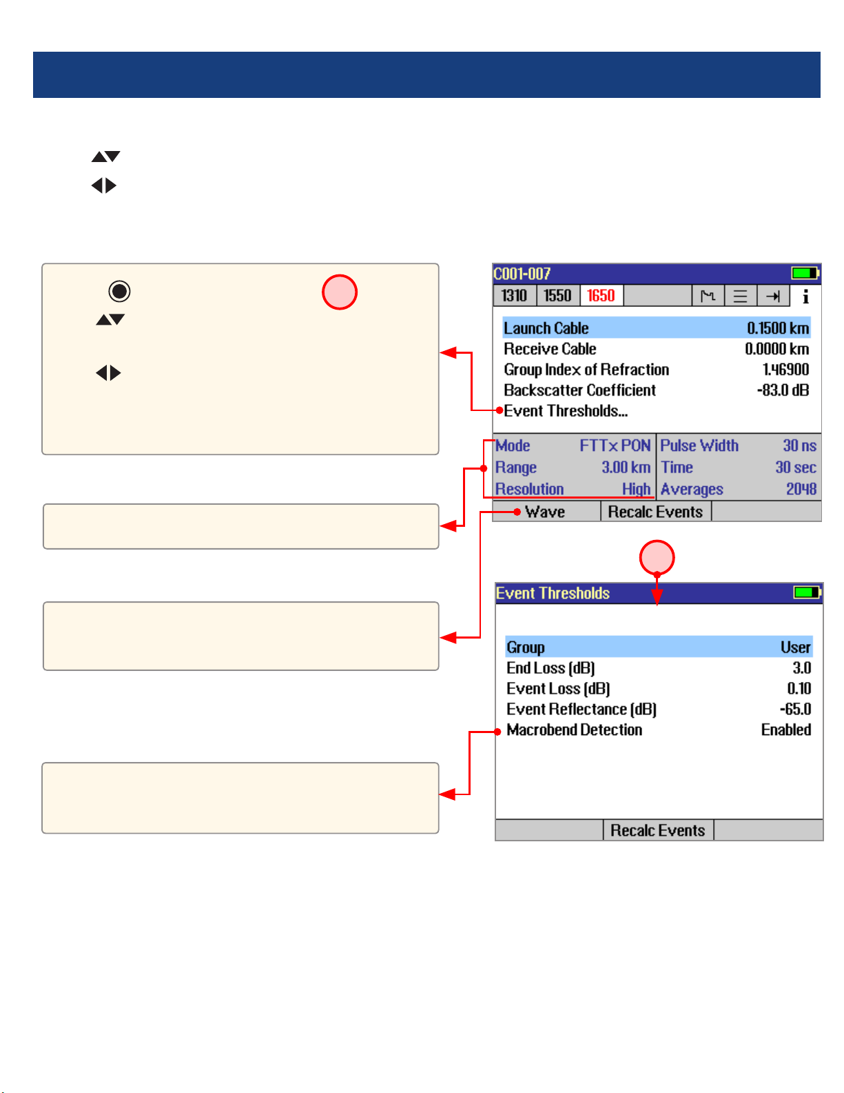
OTDR Mode: Event Table Page Features
12
The information page displays how the test was created.
• Use keys to highlight the desired setup parameter.
• Use keys to change the highlighted setup parameter (except [Event Thresholds…] parameter). You may
change these parameters to correct locations in the Event Table after the test is complete.
• When done, press [Recalc Events] to recalculate the Event Table.
For multiple-wavelength tests, press to toggle
the wavelength and display setup conditions for
that wavelength.
• Press key to display submenu A.
• Use keys to highlight the desired
parameter.
• Use keys to change the highlighted
parameter.
• When done, press [Recalc Events] to recalculate
the Event Table.
These elds show the current setup conditions.
OTDR Mode: Information Page Features
Event thresholds can be adjusted and
macrobend detection enabled or disabled before
recalculating events.
A
13
Saving Test Results
File Manager System
The FLX380 File Manager system consists of four pages:
PAGE NAME DESCRIPTION AND FUNCTION
Jobs Lists the Jobs (folders) stored in the FLX380 internal memory.
Use to open or delete the highlighted job folder.
Cables Lists the Cables (folders) in the currently open Job folder.
Use to open or delete the highlighted cable folder.
Results Lists the OTDR trace (.SOR) les and OPM results (.ATD) les in the currently open Cable
folder. Use to open (view) or delete the highlighted results le.
Save As Lists the current job, the current cable, and the ber number that will be used the next time a
group of traces is saved. Use to save the ‘new’ results created by the most recent test, or the
results most recently opened (recalled from memory).
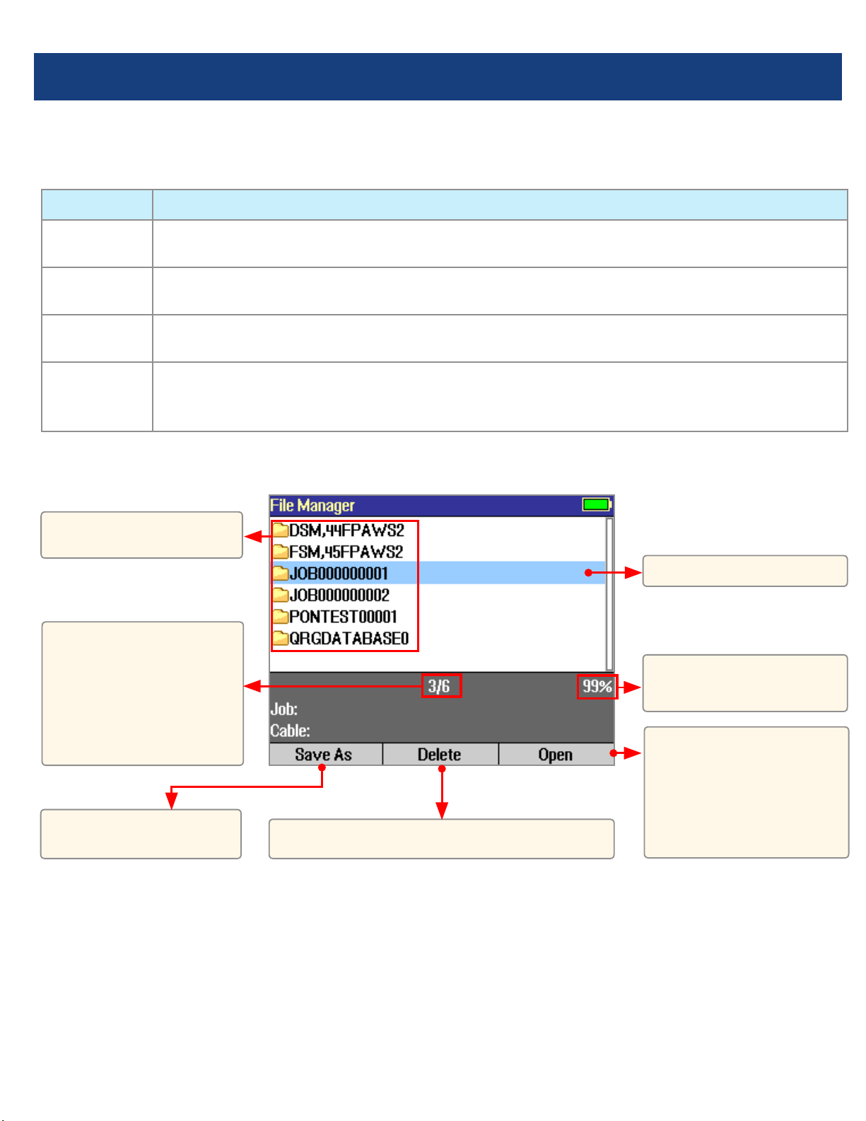
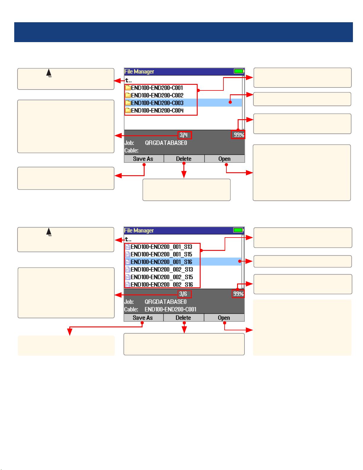
File Manager - Jobs Page
Press to open the
highlighted Job (which
becomes the current
job) and see a list of the
cables stored in this job.
Highlighted Job folder.
Free space
(internal memory).
Press to display the
Save As page.
List of saved Jobs
(folders).
This eld shows X/Y:
X = number of the
highlighted job
Y = total number of
jobs in FLX380 memory.
Press to delete the highlighted Job folder.
14
Saving Test Results
File Manager - Cables Page
File Manager - Results Page
Press to open the
highlighted cable (which
becomes the current cable)
and see a list of trace (.SOR)
and OPM (.ATD) les stored
for this cable.
List of saved Cables
(folders).
List of saved results (OTDR
.SOR and OPM .ATD les).
Highlighted Cable folder.
Highlighted trace.
Free space (internal
memory).
Free space
(internal memory).
Press to open the
highlighted trace or OPM
result. Opening the selected
trace le will open traces for
all wavelengths having the
same ber number.
Select ( ..) to return to
Jobs page.
Select ( ..) to return to
Cables page.
Press to display the Save
As page.
Press to display the Save
As page.
This eld shows X/Y:
X = number of the
highlighted cable
Y = total number of cables
in the current job.
This eld shows X/Y:
X = number of the
highlighted results le
Y = total number of results
les in the current cable.
Press to delete the
highlighted Cable folder
Press to delete the highlighted
trace or OPM results le.
15
Saving Test Results
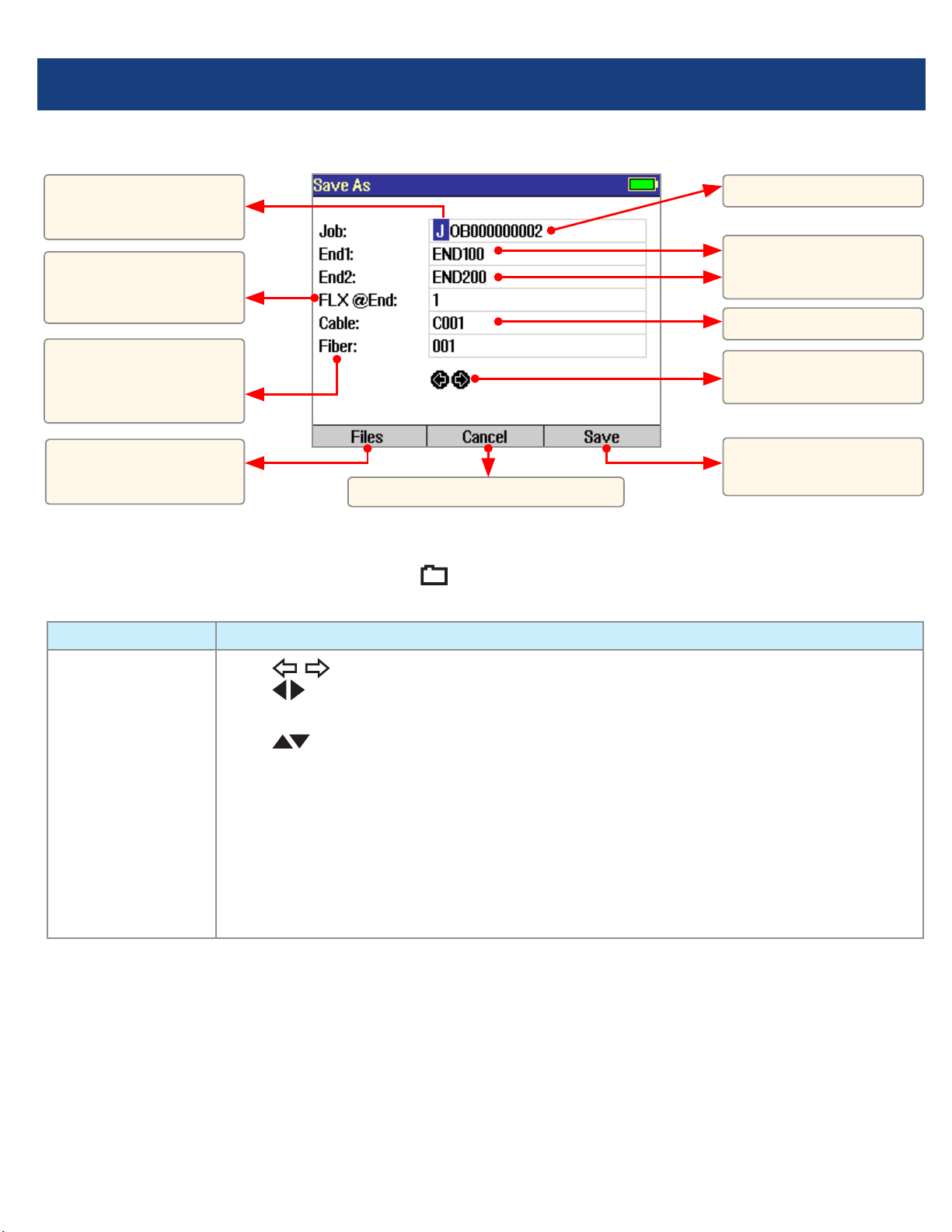
File Manager - Save As Page
Saving Results
1 Once a test is complete, press the Save key to display the [Save As] page.
2 Perform the following steps to save to an existing Job/Cable folder or save to a new folder:
EXISTING FOLDER NEW FOLDER
•Press the [Save]
soft key to save
test results with
the currently
displayed Job,
Route, Cable and
Fiber number.
•Use keys to select the previous / next eld to edit.
•Use keys to highlight any character position within the Job/End1/End2/Cable
name elds and Fiber number eld.
•Use keys to change the highlighted character.
- If the Job/End1/End2/Cable name and Fiber number are edited to a name and
number that already exists in the current folder, then pressing the [Save] key will
cause the FLX380 to display “Overwrite le?”.
- If the Job/End1/End2/Cable name is edited to a new name, then pressing the
[Save] key will cause the FLX380 to create a new folder of this name.
Note: This is the only way to create new folders!
•When done, press the [Save] soft key.
Press to save test
results.
Job name.
FLX380 location:
End 1 or End 2.
Route (made up of the
two end names).
Cable name.
Previous and Next
eld.
Fiber number auto-
increments or set by
user.
Currently highlighted
character.
Press to return to Main Menu.
Press to view current
Job/Cable page.

16
Light Source and Power Meter Test Mode
Wave ID Mode Feature
The Wave ID (automatic wavelength identication) feature signicantly increases efciency:
• Cutstesttimeinhalf(ormore)bytestingmultiplewavelengthssimultaneously.
• Eliminatesusersetuperrorandtheneedtocoordinatemanualsettingofwavelengthsbyuserslocatedat
opposite ends of the ber under test.
The “Wave ID” eld Ato the left of the displayed Power Meter wavelength will display one of the following:
• 270Hz,330Hz,1kHz,2kHz,orWaveID.Ifnoneofthesearedetected,thisOPMeldisblank.
• WhenWaveIDisdisplayed,Powerorlossismeasuredanddisplayedfortheautomaticallydetectedwavelengths.
• Inothermodes,thewavelengthmustbemanuallysetbuttonefrequencyisautomaticallydetected.
Press to toggle units:
• dBtomeasureloss,
• dBmorWtomeasurepower
Press to toggle
OPM wavelength.
Hold to set OPM reference level. Press briey to see current reference levels.
Turn laser On/Off.
Select wavelength(s).
Select test mode: CW, 270
Hz,330 Hz, 1 kHz and 2 kHz
tones, or Wave ID.
Use keys to navigate Light Source menu.
Use keys to change Light Source menu items.
Light Source
settings
Power Meter
settings
source
source
source
meter
meter
meter
A

17
Transferring Files to a PC using USB
To transfer les from your FLX380 to a PC using a USB cable, perform the following:
1 Connect your FLX380 to a PC using the supplied type A to Mini USB cable. Make sure the mini-plug is fully
seated in your FLX380.
2 Press the [USB] soft key on the FLX380’s Main Menu.
3 From your PC desktop, open My Computer. A new removable drive named [OFL X:] will appear, where ‘X:’ is
the drive letter assigned to your FLX380 by the PC.
4 Under [OFL X:] you should see two folders: [RESULTS] and [SOFTWARE]. Copy the [RESULTS] folder to your PC.
5 Under [RESULTS] you will see: [TRACES]. Under [TRACES] you will see all of the folders containing OTDR traces
or OPM results.
Note: Before removing the USB cable connecting your FLX380 to your PC, or pressing the [Cancel] soft key on
the USB page, left click the Safely Remove Hardware icon in the Start bar of your PC, then left click the Safely
Remove USB mass storage device – Drive (X:) message, where ‘X’ is the drive letter assigned to your FLX380.
For detailed operating instructions, refer to the FLX380 User’s Guide (available on supplied CD and
www.AFLglobal.com).
FLX380-303 and -304 support AFL’s ServiceSafe™ capability (US patent 8,411,259), enabling both in-service and
out-of-service OTDR testing and live PON power measurements to be made from a single port. In the FTTx PON
Power Meter mode, the rst screen displays received FTTx PON power at 1490 and 1550 nm. An OTDR test can
be initiated from the PON Power
Meter mode. On dark bers, users
can test at 1310/1550 nm. On live
bers, users can test at only 1625
or 1650 nm.
FTTx PON Power Meter (FLX380-303 and FLX380-304 models only!)

Thank you for choosing NOYES Test and Inspection!
C
E
R
T
I
F
I
E
D
9001
ISO
N
O
Y
E
S
F
I
B
E
R
S
Y
S
T
E
M
S
www.AFLglobal.com or +1 (800) 321-5298, +1 (603) 528-7780
© 2013 AFL , all rights reserved. FLX3-3X-1ENG Revision 1A, 2013-07-30
This manual suits for next models
3
Table of contents
Other AFL Test Equipment manuals


AFL
AFL M710 Series Installation instructions

AFL
AFL Noyes OPM4-3D User manual

AFL
AFL FOCIS Lightning 2 User manual

AFL
AFL FOCIS WiFi2 User manual

AFL
AFL Noyes OPM4 User manual

AFL
AFL ROGUE cB1 User manual

AFL
AFL VFI4 User manual

AFL
AFL MFIS User manual

AFL
AFL FOCIS Lightning 2 User manual

AFL
AFL ROGUE cB1 User manual


